

cdtechno NMV2412D, NMV2412DA, NMV2412SA, NMV2415D, NMV2415DA Datasheet
...
FEATURES
■ 3kVDC Isolation (1 minute)
■ Single or Dual Output
■ Industry Standard Pinout
■ Power Sharing on Dual Output
■ Efficiency to 80%
■ Power Density up to 0.90W/cm
3
■ 24V & 48V Input
■ 5V, 9V, 12V and 15V Output
■ Footprint from 1.17cm
2
■ UL 94V-0 Package Material
■ No Heatsink Required
■ Internal SMD Construction
■ Toroidal Magnetics
■ Fully Encapsulated
■ No External Components Required
■ Custom Solutions Available
■ No Electrolytic or Tantalum
Capacitors
DESCRIPTION
The NMV Series offers single or dual output
versions in the same size package as the
popular NMA series. The higher isolation is
particularly useful in control type applications
where the standard 1kV is not sufficient.
NMV 24V & 48V SERIES
3kVDC Isolated 1W Single & Dual Output DC-DC Converters
SELECTION GUIDE
Order Code (V) (V) (mA) % mV p-p (%) (pF) kHrs
NMV2405DA 24 5 200 15 150 70 33 201
NMV2409DA 24 9 111 10 150 80 40 185
NMV2412DA 24 12 84 10 150 80 55 163
NMV2415DA 24 15 67 10 150 80 70 136
NMV2405SA 24 5 200 15 150 70 33 201
NMV2409SA 24 9 111 10 150 80 40 185
NMV2412SA 24 12 84 10 150 80 55 163
NMV2415SA 24 15 67 10 150 80 70 136
NMV4805DA 48 5 200 15 150 70 48 213
NMV4809DA 48 9 111 10 150 70 59 194
NMV4812DA 48 12 84 10 150 70 70 169
NMV4815DA 48 15 67 10 150 70 81 140
NMV4805SA 48 5 200 15 150 70 48 213
NMV4809SA 48 9 111 10 150 70 59 194
NMV4812SA 48 12 84 10 150 70 70 169
NMV4815SA 48 15 67 10 150 70 81 140
NMV2405D 24 5 ±100 15 150 80 45 194
NMV2409D 24 9 ±55 10 150 70 52 166
NMV2412D 24 12 ±42 10 150 70 65 134
NMV2415D 24 15 ±33 10 150 70 70 101
NMV2405S 24 5 ±100 15 150 80 45 194
NMV2409S 24 9 ±55 10 150 70 52 166
NMV2412S 24 12 ±42 10 150 70 65 134
NMV2415S 24 15 ±33 10 150 70 70 101
NMV4805D 48 5 ±100 15 150 70 45 205
NMV4809D 48 9 ±55 10 150 70 58 175
NMV4812D 48 12 ±42 10 150 70 68 137
NMV4815D 48 15 ±33 10 150 70 75 102
NMV4805S 48 5 ±100 15 150 70 45 205
NMV4809S 48 9 ±55 10 150 70 58 175
NMV4812S 48 12 ±42 10 150 70 68 137
NMV4815S 48 15 ±33 10 150 70 75 102
When operated with additional external load capacitance the rise time of the input voltage will determine the
maximum external capacitance value for guaranteed start up. The slower the rise time of the input voltage the
greater the maximum value of the additional external capacitance for reliable start up.
INPUT CHARACTERISTICS
Parameter Conditions MIN TYP MAX Units
Voltage Range
Continuous operation, 24V input types 21.6 24 26.4
Continuous operation, 48V input types 43.2 48 52.8
DIP
SIP
DIP
SIP
DIP
SIP
DIP
SIP
V
www.dc-dc.com
OUTPUT CHARACTERISTICS
Parameter Conditions MIN TYP MAX Units
Rated Power2TA= 0°C to 70°C 1 W
Voltage Set
Point Accuracy
Line Regulation High VINto low V
See tolerance envelope
IN
1.2 %/%
ABSOLUTE MAXIMUM RATINGS
Short-circuit duration
Lead temperature 1.5mm from case for 10 seconds 300°C
Input voltage VIN, NMV24 types 28V
Input voltage VIN, NMV48 types 54V
1 Calculated using MIL-HDBK-217F with nominal input voltage at full load.
2 See derating curve
3 Supply voltage must be discontinued at the end of the short circuit duration.
All specifications typical at TA=25°C, nominal input voltage and rated output current unless otherwise specified.
3
1 second
NMV 24V & 48V SERIES
3kVDC Isolated 1W Single & Dual Output DC-DC Converters
ISOLATION CHARACTERISTICS
Parameter Conditions MIN TYP MAX Units
Isolation Test Voltage For 1 minute 3000 VDC
Resistance Viso=1000VDC 1 GΩ
GENERAL CHARACTERISTICS
Parameter Conditions MIN TYP MAX Units
Switching Frequency All input types 100 kHz
TEMPERATURE CHARACTERISTICS
Parameter Conditions MIN TYP MAX Units
Specification All output types 0 70 °C
Storage –55 150 °C
Cooling Free air convection
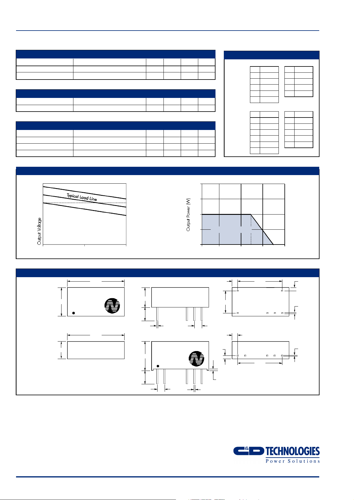
PERFORMANCE CHARACTERISTICS
+10%
+5%
V nominal
tolerance envelope
+2.5%
-2.5%
-7.5%
temperature derating graph
2.0
1.5
1.0
PIN CONNECTIONS
Single
Output
Variants
Dual
Output
Variants
14 Pin DIP
PIN
1 GND
7 NC
8 +V
10 0V
14 V
14 Pin DIP
PIN
1 GND
7 NC
8 +V
9 0V
10 –V
14 V
IN
IN
7 Pin SIP
PIN
1 V
2 GND
5 0V
7 +V
7 Pin SIP
PIN
1 V
2 GND
5 –V
6 0V
7 +V
IN
IN
10 50 100
Output Load Current (%)
MECHANICAL DIMENSIONS
14 Pin DIP
Weight: 2.11 g
19.50
NMV2405D
9.80
7 Pin SIP
Weight: 2.11 g
6.00
†
7.70 for 48V variants
††
7.50 for 48V variants
* Pin not fitted on single output variants
All dimensions in mm XX.XX ±0.25mm. All pins on a
2.54mm pitch and within ±0.25mm of true position.
XYYWW
19.50
††
4.60
3.60
4.60
3.60
†
6.80
NMV2415S
10.0
1 2 6* 75
0.55
0.45
XYYWW
2.54
0.5
Safe Operating Area
0
–50 0 50 70 100 125 150
Ambient Temperature (°C)
7.62
2.54
1.25
0.55
0.45
0.55
0.45
15.24 1.092.13
1.88±0.50
15.24
71
0.30
89*1014
0.20
0.30
0.20
C&D Technologies (NCL) Limited reserve the right to alter or improve the
specification, internal design or manufacturing process at any time, without
notice. Please check with your supplier or visit our web site to ensure that
you have the current and complete specification for your product before use.
© C&D Technologies (NCL) Limited 2001 NDC NMV2.3
No part of this publication may be copied, transmitted or stored in a
retrieval system or reproduced in any way including, but not limited to,
photography, photocopy, magnetic or other recording means, without prior
written permission from C&D Technologies (NCL) Limited.
Instructions for use are available from www.dc-dc.com
C&D Technologies (NCL) Ltd
Tanners Drive, Blakelands North
Milton Keynes MK14 5BU, England
Tel: +44 (0)1908 615232
Fax:+44 (0)1908 617545
email: info@cdtechno-ncl.com
www: http://www.dc-dc.com
C&D Technologies (NCL), Inc.
5816 Creedmoor Road, Raleigh
NC 27612, USA
Tel: +1 (919) 571-9405
Fax: +1 (919) 571-9262
email: info@us.cdtechno-ncl.com
 Loading...