

cdtechno NMT0572S, NMT1272S Datasheet
NMT SERIES
Triple Output 3W DC-DC Converters
FEATURES
■ Triple Outputs (–24V, –48V & –72V)
■ Toroidal Magnetics
■ Input/Output Isolation 1kVDC
■ Power Sharing on Outputs
■ Internal SMD Construction
■ Industrial Temperature Range
■ No External Components Required
■ Power Density 1.41W/cm
3
■ UL 94V-0 Package Material
DESCRIPTION
The NMT series is a range of DC-DC
converters offering three output voltages of
–24V, –48V and –72V from a single isolated
5V or 12V input voltage. The product is
designed for use with telecommunications
circuits requiring an on board supply for the
–72V RING-TIP connection service generated
from a nominal 5V or 12V DC input supply
rail. The device also offers battery level
voltages of –24V and –48V for access
control and data pump IC's. The product is
packaged in an 8 pin SIP case for minimum
PCB footprint. The rated power may be
shared or drawn from any one output
providing the total output load does not
exceed 3W.
www.dc-dc.com
SELECTION GUIDE
Nominal Rated Output Current2Output Current
Input Output
Voltage Output Voltage Load Load Load Load MTTF
MIN Full MIN Full
Order Code (V) V (mA) (mA) (mA) (mA) kHrs
VO1 –24 1.4 42 4.2 126
NMT0572S 5 VO2 –48 0.7 21 2.1 63 145
VO3 –72 0.5 14 1.4 42
VO1 –24 1.4 42 4.2 126
NMT1272S 12 VO2 –48 0.7 21 2.1 63 145
VO3 –72 0.5 14 1.4 42
When operated with additional external load capacitance the rise time of the input voltage will determine the
maximum external capacitance value for guaranteed start up. The slower the rise time of the input voltage the
greater the maximum value of the additional external capacitance for reliable start up.
3
INPUT CHARACTERISTICS
Parameter Conditions MIN TYP MAX Units
Voltage Range
(VIN)
Ripple Current
(I
)
RIPPLE
Zero Load Input
Current (I
NMT0572S 4.5 5.0 5.5
NMT1272S 10.8 12 13.2
NMT0572S 85
NMT1272S 66
NMT0572S, 0% output load 50 80
)
NMT1272S, 0% output load 27.5 50
CCZL
mA
mA
OUTPUT CHARACTERISTICS
Parameter Conditions MIN TYP MAX Units
Total Rated Power (P
OUT
)
Single Channel Voltage
Setpoint Accuracy
Output Voltage - VO1 (V
Output Voltage - VO2 (V
Output Voltage - VO3 (V
Line Regulation
Load Regulation P
Ripple & Noise
Total of all outputs or any
single output
P
= 100mW 0 10
OUT
P
= 3W –7.5 2.5
OUT
P
= 100mW 24.0 26.4
OUT
)
OUT
P
= 3W 22.2 24.6
OUT
P
= 100mW 48.0 52.8
OUT
)
OUT
P
= 3W 44.4 49.2
OUT
P
= 100mW 72.0 79.2
OUT
)
OUT
P
= 3W 66.6 73.8
OUT
VIN = 90% to 110%
of nominal
= 100mW to 3W 8 15 %
OUT
DC to 20MHz single
channel (24V)
0.1 3.0 W
1.01 1.2 %
0 220 400 mV
ABSOLUTE MAXIMUM RATINGS
Short-circuit duration
Lead temperature 1.5mm from case for 10 seconds 300°C
Input voltage VIN, NMT0572S 7V
Input voltage VIN, NMT1272S 15V
4
1 second
ISOLATION CHARACTERISTICS
Parameter Conditions MIN TYP MAX Units
Isolation Voltage (V
Isolation Capacitance (C
) Flash tested for 1 second 1000 VDC
ISOL
NMT0572S, 1MHz, 1V 65
)
ISOL
NMT1272S, 1MHz, 1V 130
Insulation Resistance 1000VDC test 1 10 GΩ
GENERAL CHARACTERISTICS
Parameter Conditions MIN TYP MAX Units
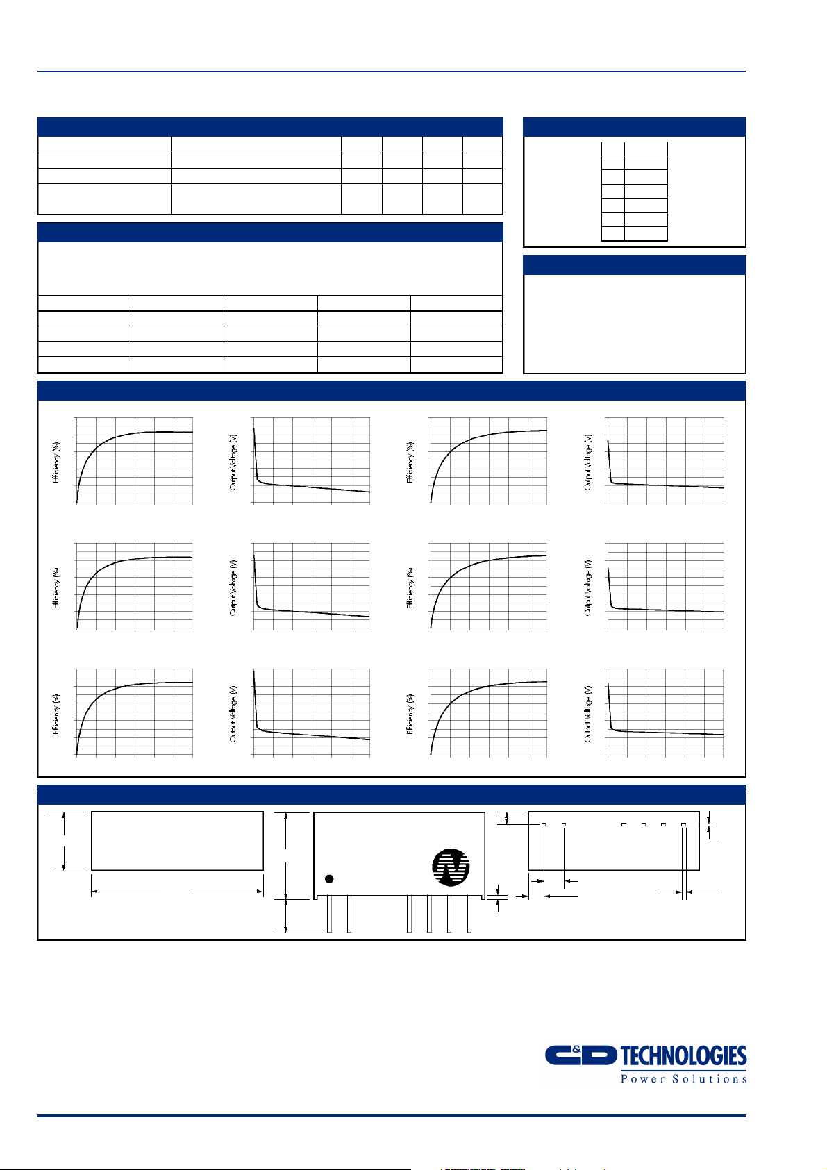
Efficiency All channels or any single channel 75 85 %
Switching Frequency (f
1 Calculated using MIL-HDBK-217F with nominal input voltage at full load.
2 Assuming all 3 channels are equally loaded.
3 Assuming only 1 channel is loaded.
4 Supply voltage must be discontinued at the end of the short circuit duration.
All specifications typical at TA=25°C, nominal input voltage and rated output current unless otherwise specified.
OSC
)
85 kHz
1
V
%
V
V
V
pF
NMT SERIES
Triple Output 3W DC-DC Converters
TEMPERATURE CHARACTERISTICS PIN CONNECTIONS
Parameter Conditions MIN TYP MAX Units
Operating Te m p e r a t u re (TA) -40 85 °C
Storage -50 125 °C
Case Temperature Rise
Above Ambient
1 litre static air chamber 27 °C
OUTPUT VOLTAGE CONFIGURATION
Although the output is described for negative rails, the input and output circuits are internally
isolated hence positive rails can also be generated, or a mixture of positive and negative.
The output 0V rail reference can be taken from any of the output terminals to give the range
of outputs as described in Output Voltage Configurations table below.
Channel Name Standard Ref Option 1 Option 2 Option 3
0 V 0 V + 2 4 V + 4 8 V + 7 2 V
V 0 1 – 2 4 V 0 V + 2 4 V + 4 8 V
V 0 2 – 4 8 V – 2 4 V 0 V + 2 4 V
V 0 3 – 7 2 V – 4 8 V – 2 4 V 0 V
PERFORMANCE CHARACTERISTICS
100
80
60
40
20
0
0 0.5 1.0 1.5 2.0 2.5 3.0
100
80
60
40
20
0
0 0.5 1.0 1.5 2.0 2.5 3.0
100
80
60
40
20
0
0 0.5 1.0 1.5 2.0 2.5 3.0
NMT0572S – Channel V01 (24V NOM) NMT1272S – Channel V01 (24V NOM)
Output Power (W)
NMT0572S – Channel V02 (48V NOM) NMT1272S – Channel V02 (48V NOM)
Output Power (W)
NMT0572S – Channel V03 (72V NOM) NMT1272S – Channel V03 (72V NOM)
Output Power (W)
40
36
32
28
24
20
0 0.5 1.0 1.5 2.0 2.5 3.0
Output Power (W)
80
72
64
56
48
40
0 0.5 1.0 1.5 2.0 2.5 3.0
Output Power (W)
120
108
96
84
72
60
0 0.5 1.0 1.5 2.0 2.5 3.0
Output Power (W)
100
80
60
40
20
0
0 0.5 1.0 1.5 2.0 2.5 3.0
Output Power (W)
100
80
60
40
20
0
0 0.5 1.0 1.5 2.0 2.5 3.0
Output Power (W)
100
80
60
40
20
0
0 0.5 1.0 1.5 2.0 2.5 3.0
Output Power (W)
POWER SHARING
The 3W total power delivery can be taken fro m
either a single channel, or from any combination of
all three channels. This allows an enormous amount
of flexibility, especially when combined with the
selectable output 0V re f e rence. For example, using
the option 2 output configuration; –24V at 0.5W,
+24V at 1W and +48V at 1.5W power supplies
a re available from a single NMT device.
PIN
1 V
2 GND
5 0V
6 V01
7 V02
8 V03
40
36
32
28
24
20
0 0.5 1.0 1.5 2.0 2.5 3.0
80
72
64
56
48
40
0 0.5 1.0 1.5 2.0 2.5 3.0
120
108
96
84
72
60
0 0.5 1.0 1.5 2.0 2.5 3.0
IN
Output Power (W)
Output Power (W)
Output Power (W)
MECHANICAL DIMENSIONS
7.50
11.10
21.80
4.60
Weight: 3.85g
C&D Technologies (NCL) Limited reserve the right to alter or improve the
specification, internal design or manufacturing process at any time, without
notice. Please check with your supplier or visit our web site to ensure that
you have the current and complete specification for your product before use.
© C&D Technologies (NCL) Limited 2001 NDC NMT.3
No part of this publication may be copied, transmitted or stored in a
retrieval system or reproduced in any way including, but not limited to,
photography, photocopy, magnetic or other recording means, without prior
written permission from C&D Technologies (NCL) Limited.
Instructions for use are available from www.dc-dc.com
3.60
NMT0572S
XYYWW
1 2 5 6 7 8
C&D Technologies (NCL) Ltd
Tanners Drive, Blakelands North
Milton Keynes MK14 5BU, England
Tel: +44 (0)1908 615232
Fax:+44 (0)1908 617545
email: info@cdtechno-ncl.com
www: http://www.dc-dc.com
1.17
0.55
0.45
2.54
2.10
All dimensions in mm XX.XX ±0.25mm.
All pins on a 2.54mm pitch and within ±0.25mm of true position.
C&D Technologies (NCL), Inc.
5816 Creedmoor Road, Raleigh
NC 27612, USA
Tel: +1 (919) 571-9405
Fax: +1 (919) 571-9262
email: info@us.cdtechno-ncl.com
0.30
0.20
0.55
0.45
 Loading...