

cdtechno NML0512S, NML1205S, NML1209S, NML1212S, NML1215S Datasheet
...
NML SERIES
Isolated 2W Single Output DC-DC Converters
SELECTION GUIDE
Nominal
Input Output Output Input Current
Voltage Voltage Current at Rated Load MTTF
Order Code (V) (V) (mA) (mA) (%) (pF) kHrs
NML0505S 5 5 400 513 78 19 2327
NML0509S 5 9 222 492 81 27 1393
NML0512S 5 12 167 479 84 32 832
1
FEATURES
■ Wide Temperature performance at
full 2 Watt load, –40°C to 85°C
■ Single Isolated Output
■ Pin Compatible with LME and
NME Series
■ Industry Standard Pinout
■ 1kVDC Isolation
■ Efficiency to 85%
■ Power Density up to 2.01W/cm
3
■ 5V & 12V Input
■ 5V, 9V, 12V and 15V Output
■ Footprint from 1.05cm
2
■ UL 94V-0 Package Material
■ No Heatsink Required
■ Internal SMD Construction
■ Toroidal Magnetics
■ Fully Encapsulated
■ No External Components Required
■ MTTF up to 2.9 Million hours
■ Custom Solutions Available
■ No Electrolytic or Tantalum
Capacitors
DESCRIPTION
The NML Series of DC-DC Converters is
particularly suited to isolating and/or
converting DC power rails. The galvanic
isolation allows the device to be configured
to provide an isolated negative rail in systems
where only positive rails exist. The wide
temperature range guarantees startup from
–40°C and full 2 watt output at 85°C. Pin
compatibility with the NME and LME ensures
ease of upgradeability.
NML0515S 5 15 133 481 83 27 481
NML1205S 12 5 400 207 81 28 716
NML1209S 12 9 222 198 84 42 593
NML1212S 12 12 167 197 85 46 461
NML1215S 12 15 133 197 85 54 328
When operated with additional external load capacitance the rise time of the input voltage will determine the
maximum external capacitance value for guaranteed start up. The slower the rise time of the input voltage the
greater the maximum value of the additional external capacitance for reliable start up.
INPUT CHARACTERISTICS
Parameter Conditions MIN TYP MAX Units
Voltage Range
Reflected
Ripple Current
Continuous operation, 5V input types 4.5 5 5.5
Continuous operation, 12V input types 10.8 12 13.2
5V input types
12V input types
20 33
23 38
V
mA p-p
OUTPUT CHARACTERISTICS
Parameter Conditions MIN TYP MAX Units
Rated Power2TA= –40°C to 85°C 2 W
Voltage Set
Point Accuracy
Line Regulation High VINto low V
Load Regulation
Ripple & Noise
See tolerance envelope
10% load to rated load, 5V output types 7.0 8.5
IN
10% load to rated load, 9V output types 4.5 5.2
10% load to rated load, 12V output types 4.5 5.5
10% load to rated load, 15V output types 3.7 8.5
NML0505S, BW=DC to 20MHz 96
NML0509S, BW=DC to 20MHz 67
NML0512S, BW=DC to 20MHz 59
NML0515S, BW=DC to 20MHz 53
NML1205S, BW=DC to 20MHz 76
NML1209S, BW=DC to 20MHz 63
NML1212S, BW=DC to 20MHz 53
NML1215S, BW=DC to 20MHz 45
1.0 1.2 %/%
200 mV p-p
%
ABSOLUTE MAXIMUM RATINGS
Internal power dissipation 805mW
Lead temperature 1.5mm from case for 10 seconds 300°C
Input voltage VIN, NML05 types 7V
Input voltage VIN, NML12 types 15V
www.dc-dc.com
1 Calculated using MIL-HDBK-217F with nominal input voltage at full load.
2 See derating curve
All specifications typical at TA=25°C, nominal input voltage and rated output current unless otherwise specified.
NML SERIES
Isolated 2W Single Output DC-DC Converters
ISOLATION CHARACTERISTICS
Parameter Conditions MIN TYP MAX Units
Isolation Test Voltage Flash tested for 1 second 1000 VDC
Resistance Viso=500VDC 10 GΩ
GENERAL CHARACTERISTICS
Parameter Conditions MIN TYP MAX Units
Switching Frequency
5V input types 90
12V input types 90
kHz
TEMPERATURE CHARACTERISTICS
Parameter Conditions MIN TYP MAX Units
Specification All output types –40 85 °C
Storage –50 130 °C
Case Temperature
Above Ambient
5V output types 45
All other output types 36
°C
Cooling Free air convection
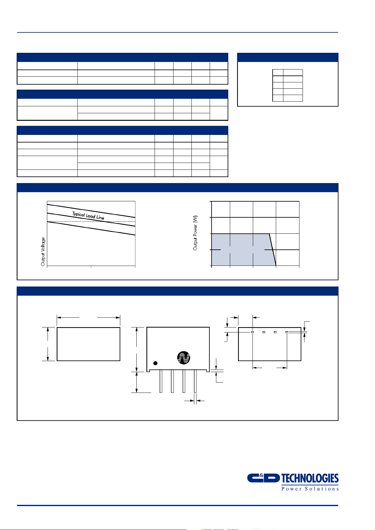
PERFORMANCE CHARACTERISTICS
+10%
+5%
V nominal
tolerance envelope
+2.5%
–2.5%
–7.5%
temperature derating graph
4.0
3.0
2.0
PIN CONNECTIONS
4 Pin SIP
PIN
1 GND
2 VIN
3 0V
4 +V
85°
10 50 100
Output Load Current (%)
MECHANICAL DIMENSIONS
4 Pin SIP
Weight: 2.0g
7.50
14.00
4.60
3.60
NML0505S
XYYWWi
10.0
1 2 3 4
1.0
Safe Operating Area
0
–40 0 50 100 150
0.55
0.45
Ambient Temperature (°C)
1.25
0.50
All dimensions in mm XX.XX ±0.25mm. All pins on a
2.54mm pitch and within ±0.25mm of true position.
3.38±0.50
7.62
0.30
0.20
C&D Technologies (NCL) Limited reserve the right to alter or improve the
specification, internal design or manufacturing process at any time, without
notice. Please check with your supplier or visit our web site to ensure that
you have the current and complete specification for your product before use.
© C&D Technologies (NCL) Limited 2001 NDC NML.3
No part of this publication may be copied, transmitted or stored in a
retrieval system or reproduced in any way including, but not limited to,
photography, photocopy, magnetic or other recording means, without prior
written permission from C&D Technologies (NCL) Limited.
Instructions for use are available from www.dc-dc.com
C&D Technologies (NCL) Ltd
Tanners Drive, Blakelands North
Milton Keynes MK14 5BU, England
Tel: +44 (0)1908 615232
Fax:+44 (0)1908 617545
email: info@cdtechno-ncl.com
www: http://www.dc-dc.com
C&D Technologies (NCL), Inc.
5816 Creedmoor Road, Raleigh
NC 27612, USA
Tel: +1 (919) 571-9405
Fax: +1 (919) 571-9262
email: info@us.cdtechno-ncl.com
 Loading...