

cdtechno NMH1215D, NMH1215S, NMH2405D, NMH1205D, NMH1209D Datasheet
...
FEATURES
■ Wide Temperature performance at
full 2 Watt load, –40°C to 85°C
■ Dual Output from a Single Input Rail
■ Industry Standard Pinout
■ Power Sharing on Output
■ 1kVDC Isolation
■ Efficiency to 86%
■ Power Density up to 1.44W/cm
3
■ 5V, 12V, 24V & 48V Input
■ 5V, 9V,12V and 15V Output
■ Footprint from 1.46cm
2
■ UL 94V-0 Package Material
■ No Heatsink Required
■ Internal SMD Construction
■ Toroidal Magnetics
■ Fully Encapsulated
■ No External Components Required
■ MTTF up to 2.0 Million hours
■ Custom Solutions Available
■ No Electrolytic or Tantalum
Capacitors
DESCRIPTION
The NMH series of industrial temperature
range DC-DC converters are the standard
building blocks for on-board point-of-use
power systems. They are ideally suited for
providing dual rail supplies on single rail
boards with the added benefit of galvanic
isolation to reduce circuit noise. All of the
rated power may be drawn from a single pin
provided the total load does not exceed 2W.
Pin compatibility with the NMA 1 watt series
ensures minimal effort in upgrading
distributed power systems.
www.dc-dc.com
NMH SERIES
Isolated 2W Dual Output DC-DC Converters
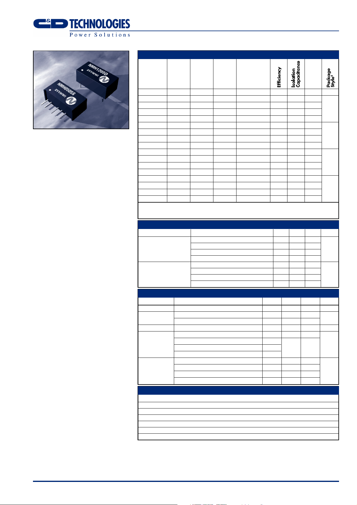
SELECTION GUIDE
Nominal
Input Output Output Input Current
Voltage Voltage Current at Rated Load MTTF
Order Code (V) (V) (mA) (mA) (%) (pF) kHrs
NMH0505S 5 5 ±200 500 80 24 1574
NMH0509S 5 9 ±111 494 81 28 663
NMH0512S 5 12 ±83 488 82 30 338
NMH0515S 5 15 ±67 476 84 33 187
NMH1205S 12 5 ±200 208 80 35 490
NMH1209S 12 9 ±111 201 83 55 343
NMH1212S 12 12 ±83 198 84 63 229
NMH1215S 12 15 ±67 198 84 66 148
NMH2405S 24 5 ±200 103 81 41 318
NMH2409S 24 9 ±111 98 85 75 249
NMH2412S 24 12 ±83 97 86 95 183
NMH2415S 24 15 ±67 97 86 104 127
NMH4805S 48 5 ±200 51 82 45 235
NMH4809S 48 9 ±111 51 82 74 195
NMH4812S 48 12 ±83 49 85 90 152
NMH4815S 48 15 ±67 49 85 112 112
When operated with additional external load capacitance the rise time of the input voltage will determine the
maximum external capacitance value for guaranteed start up. The slower the rise time of the input voltage the
greater the maximum value of the additional external capacitance for reliable start up.
INPUT CHARACTERISTICS
Parameter Conditions MIN TYP MAX Units
Continuous operation, 5V input types 4.5 5 5.5
Voltage Range
Continuous operation, 12V input types 10.8 12 13.2
Continuous operation, 24V input types 21.6 24 26.4
Continuous operation, 48V input types 43.2 48 52.8
5V input types 50
Reflected Ripple Current
12V input types 70
24V input types 130
48V input types 200
OUTPUT CHARACTERISTICS
Parameter Conditions MIN TYP MAX Units
Rated Power2TA= –40°C to 85°C 2 W
Output Voltage
Accuracy
Line Regulation High VINto low V
NMH0505 –5 7.5
All other types –5 5
IN
1.0 1.2 %/%
10% load to rated load, 5V output types 5 10
Load Regulation
10% load to rated load, 9V output types
10% load to rated load, 12V output types 3 10
10% load to rated load, 15V output types
BW=DC to 20MHz, 5V output types 150 200
Ripple & Noise
BW=DC to 20MHz, 9V output types 100 150
BW=DC to 20MHz, 12V output types 80 150
BW=DC to 20MHz, 15V output types 70 150
ABSOLUTE MAXIMUM RATINGS
Short circuit duration
Internal power dissipation 300mW
Lead temperature 1.5mm from case for 10 seconds 300°C
Input voltage VIN, NMH05 types 7V
Input voltage VIN, NMH12 types 15V
Input voltage VIN, NMH24 types 28V
Input voltage VIN, NMH48 types 54V
1 Calculated using MIL-HDBK-217F with nominal input voltage at full load.
2 See derating curve
3 Supply voltage must be discontinued at the end of the short circuit duration.
4 Replace suffix “S” with “D” for DIP package style.
All specifications typical at TA=25°C, nominal input voltage and rated output current unless otherwise specified.
3
1second
1
SIP
SIP
SIP
SIP
mA p-p
mV p-p
V
%
%
NMH SERIES
Isolated 2W Dual Output DC-DC Converters
ISOLATION CHARACTERISTICS
Parameter Conditions MIN TYP MAX Units
Isolation Test Voltage Flash tested for 1 second 1000 VDC
Resistance Viso=500V 1 10 GΩ
GENERAL CHARACTERISTICS
Parameter Conditions MIN TYP MAX Units
5V input types 95
Switching Frequency 12V input types 90 kHz
24 & 48V input types 80
TEMPERATURE CHARACTERISTICS
Parameter Conditions MIN TYP MAX Units
Specification All output types -40 85 °C
Storage -50 130 °C
Case Temperature
Above Ambient
5V output types 30
12V output types 25
°C
Cooling Free air convection
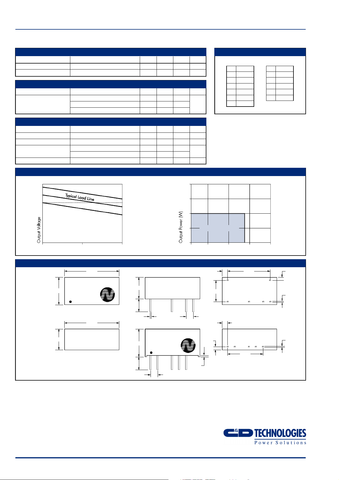
PERFORMANCE CHARACTERISTICS
+10%
+5%
V nominal
tolerance envelope
+2.5%
–2.5%
– 7.5%
temperature derating graph
4
3
2
PIN CONNECTIONS
14 Pin DIP
PIN
1 GND
7 NC
8 0V
9 +V
11 –V
IN
14 V
85°C
7 Pin SIP
PIN
1 VIN
2 GND
4 –V
5 0V
6 +V
10 50 100
Output Load Current (%)
MECHANICAL DIMENSIONS
14 Pin DIP
Weight: 2.85g
19.50
NMH0505D
9.80
7 Pin SIP
Weight: 2.76 g
7.50
C&D Technologies (NCL) Limited reserve the right to alter or improve the
specification, internal design or manufacturing process at any time, without
notice. Please check with your supplier or visit our web site to ensure that
you have the current and complete specification for your product before use.
© C&D Technologies (NCL) Limited 2001 NDC NMH.3
No part of this publication may be copied, transmitted or stored in a
retrieval system or reproduced in any way including, but not limited to,
photography, photocopy, magnetic or other recording means, without prior
written permission from C&D Technologies (NCL) Limited.
Instructions for use are available from www.dc-dc.com
XYYWWi
19.50
4.60
3.60
4.60
3.60
7.70
0.55
0.45
NMH0505S
10.0
XYYWWi
1 2 5 64
2.54
C&D Technologies (NCL) Ltd
Tanners Drive, Blakelands North
Milton Keynes MK14 5BU, England
Tel: +44 (0)1908 615232
Fax:+44 (0)1908 617545
email: info@cdtechno-ncl.com
www: http://www.dc-dc.com
Safe Operating Area
1
0
-40 0 50 100 150
Ambient Temperature (°C)
7.62
2.54
1.25
0.55
0.45
All dimensions in mm XX.XX ±0.25mm. All pins on a
2.54mm pitch and within ±0.25mm of true position.
C&D Technologies (NCL), Inc.
5816 Creedmoor Road, Raleigh
NC 27612, USA
Tel: +1 (919) 571-9405
Fax: +1 (919) 571-9262
email: info@us.cdtechno-ncl.com
15.24 1.092.13
1
1.88±0.50
12.70
7
0.30
891114
0.20
0.30
0.20
 Loading...