

cdtechno NMF0505D, NMF0505S, NMF0509D, NMF0515D, NMF1205D Datasheet
...
FEATURES
■ Output Regulation <1.5%
■ Controllable Output
■ 1kVDC Isolation
■ Single Isolated Output
■ SIP & DIP Package Styles
■ Efficiency to 62%
■ Power Density 0.85W/cm
3
■ 5V, 12V, 24V & 48V Input
■ 5V, 9V, 12V & 15V Output
■ Footprint from 1.17cm
2
■ UL 94V-0 Package Material
■ No Heatsink Required
■ SMD Construction
■ Toroidal Magnetics
■ Fully Encapsulated
■ No External Components
■ MTTF up to 2.4 Million hours
■ PCB Mounting
■ Custom Solutions Available
DESCRIPTION
The NMF series of DC-DC Converters is
used where a tightly regulated supply is
required. They are ideal for situations where
the input voltage is not tightly controlled.
The output control pin makes the device
particularly suitable for Flash PROM
applications where an on/off controlled
voltage source is required.
NMF SERIES
Isolated 1W Regulated Single Output DC-DC Converters
SELECTION GUIDE
Nominal
Input Output Output
Voltage Voltage Current Power Out MTTF
Order Code (V) (V) (mA) (mW) (%) (pF) kHrs
NMF0505S 5 5 100 500 50 28 1307
NMF0509S 5 9 100 900 62 32 825
NMF0512S 5 12 83 1000 62 33 512
NMF0515S 5 15 67 1000 62 39 316
NMF1205S 12 5 100 500 50 48 456
NMF1209S 12 9 100 900 62 63 379
NMF1212S 12 12 83 1000 62 68 290
NMF1215S 12 15 67 1000 62 69 218
NMF2405S 24 5 100 500 50 84 843
NMF2409S 24 9 100 900 62 106 613
NMF2412S 24 12 83 1000 62 132 422
NMF2415S 24 15 67 1000 62 152 279
NMF4805S 48 5 100 500 50 54 200
NMF4809S 48 9 100 900 62 75 283
NMF4812S 48 12 83 1000 62 92 162
NMF4815S 48 15 67 1000 62 109 135
When operated with additional external load capacitance the rise time of the input voltage will determine the
maximum external capacitance value for guaranteed start up. The slower the rise time of the input voltage the
greater the maximum value of the additional external capacitance for reliable start up.
INPUT CHARACTERISTICS
Parameter Conditions MIN TYP MAX Units
Continuous operation, 5V input types 4.75 5 5.25
Voltage Range
Continuous operation, 12V input types 11.4 12 12.6
Continuous operation, 24V input types 22.8 24 25.2
Continuous operation, 48V input types 45.6 48 50.4
OUTPUT CHARACTERISTICS
Parameter Conditions MIN TYP MAX Units
Rated Power2TA= 0°C to 70°C 1 W
Line Regulation High VINto low V
IN
0.25 %/%
Load Regulation 10% load to rated load, 5V output types 0.9 1.5 %
Ripple & Noise BW=DC to 20MHz, all output types 60 mVp-p
ABSOLUTE MAXIMUM RATINGS
Short-circuit duration
Internal power dissipation 450mW
Lead temperature 1.5mm from case for 10 seconds 300°C
Input voltage VIN, NMF05 types 7V
Input voltage VIN, NMF12 types 15V
Input voltage VIN, NMF24 types 28V
Input voltage VIN, NMF48 types 54V
3
1 second
1
SIP
SIP
SIP
SIP
V
www.dc-dc.com
1 Calculated using MIL-HDBK-217F with nominal input voltage at full load.
2 See derating curve
3 Supply voltage must be discontinued at the end of the short circuit duration.
4 Replace suffix “S” with “D” for DIP package style.
All specifications typical at TA=25°C, nominal input voltage and rated output current unless otherwise specified.
NMF SERIES
Isolated 1W Regulated Single Output DC-DC Converters
ISOLATION CHARACTERISTICS
Parameter Conditions MIN TYP MAX Units
Isolation Test Voltage Flash tested for 1 second 1000 VDC
Resistance Viso=500VDC 0.1 GΩ
GENERAL CHARACTERISTICS
Parameter Conditions MIN TYP MAX Units
Switching Frequency All input types 80 kHz
TEMPERATURE CHARACTERISTICS
Parameter Conditions MIN TYP MAX Units
Specification All output types 0 70 °C
Storage –55 150 °C
Cooling Free air convection
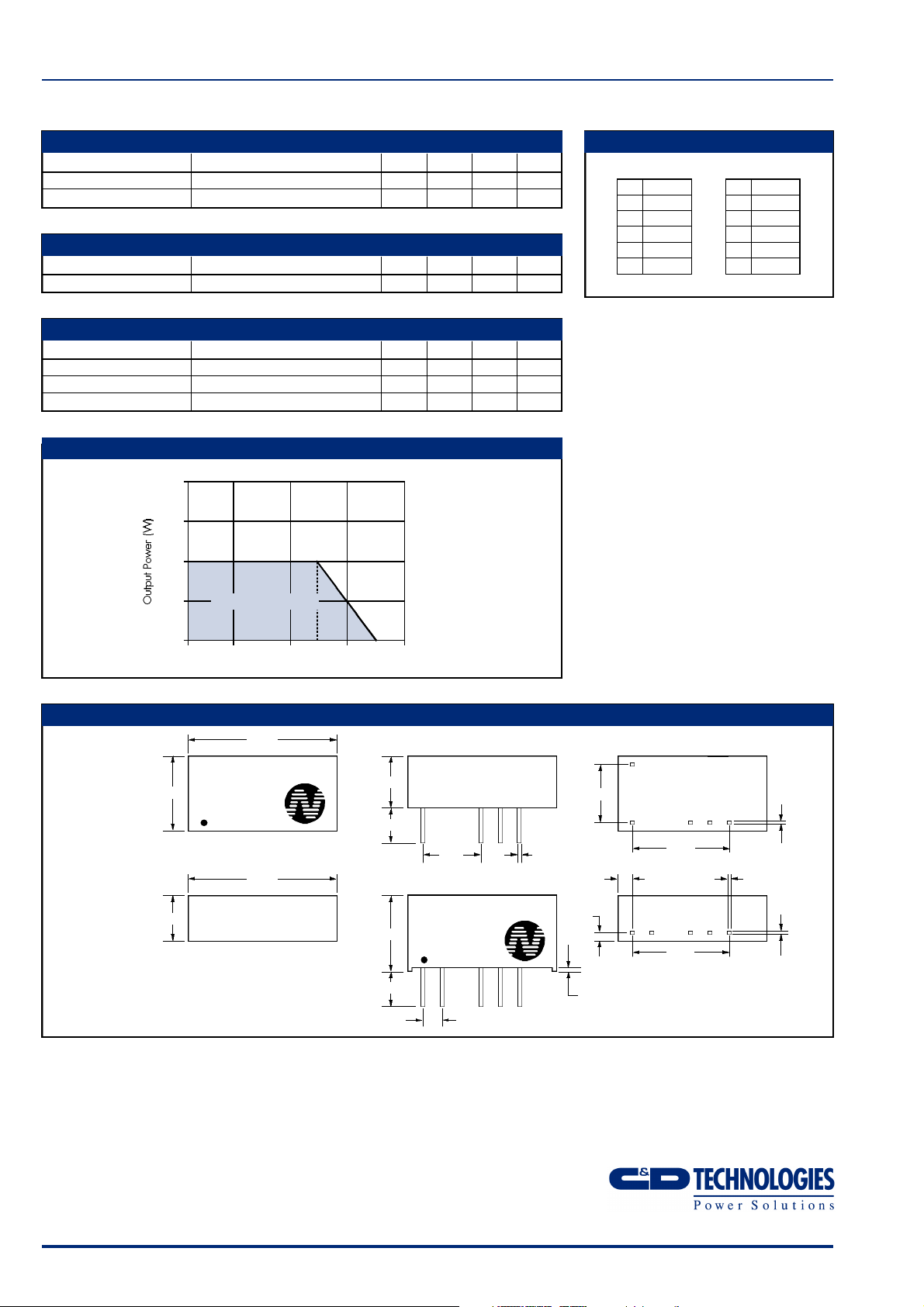
PERFORMANCE CHARACTERISTICS
temperature derating graph
2.0
1.5
1.0
PIN CONNECTIONS
14 Pin DIP
PIN
1 GND
9 +V REG
10 CTRL
11 0V
14 V
IN
7 Pin SIP
PIN
1 V
2 GND
4 0V
5 CTRL
6 +V REG
IN
0.5
Safe Operating Area
0
–40 0 50 70 100 125 150
Ambient Temperature (°C)
MECHANICAL DIMENSIONS
14 Pin DIP
Weight: 2.9g
NMF1205D
9.80
7 Pin SIP
Weight: 2.3g
6.00**
* 7.70 for 48V input variants
** 7.50 for 48V input variants
All dimensions in mm XX.XX ±0.25mm. All pins on a
2.54mm pitch and within ±0.25mm of true position.
YYWW
19.50
19.50
6.80*
4.10
10.0
4.10
7.62
NMF1212S
YYWW
1 2 5 64
2.54
0.50±0.05
7.62
1.25
0.50±0.05
1
911 1014
12.70
2.00
12.70
0.25±0.05
0.50±0.05
0.25±0.05
C&D Technologies (NCL) Limited reserve the right to alter or improve the
specification, internal design or manufacturing process at any time, without
notice. Please check with your supplier or visit our web site to ensure that
you have the current and complete specification for your product before use.
© C&D Technologies (NCL) Limited 2001 NDC NMF.3
No part of this publication may be copied, transmitted or stored in a
retrieval system or reproduced in any way including, but not limited to,
photography, photocopy, magnetic or other recording means, without prior
written permission from C&D Technologies (NCL) Limited.
Instructions for use are available from www.dc-dc.com
C&D Technologies (NCL) Ltd
Tanners Drive, Blakelands North
Milton Keynes MK14 5BU, England
Tel: +44 (0)1908 615232
Fax:+44 (0)1908 617545
email: info@cdtechno-ncl.com
www: http://www.dc-dc.com
C&D Technologies (NCL), Inc.
5816 Creedmoor Road, Raleigh
NC 27612, USA
Tel: +1 (919) 571-9405
Fax: +1 (919) 571-9262
email: info@us.cdtechno-ncl.com
 Loading...