

cdtechno NKE1205D, NKE1212D, NKE1215S, NKE0303D, NKE0505D Datasheet
...
NKE SERIES
Isolated Sub-Miniature 1W Single Output DC-DC Converters
www.dc-dc.com
SELECTION GUIDE
FEATURES
■ New Sub-Miniature SIP & DIP Styles
■ 3kVDC Isolation
■ Efficiency to 81%
■ Wide Temperature performance at
full 1 Watt load, –40°C to 85°C
■ Increased Power Density to
1.95W/cm
3
■ UL 94V-0 Package Material
■ Footprint 0.69cm
2
■ Single Isolated Output
■ Industry Standard Pinout
■ 3.3V, 5V & 12V Input
■ 3.3V, 5V, 9V, 12V and 15V Output
■ No Heatsink Required
■ Internal SMD Construction
■ Fully Encapsulated with Toroidal
Magnetics
■ No External Components Required
■ MTTF up to 2.4 Million hours
■ Custom Solutions Available
■ No Electrolytic or Tantalum
Capacitors
DESCRIPTION
The NKE sub-miniature series of DC-DC
Converters is particularly suited to isolating
and/or converting DC power rails. A smaller
package size, improved efficiency, lower
output ripple and 3kVDC isolation capability
through state of the art packaging and
improved technology. The galvanic isolation
allows the device to be configured to provide
an isolated negative rail in systems where
only positive rails exist. The wide temperature
range guarantees startup from –40°C and full
1 watt output at 85°C.
Nominal Input
Input Output Output Current at Isolation
Voltage Voltage Current Rated Load Efficiency Capacitance MTTF
1
OrderCode†(V) (V) (mA) (mA) (%) (pF) kHrs
NKE0303S 3.3 3.3 303 400 75 30 1234
NKE0305S 3.3 5 200 400 76 35 632
NKE0503S
5 3.3 303 270 75 40 619
NKE0505SE
5 5 200 250 78 34 419
NKE0505S
5 5 200 289 69 28 2414
NKE0509S
5 9 111 266 75 29 1173
NKE0512S
5 12 83 260 77 30 633
NKE0515S
5 15 66 256 78 32 360
NKE1205S
12 5 200 117 71 35 620
NKE1209S
12 9 111 107 78 50 488
NKE1212S
12 12 83 105 79 57 360
NKE1215S
12 15 66 103 81 60 252
† For DIP package style replace suffix S with D, eg NKE0303D.
When operated with additional external load capacitance the rise time of the input voltage will determine the
maximum external capacitance value for guaranteed start up. The slower the rise time of the input voltage the
greater the maximum value of the additional external capacitance for reliable start up.
1 Calculated using MIL-HDBK-217F with nominal input voltage at full load.
2 See derating curve.
3 12V input types have typically 3% less load regulation change.
4 Supply voltage must be discontinued at the end of the short circuit duration.
All specifications typical at TA=25°C, nominal input voltage and rated output current unless otherwise specified.
Parameter Conditions MIN TYP MAX Units
Continuous operation, 3.3V input types 2.97 3.3 3.63
Voltage Range Continuous operation, 5V input types 4.5 5.0 5.5
Continuous operation, 12V input types 10.8 12.0 13.2 V
Reflected Ripple Current 40 60 mA p-p
Short circuit duration
4
1 second
Internal power dissipation 530mW
Lead temperature 1.5mm from case for 10 seconds 300°C
Input voltage VinNKE03 types 5.5V
Input voltage VinNKE05 types 7V
Input voltage VinNKE12 types 15V
INPUT CHARACTERISTICS
ABSOLUTE MAXIMUM RATINGS
Parameter Conditions TYP MAX Units
Rated Power
2
TA= –40°C to 85°C 1 W
Voltage Set Point
Accuracy
See tolerance envelope
Line regulation High VINto low V
IN
1.0 1.2 %/%
10% load to rated load, 3.3V output types 10 15
10% load to rated load, 5V output types 12 15
Load Regulation310% load to rated load, 9V output types 7.5 10 %
10% load to rated load, 12V output types 6.5 9.5
10% load to rated load, 15V output types 6.0 8.5
BW=DC to 20MHz, 3.3V output types 40 80
BW=DC to 20MHz, 5V output types 77 100
Ripple and Noise BW=DC to 20MHz, 9V output types 43 90 mV p-p
BW=DC to 20MHz, 12V output types 35 65
BW=DC to 20MHz, 15V output types 32 55
OUTPUT CHARACTERISTICS
NKE SERIES
Isolated Sub-Miniature 1W Single Output DC-DC Converters
C&D Technologies (NCL) Ltd
Tanners Drive, Blakelands North
Milton Keynes MK14 5BU, England
Tel: +44 (0)1908 615232
Fax:+44 (0)1908 617545
email: info@cdtechno-ncl.com
www: http://www.dc-dc.com
C&D Technologies (NCL), Inc.
5816 Creedmoor Road, Raleigh
NC 27612, USA
Tel: +1 (919) 571-9405
Fax: +1 (919) 571-9262
email: info@us.cdtechno-ncl.com
C&D Technologies (NCL) Limited reserve the right to alter or improve the
specification, internal design or manufacturing process at any time, without
notice. Please check with your supplier or visit our web site to ensure that
you have the current and complete specification for your product before use.
© C&D Technologies (NCL) Limited 2001 NDC NKE.5
No part of this publication may be copied, transmitted or stored in a
retrieval system or reproduced in any way including, but not limited to,
photography, photocopy, magnetic or other recording means, without prior
written permission from C&D Technologies (NCL) Limited.
Instructions for use are available from www.dc-dc.com
ISOLATION CHARACTERISTICS TEMPERATURE CHARACTERISTICS
GENERAL CHARACTERISTICS
TEMPERATURE CHARACTERISTICS
PERFORMANCE CHARACTERISTICS
Parameter Conditions MIN TYP MAX Units
Isolation Test Voltage Flash tested for 1 second 3000 VDC
Resistance Viso=500VDC 10 GΩ
Parameter Conditions MIN TYP MAX Units
Switching Frequency All input types 115 kHz
Parameter Conditions MIN TYP MAX Units
Specification All output types -40 85 °C
Storage -50 130 °C
Case Temperature
0505D/S, 1205D/S 41
°C
above ambient
A
ll other output types 32
Cooling Free air convection
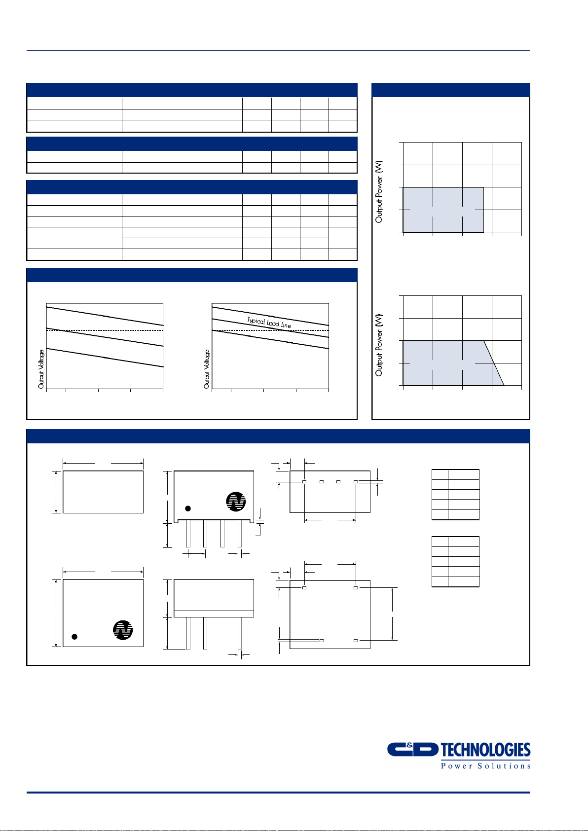
6.00
MECHANICAL DIMENSIONS
7.46
4.60
3.60
112 3 4
0.30
0.20
0.55
0.45
0.50±0.05
4 Pin SIP
PIN
1 GND
2 V
IN
3 0V
4 +V
8 Pin DIP
PIN
1 GND
4 V
IN
5 +V
7 0V
Weight:1.09g
All dimensions in mm XX.XX
±0.25mm. All pins on a
2.54mm pitch and within
±0.25mm of true position.
2.54
11.48 2.18±0.501.25
7.62
NKE0505S
XYYWW
0.30
0.20
1.94 1.09
7.62
5.40
4.60
3.60
0.50±0.05
9.80
11.50
8 Pin DIP Package Style
4 Pin SIP Package Style
NKE0505D
XYYWW
4
57
7.62
10 25 50 75 100
Output Load Current (%)
tolerance envelope (3.3V output types)
+9%
+1%
V
NOM
-7%
+1%
–7%
–15%
10 25 50 75 100
Output Load Current (%)
tolerance envelope (all other types)
Temperature Derating Graph
NKE 0303D/S, 0305D/S,
0503D/S, 0505DE/SE Types
Ambient Temperature (°C)
85°C
2.0
1.5
1.0
0.5
0
+10%
+5%
V
NOM
+2.5%
–2.5%
–7.5%
Safe Operating Area
-40 0 50 100 150
Temperature Derating Graph
All other types
Ambient Temperature (°C)
85°C
120°C
2.0
1.5
1.0
0.5
0
Safe Operating Area
-40 0 50 100 150
 Loading...