

cdtechno NDY1215, NDY2409, NDY2405, NDY0515, NDY1212 Datasheet
...
www.cdpoweronline.com
SELECTION GUIDE
FEATURES
■ Industry Standard Footprint
■ Single Isolated Output
■ Short Circuit Protection
■ Operating Temperature Range
-40°C to +85°C
■ Low Profile 24 Pin Case
■ Efficiency to 82%
■ Power Density 0.90W/cm
3
■ 2:1 Wide Input Range
■ 5V, 12V, 24V & 48V Input
■ 3.3V, 5V, 9V, 12V & 15V Output
■ Footprint 4.73cm
2
■ UL 94V-0 Package Materials
■ No Heatsink Required
■ Internal SMD Construction
■ Fully Encapsulated
■ Lead Free Compatible
DESCRIPTION
The NDY series is a range of low profile
DC/DC converters offering a single regulated
output over a 2:1 input voltage range. All
parts deliver 3W output power up to 85°C
without heatsinking, except the 4.5V to 9V
input voltage range which should be derated
to 2W at the lower input voltage. A flyback
oscillator design with isolated feedback is
used to give regulation over the full operating
range of 25% to 100% of full load. It is
strongly recommended that external
capacitors be used on input and output to
guarantee performance over full load and
input voltage range (see recommended filter
circuit for values). The plastic case and
encapsulant materials are rated to UL 94V-0
and the connection pins are formed from a
tin plated alloy 42 leadframe.
Nominal Rated
Input
Input Output
Output Current
4
Current
Voltage Voltage Min Load Full Load Full Load MTTF
3
Order Code (V) (V) (mA) (mA) (mA) (%) (pF) kHrs
NDY0505 55100 -150 400- 600 615 66 40 1939
NDY0509
5955-83 222-333 563 72 52 1926
NDY0512
5 12 42-62 166-250 548 71 43 1907
NDY0515
51533-50 133-200 533 73 44 1924
NDY1205
12 5 150 600 362 71 36 1928
NDY1209 12 9 83 333 320 78 52 1916
NDY1212 12 12 62 250 316 78 44 1897
NDY1215 12 15 50 200 308 79 47 1914
NDY2403 24 3.3 227 909 178 70 30 1671
NDY2405
24 5 150 600 174 70 36 1673
NDY2409
24 9 83 333 156 78 52 1663
NDY2412
24 12 62 250 154 80 44 1644
NDY2415
24 15 50 200 150 82 54 1657
NDY4803 48 3.3 227 909 87 71 30 1676
NDY4805 48 5 150 600 87 73 35 1668
NDY4809 48 9 83 333 78 80 52 1663
NDY4812 48 12 62 250 77 81 44 1648
NDY4815 48 15 50 200 76 81 53 1661
Min
Efficiency1Typical
Isolation
Capacitance
Parameter Conditions MIN TYP MAX Units
All NDY05XX 4.5 5 9
Voltage Range
All NDY12XX 9 12 18
VDC
All NDY24XX 18 24 36
All NDY48XX 36 48 72
NDY2403
2
180 360
NDY4803
2
140 290
Reflected
1
All NDY05XX 400 500
Ripple
All NDY12XX 150 170
mA p-p
Current
All other NDY24XX 290 360
All other NDY48XX 100 127
Short-circuit protection continuous
Input voltage 05 types 10V
Input voltage 12 types 20V
Input voltage 24 types 40V
Input voltage 48 types 80V
Lead temperature 1.5mm from case for 10 seconds 300°C
Minimum Load 25% of rated load
Internal Dissipation 1.7W
INPUT CHARACTERISTICS
ABSOLUTE MAXIMUM RATINGS
1 Measured at full load with external input/output capacitors, refer to filter circuit 1.
2 For lower ripple refer to filter circuit 2.
3 Calculated using MIL-HDBK-217F with nominal input voltage at full load.
4 Refer to power derating graph.
All specifications typical at T
A
=25°C, nominal input voltage and rated output current unless otherwise specified.
NDY SERIES
Isolated 3W Wide Input DC/DC Converters
Parameter Conditions MIN TYP MAX Units
Voltage Set Point Accuracy With external input/output capacitors, refer to filter circuits ±1 ±5 %
Low line to high line, 3.3V output with external input/output capacitors,
0.05 0.2 %
Line Regulation
refer to filter circuit 1
Low line to high line, with external input/output capacitors,
0.05 0.5 %
refer to filter circuit 1
25% load to 100% load, 3.3V output with external input/output capacitors,
0.6 0.5
%
Load Regulation
refer to filter circuit 1
25% load to 100% load, with external input/output capacitors,
0.2 0.5
%
refer to filter circuit 1
BW = 20Hz to 300kHz. 3.3V output with external input/output capacitors,
80 120 mV rms
Ripple
2
refer to filter circuit 1
BW = 20Hz to 300kHz. With external input/output capacitors,
510mV rms
refer to filter circuit 1
BW = DC to 100MHz. 3.3V output with external input/output capacitors,
180 mV p-p
Noise
refer to filter circuit 1
BW = DC to 100MHz. With external input/output capacitors,
50 100 mV p-p
refer to filter circuit 1
OUTPUT CHARACTERISTICS
www.cdpoweronline.com
1 Measured at full load with external input/output capacitors, refer to filter circuit 1.
2 For lower ripple refer to filter circuit 2.
3 Calculated using MIL-HDBK-217F with nominal input voltage at full load.
4 Refer to power derating graph.
All specifications typical at T
A
=25°C, nominal input voltage and rated output current unless otherwise specified.
NDY SERIES
Isolated 3W Wide Input DC/DC Converters
ISOLATION CHARACTERISTICS
GENERAL CHARACTERISTICS
Parameter Conditions MIN TYP MAX Units
Isolation Test Voltage Flash tested for 1 second 1000 VDC
Resistance Viso=500VDC 1 GΩ
Parameter Conditions MIN TYP MAX Units
100% load VINnominal 3.3V output 160 220
Switching Frequency
25% load VINnominal 3.3V output 290 560
kHz
100% load VINnominal 80 220
25% load VINnominal 290 560
Weight: 6.2g (3.3V O/P 6.7g)
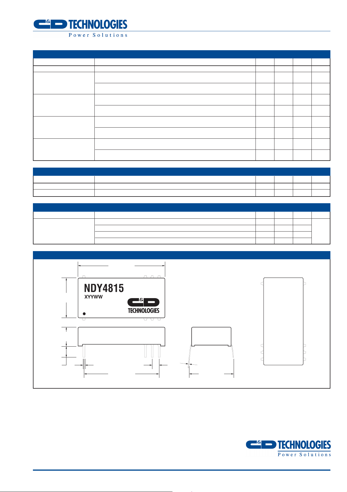
PIN CONNECTIONS (TOP VIEW)
1.27 (32.26)
0.577
(14.66)
0.275
(7.00)
0.185 (4.70)
0.145 (3.70)
0.033 (0.84)
0.021 (0.54)
0.012 (0.30)
0.008 (0.20)
124
10 15
11 14
12 13
V
IN
0V
+V
GND
V
IN
0V
+V
GND
0.10
(2.54)
1.10 (27.94) 0.644
(16.35) Max
MECHANICAL DIMENSIONS
 Loading...