

cdtechno NDTD4815, NDTD4812, NDTD2415, NDTD2412 Datasheet
NDT SERIES
Isolated 3W Wide Input Dual Output DC-DC Converters
FEATURES
■ Industry Standard Footprint
■ 1kVDC Isolation
■ Dual Isolated Output
■ Short Circuit Protection
■ Low Profile 24 Pin Case
■ Efficiency to 81%
■ Power Density 0.90W/cm
3
■ 2:1 Wide Input Range
■ 24V & 48V Input
■ 12V & 15V Output
■ Footprint 4.73cm
2
■ UL 94V-0 Package Materials
■ Operating Temperature Range
–40°C to 85°C
■ Load and Line Regulation
<1% on Both Outputs
■ No Heatsink Required
■ Internal SMD Construction
■ Fully Encapsulated
■ Custom Solutions Available
DESCRIPTION
The NDT series is a range of low profile DCDC converters offering dual outputs over a
2:1 input voltage range. All parts deliver 3W
output power up to 85°C without heatsinking.
A flyback oscillator design with isolated
feedback is used to give regulation over the
full operating range of 25% to 100% of full
load. It is strongly recommended that external
capacitors be used on input and output to
guarantee performance over full load and
input voltage range (see application notes for
guidance). The plastic case is rated to UL
94V-0 and encapsulant to UL 94V-1and the
connection pins are formed from a tin plated
alloy 42 leadframe.
www.dc-dc.com
SELECTION GUIDE
Nominal Rated
Voltage Voltage Min Load3Full Load Full Load MTTF
1
Input Output
Output Current Current
Input
Order Code (V) (V) (mA) (mA) (mA) (%) (pF) kHrs
NDTD2412
NDTD2415
NDTD4812
NDTD4815
INPUT CHARACTERISTICS
Parameter Conditions MIN TYP MAX Units
Voltage Range
Reflected Ripple
Current
OUTPUT CHARACTERISTICS
Parameter Conditions MIN TYP MAX Units
24 12 ±31 ±125 156 79 30 2075
24 15 ±25 ±100 155 80 30 2080
48 12 ±31 ±125 77 81 30 2090
48 15 ±25 ±100 77 81 30 2045
1
24V input types 18 24 36
48V input types 36 48 75
24V input types with 10µF at input 200 250
48V input types with 10µF at input 125 150
1
VDC
mA p-p
Rated Power 3 W
Voltage Set With external input/output capacitors,
Point Accuracy refer to recommended test circuit
±1 ±5 %
Low line to high line,
Line Regulation with external input/output capacitors, 0.15 0.5 %
refer to recommended test circuit
25% load to 100% load,
Load Regulation with external input/output capacitors, 0.2 0.5 %
refer to recommended test circuit
BW = 20Hz to 300kHz
Ripple With external input/output capacitors, 15 30 mV rms
refer to recommended test circuit
BW = DC to 20MHz
Ripple & Noise With external input/output capacitors, 90 150 mV p-p
refer to recommended test circuit
Cross
Regulation
% voltage change on negative output
when positive load varies from 12% to 2.1 3.0 %
50% with negative load fixed at 50%
ABSOLUTE MAXIMUM RATINGS
Short circuit protection over temperature range and input voltage range continuous
Input Voltage, 24V types 40V
Input Voltage, 48V types 80V
Lead temperature 1.5mm from case for 10 seconds 300°C
Minimum Load 25% of rated output
ISOLATION CHARACTERISTICS
Parameter Conditions MIN TYP MAX Units
Isolation Test Voltage Flash tested for 1 second 1000 VDC
Resistance Viso=1KVDC 1 GΩ
GENERAL CHARACTERISTICS
Parameter Conditions MIN TYP MAX Units
Switching Frequency
ENVIRONMENTAL
Parameter Conditions MIN TYP MAX Units
Operation –40 85 °C
Storage –50 130 °C
Case Temperature Above Ambient 100% Load 28 °C
1 Specifications typical at TA=25°C, nominal input voltage and rated output current unless otherwise specified.
2 Measured at full load with external input/output capacitors, refer to test circuit.
3 A lower load is entirely safe but higher levels of output ripple will be experienced.
4 Calculated using MIL-HDBK-217F with nominal input voltage at full load.
100% load VINnominal 100 125 150
25% load VINnominal 410 500 590
1
1
1
kHz
4
NDT SERIES
Isolated 3W Wide Input Dual Output DC-DC Converters
TERMINOLOGY
LINE REGULATION
The percentage change in output voltage between low input voltage and high input voltage,
measured with fixed output load
ie. A 5V output part with an output voltage of 5.05V @ high input voltage and 5.03V @
low input voltage would have a line regulation of 0.4%.
V
line regulation =
Where V
(Nominal Input V) is 5V.
OUT
(Low Input V) –V
OUT
V
OUT
(Nominal Input V)
(High Input V)
OUT
x100%
APPLICATION NOTES
EXTERNAL CAPACITANCE
Although these converters will work
without external capacitors, they are
necessary in order to guarantee the full
parametric performance over the
full line and load range. All parts have
been tested and characterised
using the following values and test circuit
Value
C
IN
10µF, 200V 47µF, 25V
C
OUT
TEST CIRCUIT
V
IN
C
IN
GND
NDT
+V
C
OUT
0V
C
OUT
–V
OUT
OUT
PIN CONNECTIONS
24 Pin DIL (top view)
–V
–V
Common
–V
OUT
2 23
IN
3 22
IN
9 16
11 14
+V
IN
+V
IN
Common
+V
OUT
PACKAGING DETAILS
Order Code Packaging Style QTY
NDTDXXXX Tube 15
TUBE OUTLINE DIMENSIONS
0.657±0.022
(16.70±0.55)
0.815±0.022
(20.70±0.55)
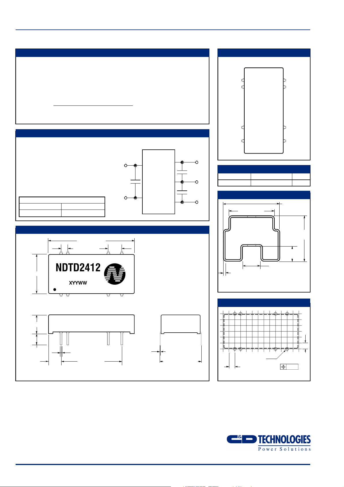
MECHANICAL DIMENSIONS
1.270(32.26)
0.100(2.54)
0.577(14.66)
0.275(7.00)
0.185(4.70)
0.145(3.70)
0.185
(4.70)
Weight: 6.5g Unless otherwise stated all dimensions in inches ±0.010 (mm ±0.25mm).
C&D Technologies (NCL) Limited reserve the right to alter or improve the
specification, internal design or manufacturing process at any time, without
notice. Please check with your supplier or visit our web site to ensure that
you have the current and complete specification for your product before use.
© C&D Technologies (NCL) Limited 2002 NDC NDT.1
No part of this publication may be copied, transmitted or stored in a
retrieval system or reproduced in any way including, but not limited to,
photography, photocopy, magnetic or other recording means, without prior
written permission from C&D Technologies (NCL) Limited.
Instructions for use are available from www.dc-dc.com
0.033(0.84)
0.021(0.54)
0.900(22.86)
0.200
(5.08)
0.012(0.30)
0.008(0.20)
0.600(15.25)Max
C&D Technologies (NCL) Ltd
Tanners Drive, Blakelands North
Milton Keynes MK14 5BU, England
Tel: +44 (0)1908 615232
Fax:+44 (0)1908 617545
email: info@cdtechno-ncl.com
www: http://www.dc-dc.com
0.657±0.031
(16.70±0.80)
0.217±0.001
(5.50±0.25)
0.268±0.022
0.031±0.006
(0.80±0.15)
Tube Length: 20.472±0.079(520mm±2mm)
Tube Material: Antistatic coated clear pvc.
6.80±0.55
RECOMMENDED FOOTPRINT DETAILS
Ø0.1
0.100
(2.54)
0.057(1.45)
Ø
0.051(1.30)
0.100(2.54)
All pins on a 0.100(2.54) pitch
and within 0.010(0.25) of true position.
C&D Technologies Inc.
3400 E Britannia Drive, Tucson,
Arizona 85706, USA
Tel: +1 (800) 547-2537
Fax: +1 (520) 741-4598
email: sales@cdtechno.com
8 Holes
 Loading...