

Page 1

User Manual
UPO 11-1-1.5-2-3 (AX) UPO 11-1RT,
1.5RT, 2RT, 3RT PF1.0
Customer Made - COLOMBIA
Rack/Tower Online UPS
Uninterruptible Power Supply System
Version: 1.0 2017
Page 2

Table of Contents
1. Important Safety Warning....................................................................1
1-1. Transportation..........................................................................................1
1-2. Preparation................................................................................................1
1-3. Installation................................................................................................1
1-4. Operation..................................................................................................1
1-5. Maintenance, service and faults...................................................................2
2. Installation and setup...........................................................................4
2-1. Rear panel view.........................................................................................4
2-2. Operating principle.....................................................................................5
2-3. Install the UPS...........................................................................................6
2-4. Setup the UPS............................................................................................7
2-5. Battery Replacement..................................................................................9
2-6 Battery Kit Assembly (option).....................................................................11
3. Operations...........................................................................................13
3-1. Button operation......................................................................................13
3-2. LCD Panel................................................................................................13
3-3. Audible Alarm...........................................................................................15
3-4. LCD display wordings index.......................................................................15
3-5. UPS Setting..............................................................................................15
3-6. Operating Mode Description......................................................................21
3-7. Faults Reference Code..............................................................................22
3-8. Warning indicator.....................................................................................23
4. Troubleshooting..................................................................................24
5. Storage and Maintenance....................................................................25
6. Specifications.......................................................................................26
Page 3

1. Important Safety Warning
Please comply with all warnings and operating instructions in this manual strictly. Save this manual
properly and read carefully the following instructions before installing the unit. Do not operate this
unit before reading through all safety information and operating instructions carefully.
1-1. Transportation
Please transport the UPS system only in the original package to protect against shock and
impact.
1-2. Preparation
Condensation may occur if the UPS system is moved directly from cold to warm
environment. The UPS system must be absolutely dry before being installed. Please allow
at least two hours for the UPS system to acclimate the environment.
Do not install the UPS system near water or in moist environments.
Do not install the UPS system where it would be exposed to direct sunlight or near heater.
Do not block ventilation holes in the UPS housing.
1-3. Installation
Do not connect appliances or devices which would overload the UPS system (e.g. laser
printers) to the UPS output sockets.
Place cables in such a way that no one can step on or trip over them.
Do not connect domestic appliances such as hair dryers to UPS output sockets.
The UPS can be operated by any individuals with no previous experience.
Connect the UPS system only to an earthed shockproof outlet which must be easily
accessible and close to the UPS system.
Please use only VDE-tested, CE-marked (or UL-marked for 100/110/115/120/127 VAC
models) mains cable (e.g. the mains cable of your computer) to connect the UPS system
to the building wiring outlet (shockproof outlet).
Please use only VDE-tested, CE-marked (or UL-marked for 100/110/115/120/127 VAC
models) power cables to connect the loads to the UPS system.
When installing the equipment, it should ensure that the sum of the leakage current of the
UPS and the connected devices does not exceed 3.5mA.
Temperature Rating - Units are considered acceptable for use in a maximum ambient of
40°C (104°F). This UPS can be used in special cabbinets without batteries until 60°C (140°F).
For Pluggable Equipment - The socket-outlet shall be installed near the equipment and
shall be easily accessible.
1-4. Operation
Do not disconnect the mains cable on the UPS system or the building wiring outlet
(shockproof socket outlet) during operations since this would cancel the protective
earthing of the UPS system and of all connected loads.
The UPS system features its own, internal current source (batteries). The UPS output
sockets or output terminals block may be electrically live even if the UPS system is not
connected to the building wiring outlet.
Page 4

In order to fully disconnect the UPS system, first press the OFF/Enter button to disconnect
the mains.
Prevent no fluids or other foreign objects from inside of the UPS system.
1-5. Maintenance, service and faults
The UPS system operates with hazardous voltages. Repairs may be carried out only by
qualified maintenance personnel.
Caution - risk of electric shock. Even after the unit is disconnected from the mains
(building wiring outlet), components inside the UPS system are still connected to the
battery and electrically live and dangerous.
Before carrying out any kind of service and/or maintenance, disconnect the batteries and
verify that no current is present and no hazardous voltage exists in the terminals of high
capability capacitor such as BUS-capacitors.
Only persons are adequately familiar with batteries and with the required precautionary
measures may replace batteries and supervise operations. Unauthorized persons must be
kept well away from the batteries.
Caution - risk of electric shock. The battery circuit is not isolated from the input voltage.
Hazardous voltages may occur between the battery terminals and the ground. Before
touching, please verify that no voltage is present!
Caution-Do not dispose of batteries in a fire. The batteries may explode.
Caution-Do not open or mutilate batteries. Released electrolyte is harmful to the skin and
eyes. It may be toxic.
Batteries may cause electric shock and have a high short-circuit current. Please take the
precautionary measures specified below and any other measures necessary when working
with batteries:
a) Remove watches, rings, or other metal objects.
b) Use tools with insulated handles.
c) Wear rubber gloves and boots.
d) Do not lay tools or metal parts on top of batteries.
e) Disconnect charging source and load prior to installing or maintaining the battery.
f) Remove battery grounds during installation and maintenance to reduce likelihood of
shock. Remove the connection from ground if any part of the battery is determined to
be grounded.
When changing batteries, install the same number and same type of batteries or battery
packs.
Page 5

Manufacture
Type
Rated
Toplite (Guangzhou)
Technology Battery Co Ltd
(MH29104)
NPW45-12
12V dc, 9.0 Ah
UXW460-12
12V dc, 9.0 Ah
NPW36-12
12V dc, 7.2 Ah
UXW360-12
12V dc, 7.2 Ah
NPW45-12 FR
12V dc, 7.0 Ah
UXW460-12 / FR
12V dc, 7.0 Ah
NPW36-12 FR
12V dc, 7.0 Ah
CSB Battery Co Ltd
(MH14533)
UXW460-12 / FR
12V dc, 7.0 Ah
GP1272
12V dc, 7.2 Ah
UPS 12460 F2
12V dc, 9.0 Ah
UPS 12360 6
12V dc, 6.5 Ah
UPS 12360 7
12V dc, 6.5 Ah
HR 1234W
12V dc, 8.5 Ah
HR 1234W FR
12V dc, 8.5 Ah
Yuasa Battery (Guandong)
Co Ltd (MH29616)
NPW45-12
12V dc, 8.0 Ah
NPW45-12 FR
12V dc, 8.0 Ah
For UPS with internally mounted battery
a) Instructions shall carry sufficient information to enable the replacement of the battery
with a suitable manufacturer and catalogue number.
b) Safetyinstructions to allow access by Service Personnel shall be stated in the
installation/service handbook.
c) If batteries are to be installed by Service Personnel, instructions for interconnections,
including terminal torque, shall be provided.
Do not attempt to dispose of batteries by burning them. This could cause battery
explosion.
Do not open or destroy batteries. Escaping electrolyte can cause injury to the skin and
eyes. It may be toxic.
Please replace the fuse only with the same type and amperage in order to avoid fire
hazards.
Do not dismantle the UPS system.
Page 6
2. Installation and setup
NOTE: Before installation, please inspect the unit. Be sure that nothing inside the package is
damaged. Please keep the original package in a safe place for future use. OPTIONAL: If the end
user wants other cases for application outdoor, it is posible to change the cases; consult your
dealer.
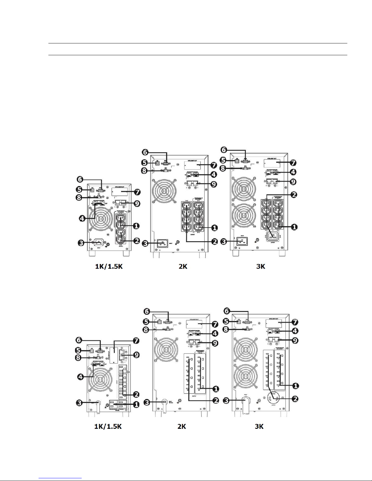
2-1. Rear panel view
Tower Models
IEC Type
NEMA Type
Page 7
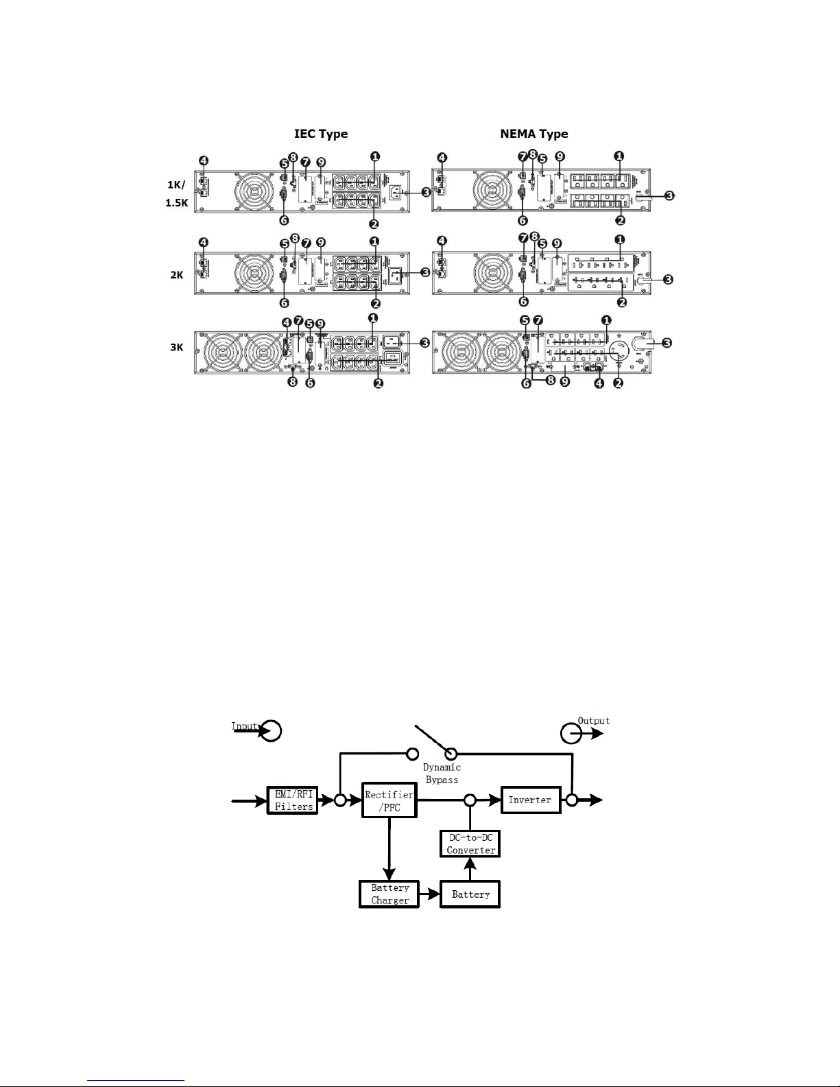
RT Models
1. Programmable outlets: connect to non-critical loads.
2. Output receptacles: connect to mission-critical loads.
3. AC input
4. Network/Fax/Modem surge protection
5. USB communication port
6. RS-232 communication port
7. SNMP intelligent slot
8. Emergency power off port (EPO)
9. External battery connection
2-2. Operating principle
The operating principle of the UPS is shownas below
The UPS is composed of mains input, EMI/RFI filters, rectifier/PFC, inverter, battery
charger, DC-to-DC converter,battery, dynamic bypass and UPS output.
Page 8
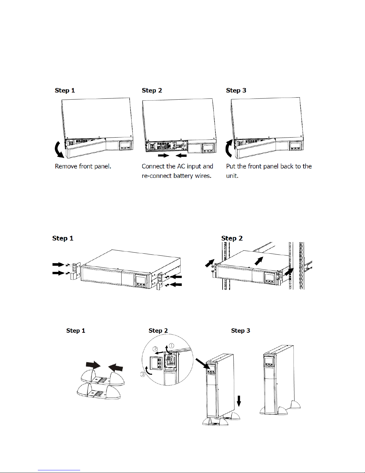
2-3. Install the UPS(Only for RT Models)
For safety consideration, the UPS is shipped out from factory without connecting battery
wires. Before install the UPS, please follow below steps to re-connect battery wires first.
This UPS can be either displayed on the desk or mounted in the 19” rack chassis. Please
choose proper installation to position this UPS.
Rack-mount Installation
Tower Installation
Page 9
2-4. Setup the UPS
Before installing the UPS, please read below to select proper location to install UPS.
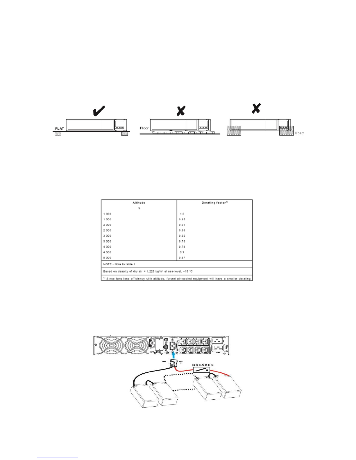
1. UPS should be placed on the flat and clean surface. Place it in an area away from
vibration, dust, humidity, high temperature, flammable liquids, gases, corrosive and
conductive contaminants. For options outdoor please consult our local office. Install
the UPS indoors in a clean environment, where it is away from window and door.
Maintain minimum clearance of 100mm in the bottom of the UPS to avoid dust and
high temperature.
2. Maintain an ambient temperature range of 0ºC to 45ºC for UPS optimal
operation. For every 5ºC above 45ºC, the UPS will derate 12% of nominal capacity
at full load. The highest working temperature requirement for UPS operation is 60ºC.
3. It’s required to maintain maximum altitude of 1000m to keep UPS normal operation
at full load UPS. If it’s used in high altitude area, please reduce connected load.
Altitude derating power with connected loads for UPS normal operation is listed as
below:
4. Place UPS: It’s equipped with fan for cooling. Therefore, place the UPS in a well-
ventilated area. It’s required to maintain minimum clearance of 100mm in the front
of the UPS and 300mm in the back and two sides of the UPS for heat dissipation
and easy- maintenance.
5.Connect to External Battery Pack
Page 10
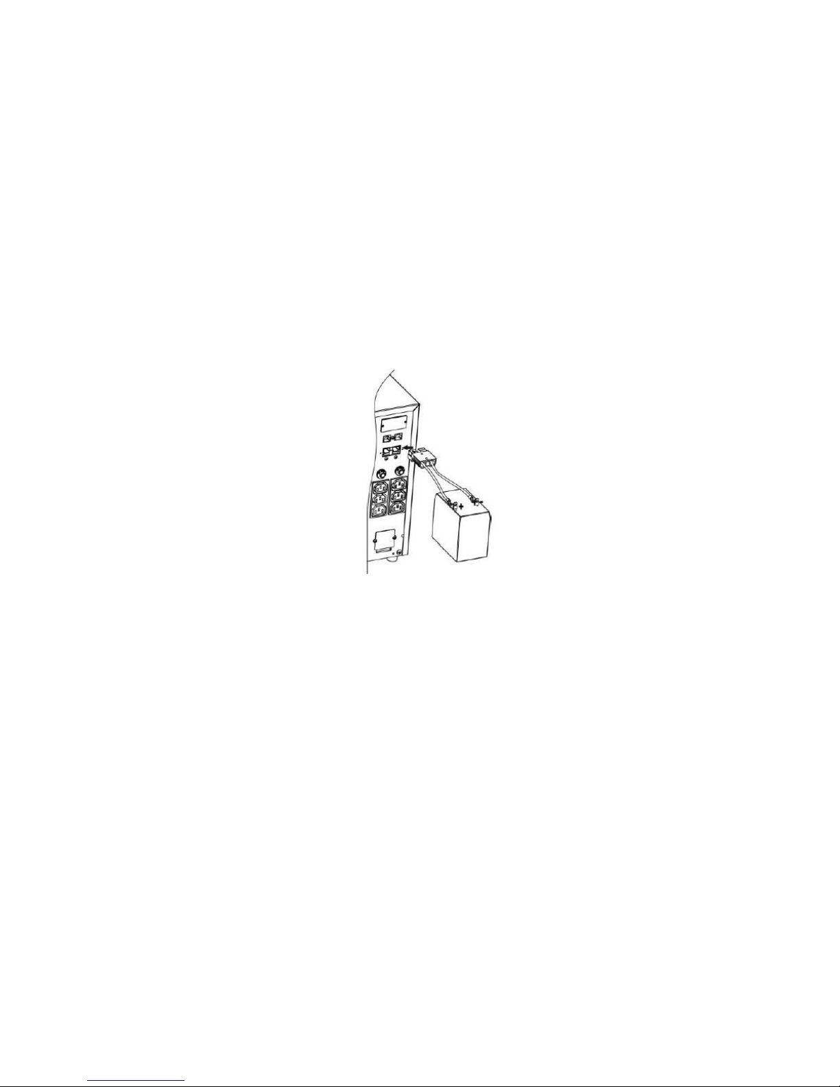
When connecting external battery packs, please be sure to connect polarity correctly.
Connect positive pole of battery pack to positive pole of external battery connector in UPS
and negative pole of battery pack to negative pole of external battery connector in UPS.
Polarity misconnection will cause UPS internal fault. It’s recommended to add one breaker
between positive pole of battery pack and positive pole of external battery connector in
UPS to prevent damage to battery packs from internal fault.
The required specification of breaker: voltage ≧ 1.25 x battery voltage/set; current ≧ 50A
Please choose battery size and connected numbers according to backup time requirement
and UPS specifications. To extend battery lifecycle, it’s recommended to use them in the
temperature range of 15ºC to 25ºC. The operation the UPS without batteries is from -30°C
to 60°C.
Step 1: External battery connection
Followthe right chart to make external battery connection.
Step 2: UPS input connection
Plug the UPS into a two-pole, three-wire, grounded receptacle only. Avoid using extension
cords.
For 200/208/220/230/240VAC models: The power cord is supplied in the UPS package.
For 100/110/115/120/127VAC models: The power cord is attached to the UPS. The
input plug is a NEMA 5-15P for 1K and 1.5K models, NEMA 5-20P for 2K model and
NEMA 5-30P for 3K model.
Note:Check if the site wiring fault indicator lights up in LCD panel. It will be illuminated
when the UPS is plugged into an improperly wired utility power outlet (Refer to
Troubleshooting section). Please also check if there is a circuit breaker installed between
the mains and AC input of the UPS against overcurrent and short circuit for safety
operation. The recommended protection specification is listed as following:
For 200/208/220/230/240VAC models: 10A for the 1K and 1.5K models, 16A for the 2K
and 3K models.
For 100/110/115/120/127VAC models: 15A for the 1K and 1.5K models, 20A for 2K
model and 30A for 3K model.
Step 3: UPS output connection
There two kinds of outputs: programmable outlets and general outlets. Please connect noncritical devices to the programmable outlets and critical devices to the general outlets.
Page 11
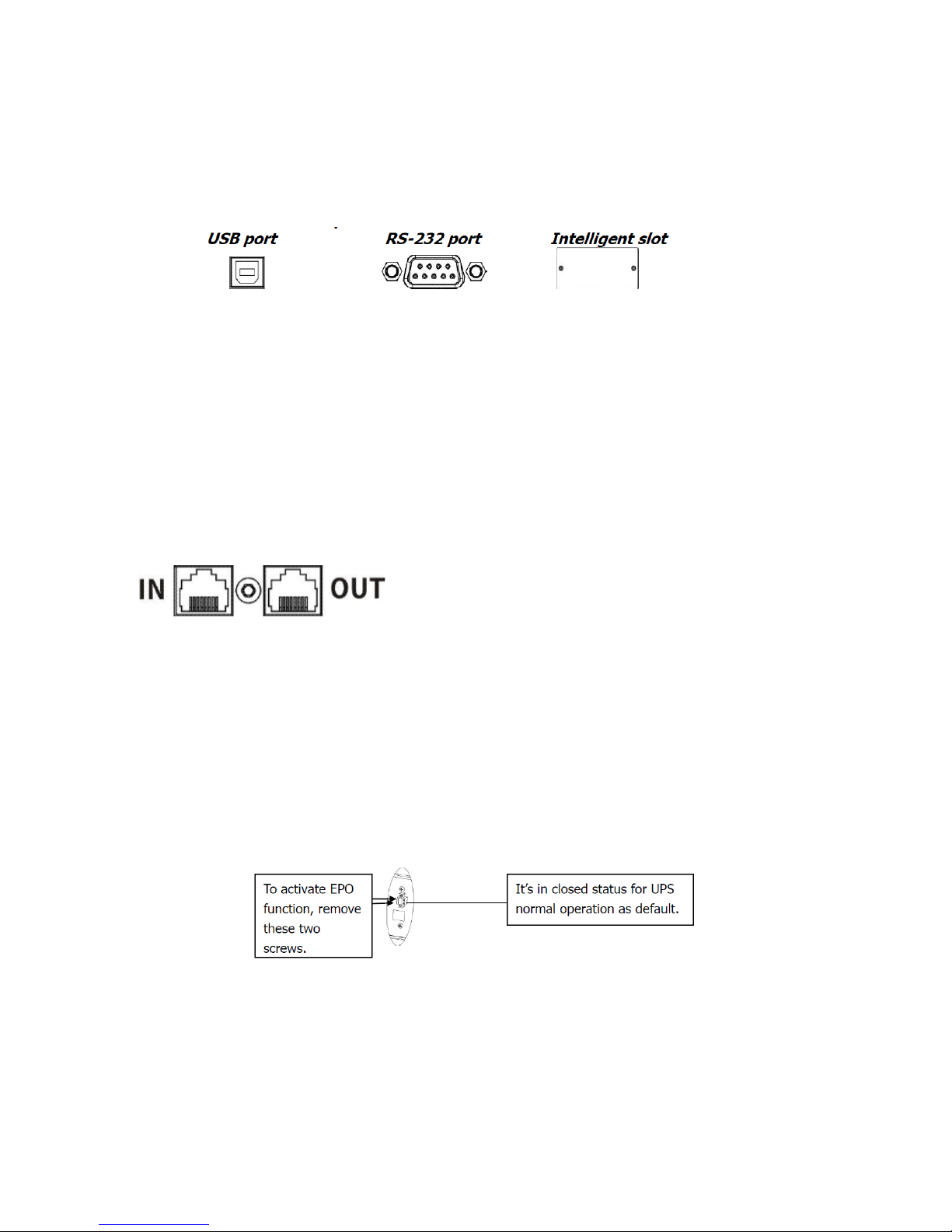
During power failure, you may extend the backup time to critical devices by setting shorter
backup time for non-critical devices.
Step 4: Communication connection
Communication port:
To allow for unattended UPS shutdown/start-up and status monitoring, connect the
communication cable one end to the USB/RS-232port and the other to the communication
port of your PC. With the monitoring software installed, you can schedule UPS
shutdown/start-up and monitor UPS status through PC.
The UPS is equipped with intelligent slot perfect for either UPO SNMP or SNMP web card
box or CDP AS400 card (dry contacts). When installing either UPO SNMP or SNMP web card
box or CDP AS400 card (dry contacts) in the UPS, it will provide advanced communication
and monitoring options.
Step 5: Network connection
Network/Fax/Phone surge port
Connect a single modem/phone/faxline into surge-protected “IN” outlet on the back panel
of the UPS unit. Connect from “OUT” outlet to the equipmentwith another
modem/fax/phone line cable.
Step 6: Disable and enable EPO function
This UPS is equipped with EPO function. By default, the UPS is delivered from factory with
Pin 1 and pin 2 closed (a metal plate is connected to Pin 1 and Pin2) for UPS normal
operation. To activate EPO function, remove two screws on EPO port and metal plate will
be removed.
Note: The EPO function logic can be set up via LCD setting. Please refer to program 16 in
UPS setting for the details.
Step 7: Turn on the UPS
Press the ON/Mute button on the front panel for two seconds to power on the UPS.
Note: The battery charges fully during the first five hours of normal operation. Do not
expect full battery run capability during this initial charge period.
Page 12

Step 8: Install software
For optimal computer system protection, install UPS monitoring software to fully configure
UPS shutdown. Use supplied RS-232 or USB communication cable to connect RS-232/USB
port of UPS and RS-232/USB port of PC. Then, follow below steps to install monitoring
software.
1. Insert the included installation CD into CD-ROM drive and then follow the on-
screen instructions to proceed software installation. If there no screen shows 1
minute after inserting the CD, please execute setup.exe file for initiating software
installation.
2. Follow the on-screen instructions to install the software.
3. When your computer restarts, the monitoring software will appear as an orange
plug icon located in the system tray, near the clock.
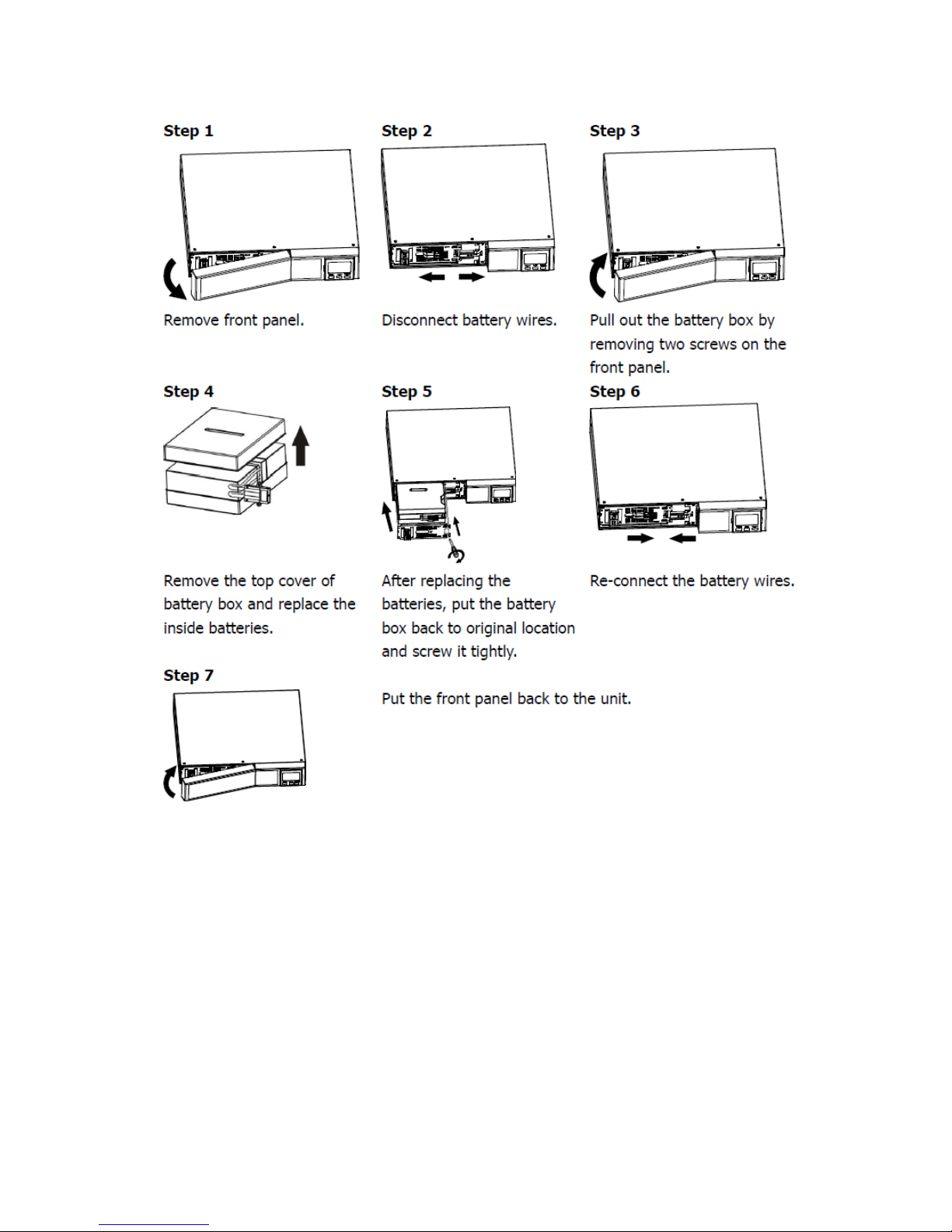
2-5. Battery Replacement (Only for RT Models)
NOTICE: This UPS is equipped with internal batteries and user can replace the batteries
without shutting down the UPS or connected loads. (hot-swappable battery design)
Replacement is a safe procedure, isolated from electrical hazards.
CAUTION! Consider all warnings, cautions, and notes before replacing batteries.
Note: Upon battery disconnection, equipment is not protected from power outages.
Page 13
2-6 Battery Kit Assembly (option)
NOTICE:Please assemble battery kit first before installing it inside of UPS. Please select
correct battery kit procedure below to assemble it.
Page 14
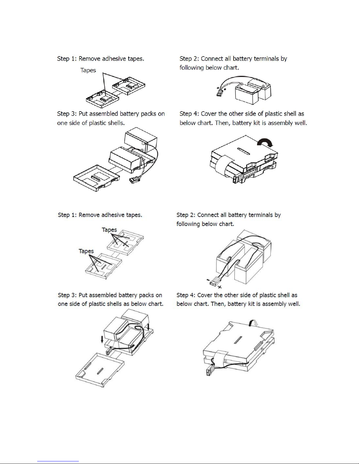
2-Battery kit
3-Battery kit
Page 15
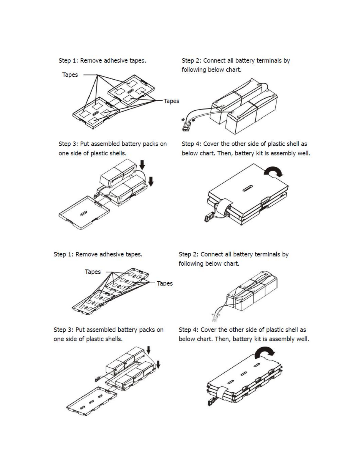
4-Battery kit
5-Battery kit
Page 16
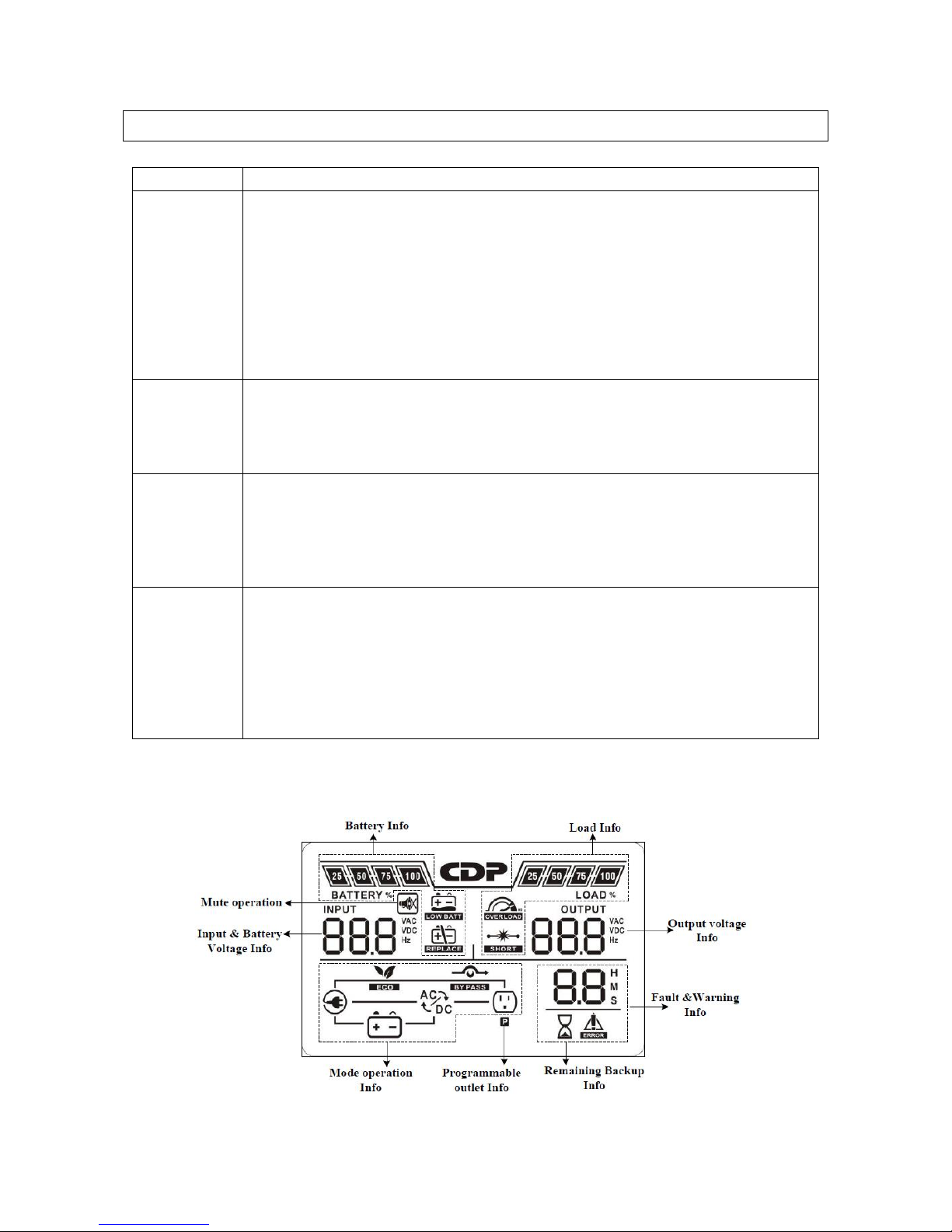
3.Operations
Button
Function
ON/Mute
Button
Turn on the UPS: Press and hold ON/Mute button for at least 2 seconds
to turn on the UPS.
Mute the alarm: After the UPS is turned on in battery mode, press and
hold this button for at least 3 seconds to disable or enable the alarm
system. But it’s not applied to the situations when warnings or errors
occur.
Up key: Press this button to display previous selection in UPS setting
mode.
Switch to UPS self-test mode: Press ON/Mute buttons for 3 seconds to
enter UPS self-testing while in AC mode, ECO mode, or converter mode.
OFF/Enter
Button
Turn off the UPS: Press and hold this button at least 2 seconds to turn off
the UPS. UPS will be in standby mode under power normal or transfer to
Bypass mode if the Bypass enable setting by pressing this button.
Confirm selection key: Press this button to confirm selection in UPS setting
mode.
Select
Button
Switch LCD message: Press this button to change the LCD message for
input voltage, input frequency, battery voltage, output voltage, and output
frequency.
Setting mode: Press and hold this button for 3 seconds to enter UPS
setting mode when Standby and Bypass mode.
Down key: Press this button to display next selection in UPS setting mode.
ON/Mute +
Select Button
Switch to bypass mode: When the main power is normal, press ON/Mute
and Select buttons simultaneously for 3 seconds. Then UPS will enter to
bypass mode. This action will be ineffective when the input voltage is out
of acceptable range.
Exit setting mode or return to the upper menu: When working in setting
mode, press ON/Mute and Select buttons simultaneously for 0.2 seconds
to return to the upper menu. If it’s already in top menu, press these two
buttons at the same time to exit the setting mode.
3.1. Button Operation
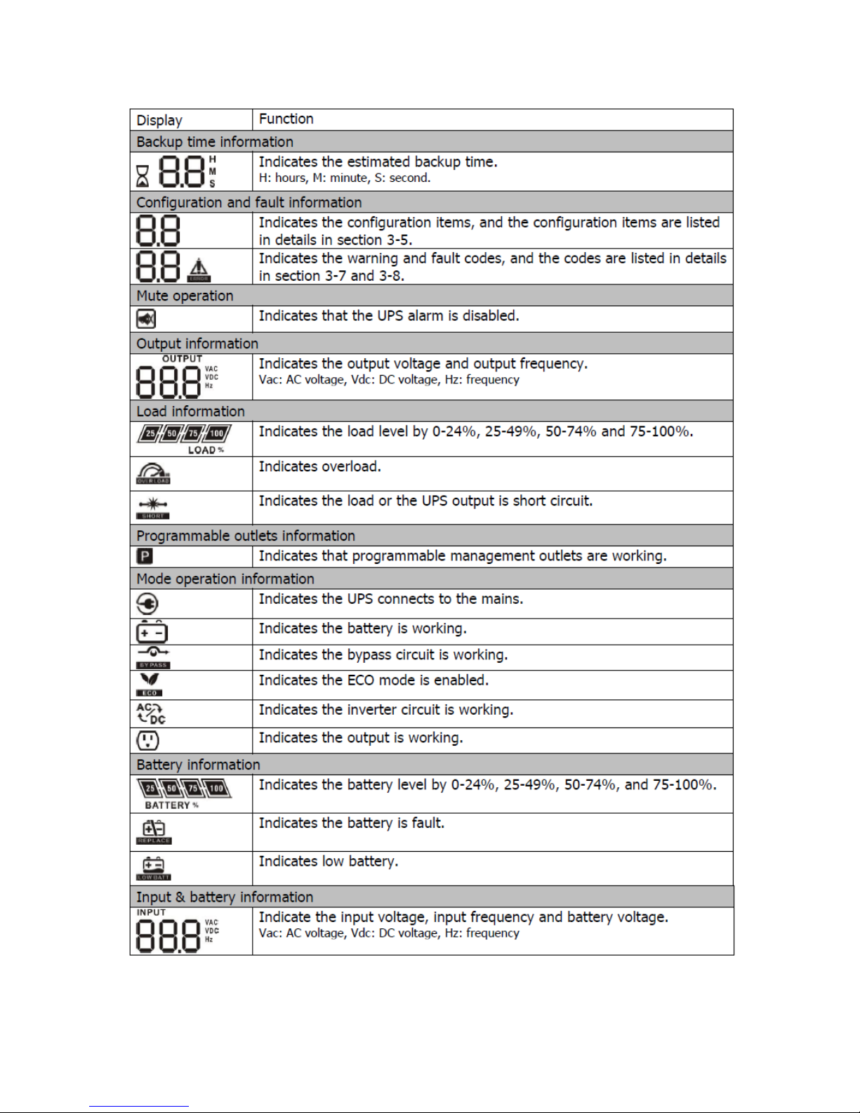
3.2.LCD Panel
Page 17
Page 18
3.3.Audible Alarm
Battery Mode
Sounding every 5 seconds
Low Battery
Sounding every 2 seconds
Overload
Sounding every second
Fault
Continuosly sounding
Bypass Mode
Sounding every 10 seconds
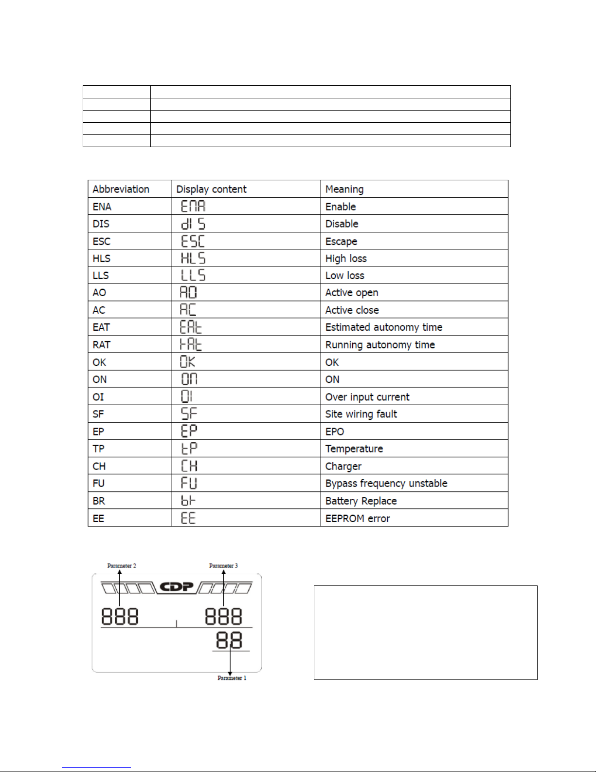
There are three parameters to set up the UPS.
Parameter 1: It´s for program alternatives.
Refer to below table.
Parameter 2 and parameter 3 are the setting
options or values for each program.
3.4.LCD Display wordings index
3.5.UPS Settings
Page 19
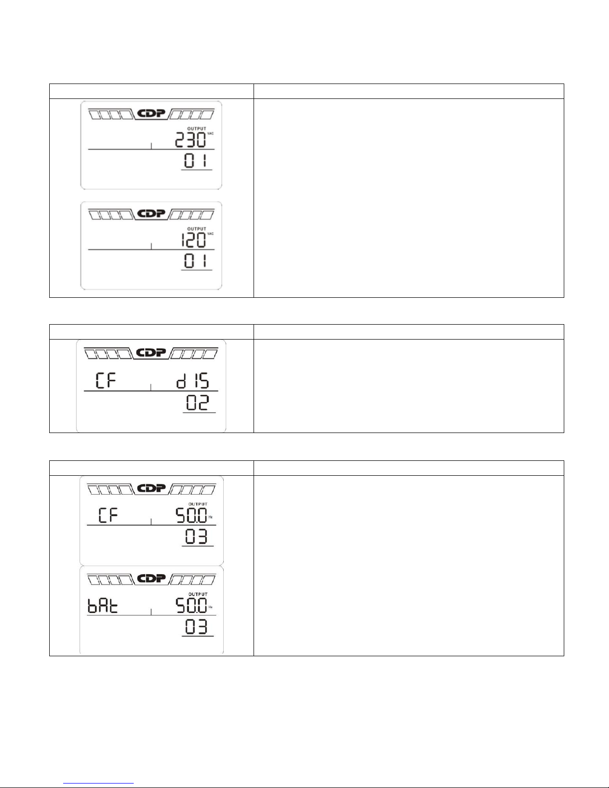
01: Output voltaje setting
Interface
Setting
Parameter 2: Output voltaje
For 200/208/220/230/240 VAC models, you may choose the
following output voltage:
200: presents output voltage is 200Vac
208: presents output voltage is 208Vac
220: presents output voltage is 220Vac
230: presents output voltage is 230Vac (Default)
240: presents output voltage is 240Vac
For 100/110/115/120/127 VAC models, you may choose the
following output voltage:
100: presents output voltage is 100Vac
110: presents output voltage is 110Vac
115: presents output voltage is 115Vac
120: presents output voltage is 120Vac (Default)
127: presents output voltage is 127Vac
Interface
Setting
Parameter 2: Enable or disable converter mode. You may
choose the following two options:
CF ENA: converter mode enable
CF DIS: converter mode disable (Default)
Interface
Setting
Parameter 2: Output frequency setting.
You may set the initial frequency on battery mode:
BAT 50: presents output frequency is 50Hz
BAT 60: presents output frequency is 60Hz
If converter mode is enabled, you may choose the following
output frequency:
CF 50: presents output frequency is 50Hz
CF 60: presents output frequency is 60Hz
02: Frequency Converter enable / disable
03: Output Frequency Setting
Page 20
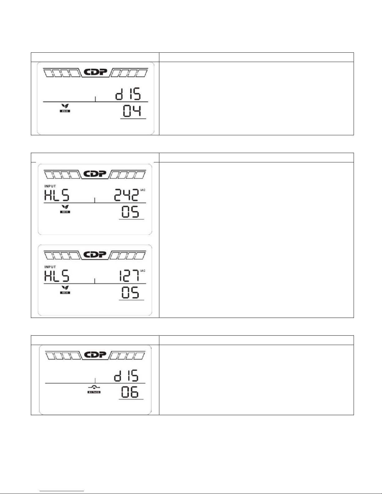
04: ECO enable/disable
Interface
Setting
Parameter 2: Enable or disable ECO function. You may
choose the following two options:
ENA: ECO mode enable
DIS: ECO mode disable (Default)
Interface
Setting
Parameter 2: Set the acceptable high voltage point and low
voltage point for ECO mode by pressing Down key or Up key.
HLS: High loss voltage in ECO mode in parameter 2.
For 200/208/220/230/240 VAC models, the setting range in
parameter 3 is from +7V to +24V of the nominal voltage.
(Default: +12V)
For 100/110/115/120/127 VAC models, the setting range in
parameter 3 is from +3V to +12V of the nominal voltage.
(Default: +6V)
LLS: Low loss voltage in ECO mode in parameter 2.
For 200/208/220/230/240 VAC models, the setting range in
parameter 3 is from -7V to -24V of the nominal voltage.
(Default: -12V)
For 100/110/115/120/127 VAC models, the setting voltage in
parameter 3 is from -3V to -12V of the nominal voltage.
(Default: -6V)
Interface
Setting
Parameter 2: Enable or disable Bypass function. You may
choose the following two options:
ENA: Bypass enable
DIS: Bypass disable (Default)
05: ECO voltaje range setting
06: Bypass enable/disable when UPS is off
Page 21
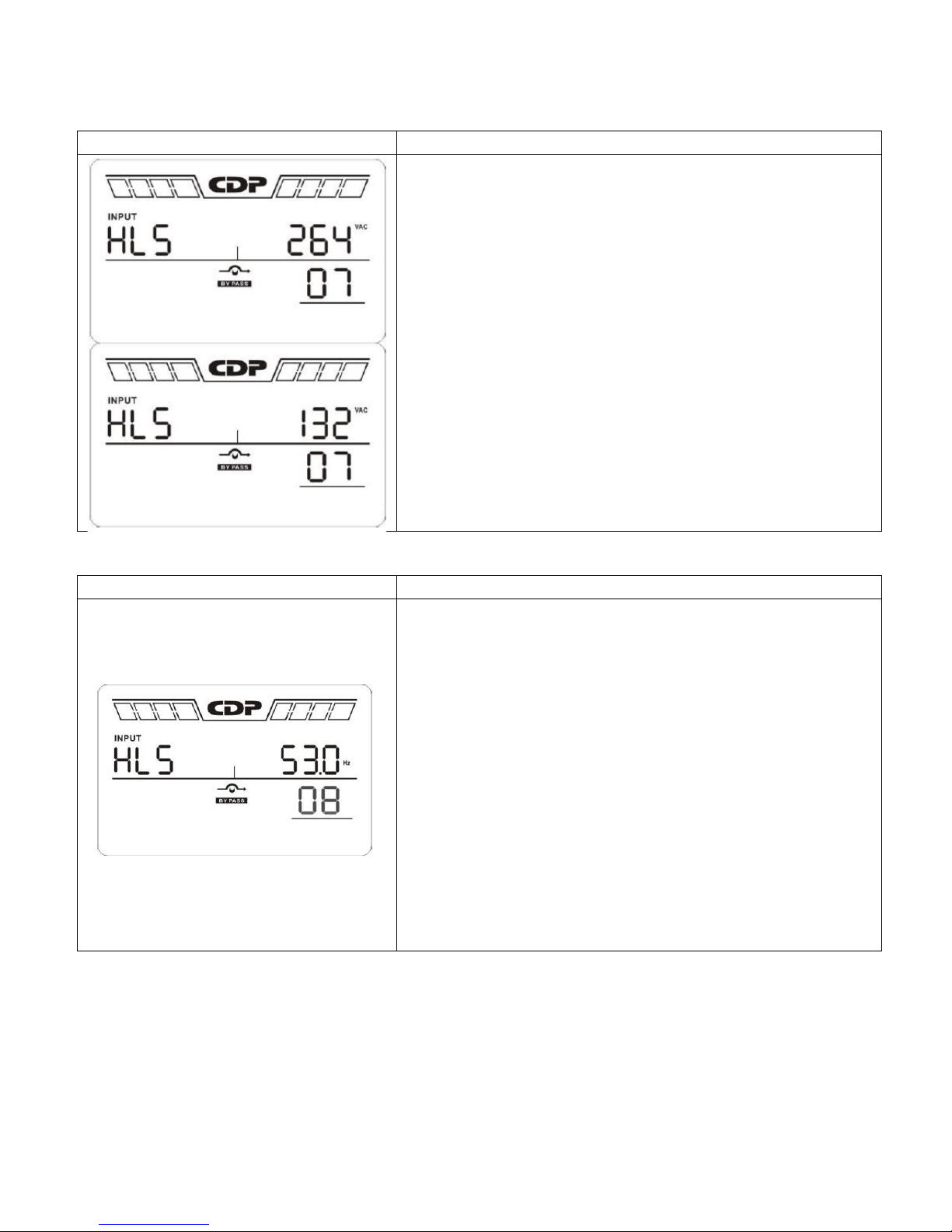
07: Bypass voltaje range setting
Interface
Setting
Parameter 2: Set the acceptable high voltage point and
acceptable low voltage point for Bypass mode by pressing the
Down key or Up key.
HLS: Bypass high voltage point
For 200/208/220/230/240 VAC models:
230-264: setting the high voltage point in parameter 3 from
230Vac to 264Vac. (Default: 264Vac)
For 100/110/115/120/127 VAC models:
120-140: setting the high voltage point in parameter 3 from
120Vac to 140Vac. (Default: 132Vac)
LLS: Bypass low voltage point
For 200/208/220/230/240 VAC models:
170-220: setting the low voltage point in parameter 3 from
170Vac to 220Vac. (Default: 170Vac)
For 100/110/115/120/127 VAC models:
85-115: setting the low voltage point in parameter 3 from
85Vac to 115Vac. (Default: 85Vac)
Interface
Setting
Parameter 2: Set the acceptable high frequency point and
acceptable low frequency point for Bypass mode by pressing
the Down key or Up key.
HLS: Bypass high frequency point
For 50Hz output frequency models:
51-55Hz: setting the frequency high loss point from 51Hz to
55HZ(Default: 53.0Hz)
For 60Hz output frequency models:
61-65Hz: setting the frequency high loss point from 61Hz to
65Hz(Default: 63.0Hz)
LLS: Bypass low Frequency point
For 50Hz output frequency models:
45-49Hz: setting the frequency low loss point from 45Hz to
49HZ(Default: 47.0Hz)
For 60Hz output frequency models:
55-59Hz: setting the frequency low loss point from 55Hz to
59Hz(Default: 57.0Hz)
08: Bypass frequency range setting
Page 22
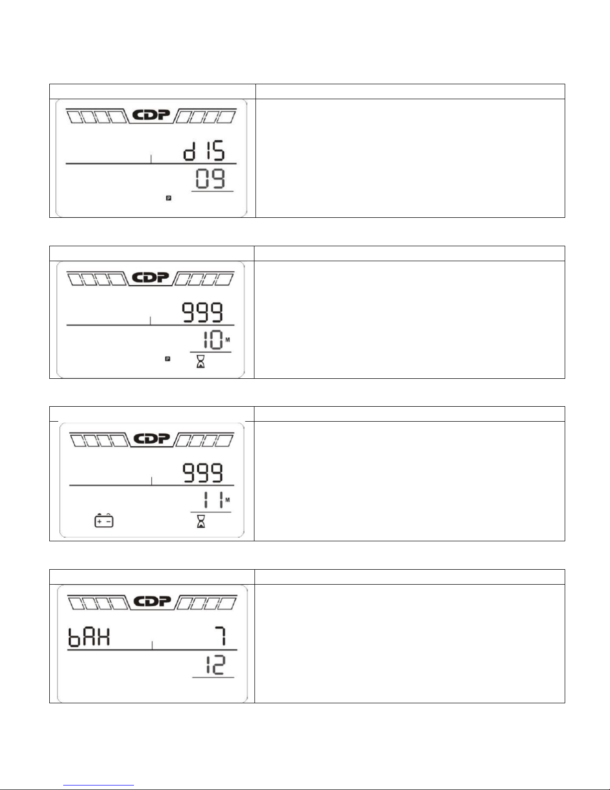
09: Programmable outlets enable/disable
Interface
Setting
Parameter 2: Enable or disable programmable outlets.
ENA: Programmable outlets enable
DIS: Programmable outlets disable (Default)
Interface
Setting
Parameter 2: Set up backup time limits for programmable
outlets.
0-999: setting the backup time limits in minutes from 0-999
for programmable outlets which connect to non-critical
devices on battery mode. (Default: 999)
Interface
Setting
Parameter 2: Set up backup time on battery mode for
general outlets.
0-999: setting the backup time in minutes from 0-999 for
general outlets on battery mode.
DIS: Disable the autonomy limitation and the backup time
will depend on battery capacity. (Default)
Note: When setting as “0”, the backup time will be only 10
seconds.
Interface
Setting
Parameter 2: Set up the battery total AH of the UPS.
7-999: setting the battery total capacity from 7-999 in AH.
Please set the correct battery total capacity if external battery
bank is connected.
10: Programmable outlets setting
11: Autonomy limitation setting
12: Battery total AH setting
Page 23
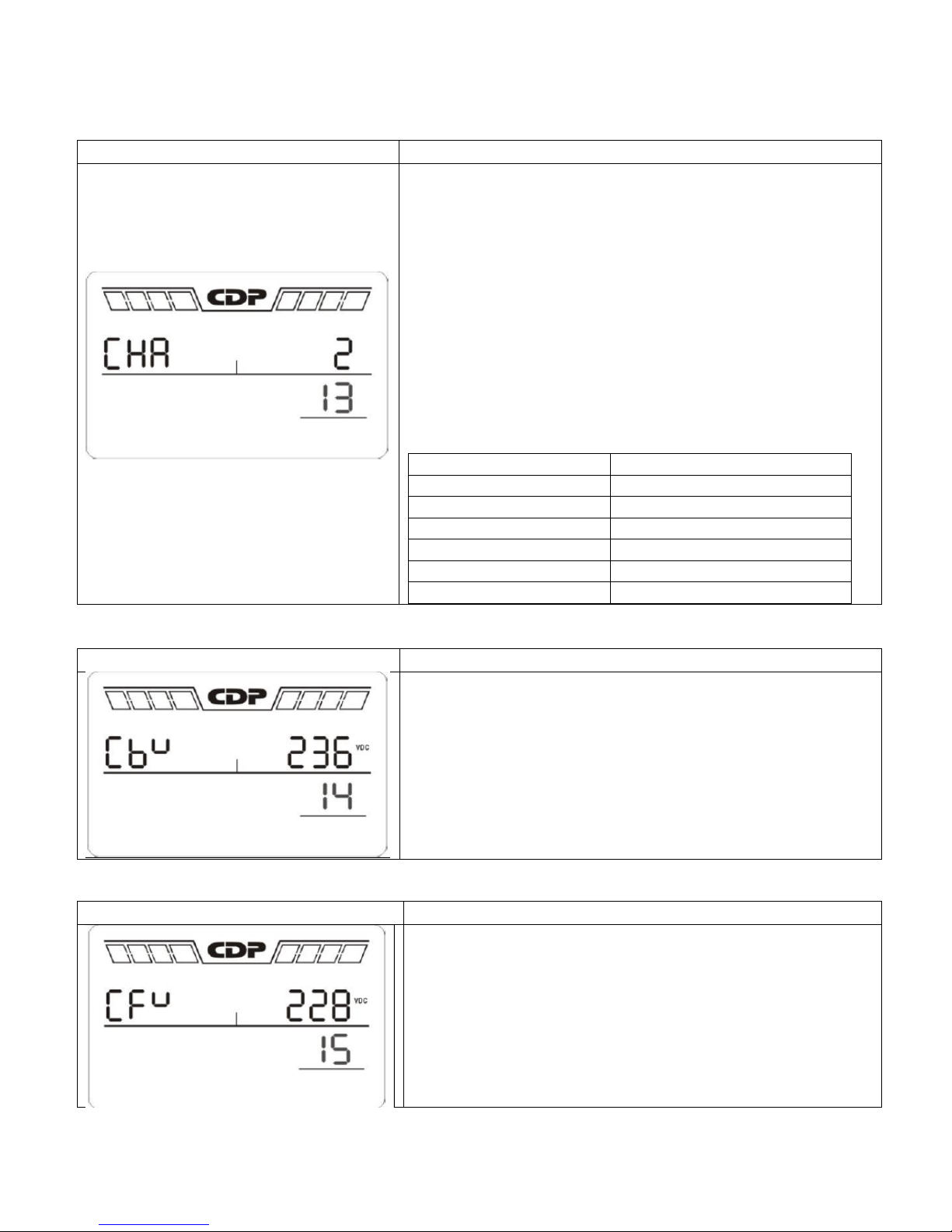
13: Maximum charger current setting
Interface
Setting
Parameter 2: Set up the charger maximum current.
For low voltage model with 24/36/48VDC
1/2/4/6/8: setting the charger maximum current 1/2/4/6/8
in Ampere. (Default: 2A)
For high voltage model with 24/36/48VDC
1/2/4/6/8/10/12: setting the charger maximum current
1/2/4/6/8/10/12 in Ampere. (Default: 2A)
For low voltage and high voltage model with 72/96VDC
1/2/4/6/8: setting the charger maximum current 1/2/4/6/8
in Ampere. (Default: 2A)
Note: Please set the appropriatecharger current based on
battery capacity used. The recommended charging current is
0.1C~0.3C of battery capacity as following table for
reference.
Battery capacity (AH)
Total charging current (A)
7-20
2
20-40
4
40-60
6
60-80
8
80-100
10
100-150
12
Interface
Setting
Parameter 2: Set up the charger boost voltage.
2.25-2.40: setting the charger boost voltage from 2.25
V/cell to 2.40V/cell. (Default: 2.36V/cell)
Interface
Setting
Parameter 2: Set up the charger float voltage.
2.20-2.33: setting the charger float voltage from 2.20
V/cell to 2.33V/cell. (Default: 2.28V/cell)
14: Charger boost voltaje setting
15: Charger float voltaje setting
Page 24
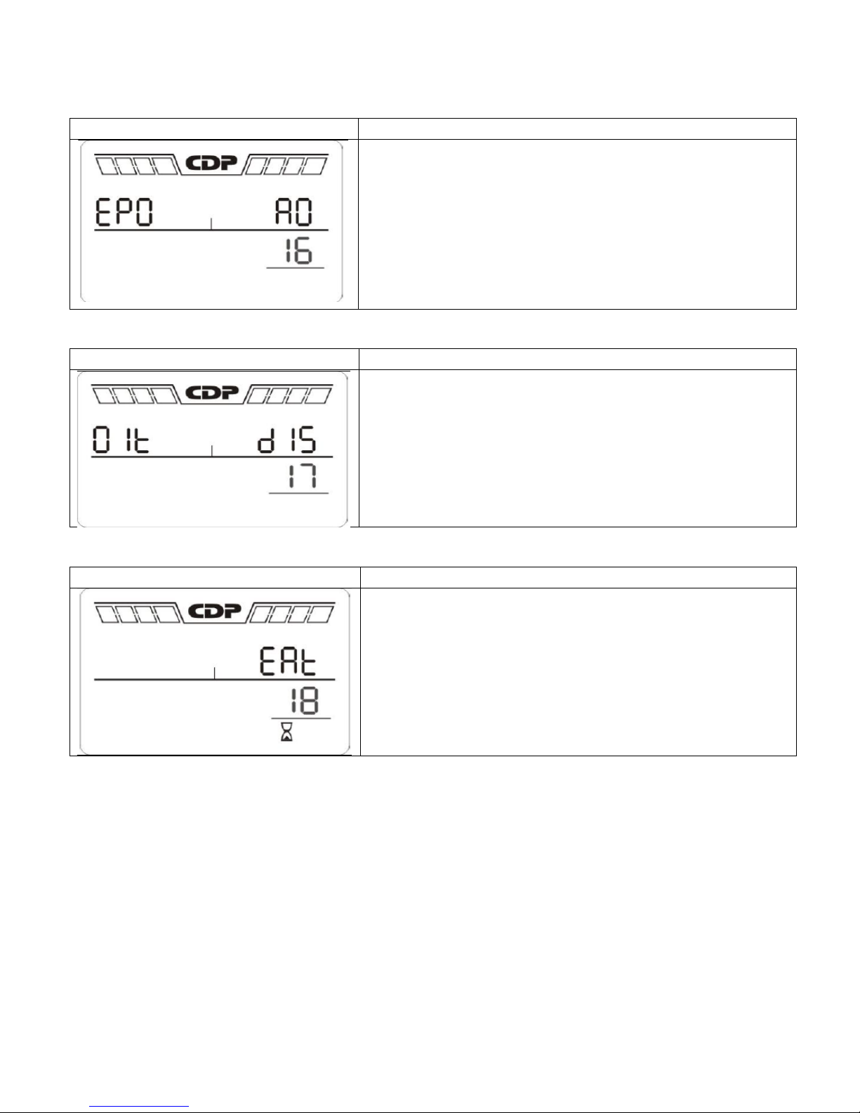
16: EPO Logic setting
Interface
Setting
Parameter 2: Set up the EPO function control logic.
AO: Active Open (Default). When AO is selected as EPO
logic, it will activate EPO function with Pin 1 and Pin 2 in
open status.
AC: Active Close. When AC is selected as EPO logic, it will
activate EPO function with Pin 1 and Pin 2 in close status.
Interface
Setting
Parameter 2: Allow or disallow external output isolation
transformer connection.
ENA: If selected, it’s allowed to connect to an external
output isolation transformer.
DIS: If selected, it’s not allowed to connect to external
output isolation transformer. (Default)
Interface
Setting
Parameter 2: Set up the display setting for autonomy time
EAT: If EAT is selected, it will display the remaining
autonomy time. (Default)
RAT: If RAT is selected, it will show accumulated autonomy
time so far.
17: External output isolation transformer connection
18: Display setting for autonomytime
Page 25
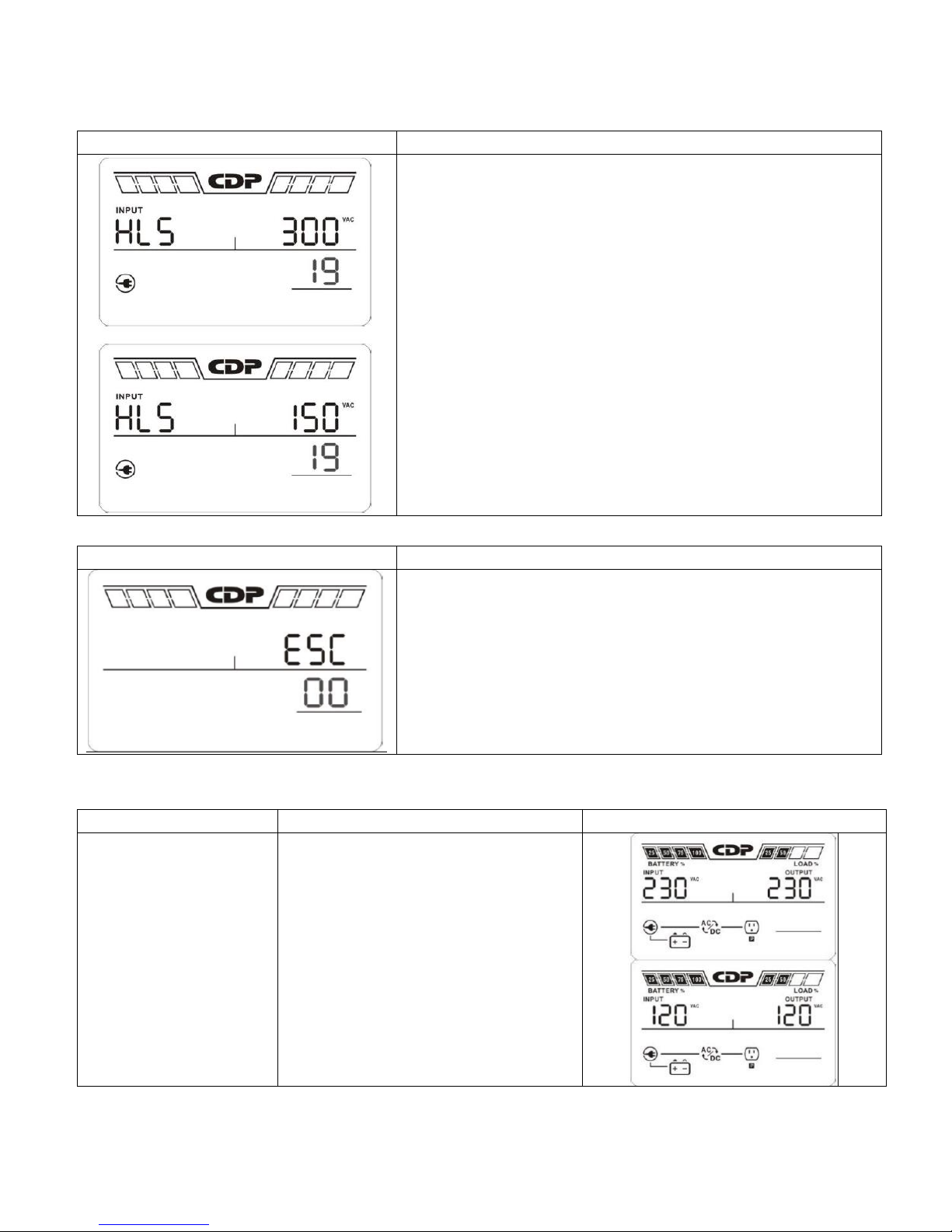
19: Acceptable input voltaje range setting
Interface
Setting
Parameter 2: Set the acceptable high voltage point and
acceptable low voltage point for input voltage range by
pressing the Down key or Up key.
HLS: Input high voltage point
For 200/208/220/230/240 VAC models:
280/290/300: setting the high voltage point in parameter
2. (Default: 300Vac)
For 100/110/115/120/127 VAC models:
140/145/152: setting the high voltage point in parameter
2. (Default: 150Vac)
LLS: Bypass low voltage point
For 200/208/220/230/240 VAC models:
110/120/130/140/150/160: setting the low voltage
point in parameter 2. (Default: 110Vac)
For 100/110/115/120/127 VAC models:
50/60/65/70/75/80: setting the low voltage point in
parameter 2.(Default: 55Vac)
Interface
Setting
Exit the setting mode.
Operating Mode
Description
LCD Display
Online mode
When the input voltage is within
acceptable range, UPS will provide
pure and stable AC power to output.
The UPS will also charge the battery
at online mode.
00: Exit setting
3.6.Operating Mode Description
Page 26
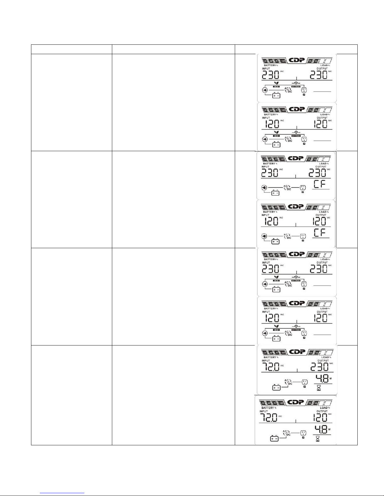
Operating Mode
Description
LCD Display
ECO mode
Energy saving mode:
When the input voltaje is whitin
voltaje regulation range, UPS will
bypass voltaje to output for energy
saving. The UPS will also charge the
battery at ECO mode.
Frequency Converter
mode
When input frequency is within 40Hz
to 70Hz, the UPS can be set at
constant output frequency, 50Hz or
60Hz. The UPS will still charge
battery under this mode.
Battery mode
Energy saving mode:
When the input voltaje is whitin
voltaje regulation range, UPS will
bypass voltaje to output for energy
saving. The UPS will also charge the
battery at ECO mode.
Frequency Converter
mode
When the input voltaje is beyond the
aceptable range or power failure, the
UPS will backup power from battery
and alar mis sounding every 5
seconds.
Page 27
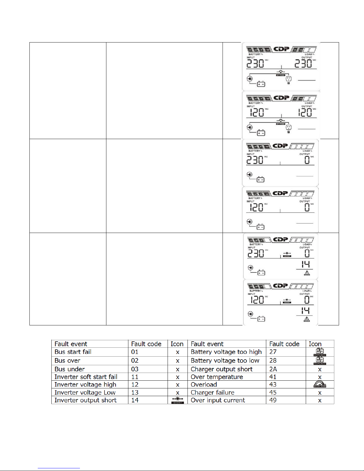
Bypass mode
When input voltaje is within
aceptable range but UPS is overload,
UPS will enter bypass mode or bypass
mode can be set by front panel. Alar
mis sounding every 10 seconds
Standby mode
UPS is powered off and no output
supply power, but still can charge
batteries.
Fault mode
When a fault has occurred, the
ERROR icon and the fault code will be
displayed.
3.7.Faults Reference Code
Page 28
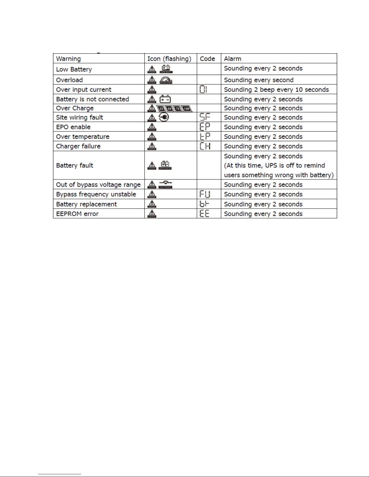
3.8.Warning indicator
NOTE: “Site Wiring Fault” function can be enabled / disabled via software. Please
check software manual for details.
Page 29
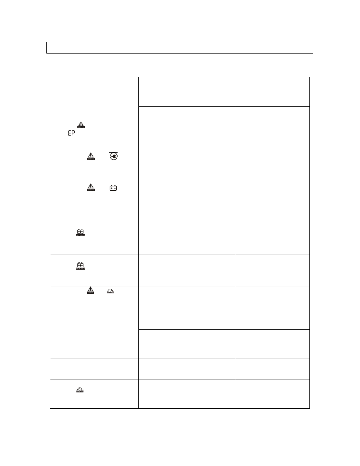
4.Troubleshooting
Symptom
Possible Cause
Remedy
No indication and alarm even
though the mains is normal.
The AC input power is not
connected well.
Check if input power cord
firmly connected to the
mains.
The AC input is connected to the
UPS output.
Plug AC input power cord
to AC input correctly.
The icon and the warning
code flash on LCD display.
Alarm is sounding every 2
seconds.
EPO function is activated.
Set the circuit in closed
position to disable EPO
function.
The icons of and flash
on LCD display and alarm is
sounding every 2 seconds.
Line and neutral conductors of
UPS input are reversed.
Rotate mains power
socket by 180° and then
connect to UPS system.
The icons of and
flashes on LCD display and
alarm is sounding every 2
seconds.
The external or internal battery is
incorrectly connected.
Check if all batteries are
connected well.
Fault code is shown as 27 and
the icon is lighting on LCD
display. Alarm is continuously
sounding.
Battery voltage is too high or the
charger is fault.
Contact your dealer.
Fault code is shown as 28 and
the icon is lighting on LCD
display. Alarm is continuously
sounding.
Battery voltage is too low or the
charger is fault.
Contact your dealer.
The icons of and flash on
LCD display and alarm is
sounding every second.
UPS is overload
Remove excess loads
from UPS output.
UPS is overloaded. Devices
connected to the UPS are fed
directly by the electrical network
via the Bypass.
Remove excess loads
from UPS output.
After repetitive overloads, the UPS
is locked in the Bypass mode.
Connected devices are fed directly
by the mains.
Remove excess loads
from UPS output first.
Then shut down the UPS
and restart it.
Fault code is shown as 49 on
LCD display and alarm is
continuously sounding.
UPS is overinput current.
Remove excess loads
from UPS output.
Fault code is shown as 43 and
the icon is lighting on LCD
display. Alarm is continuously
sounding.
The UPS shut down automatically
because of overload at the UPS
output.
Remove excess loads
from UPS output and
restart it.
If the UPS system does not opérate correctly, please solve the problema by using the
table below:
Page 30
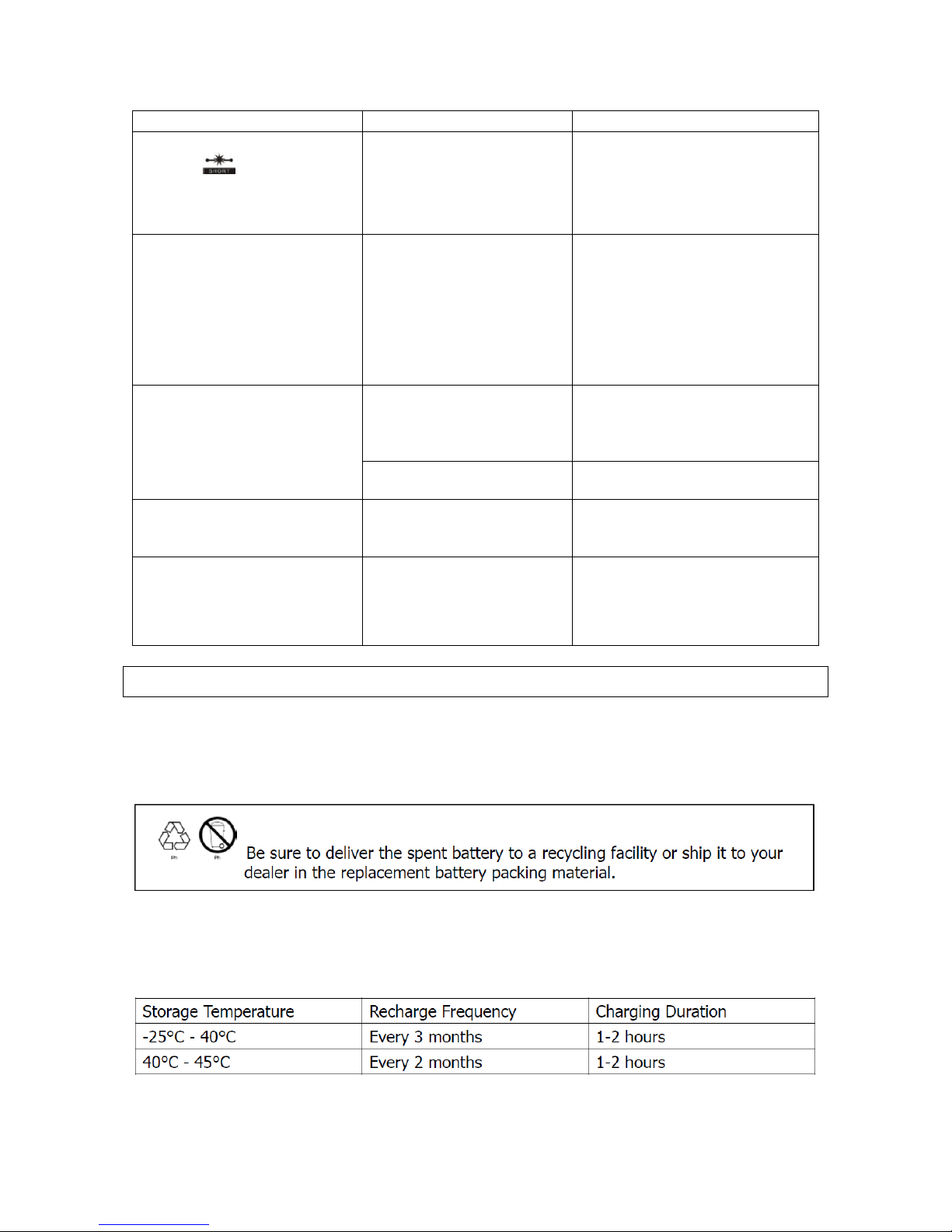
Symptom
Possible Cause
Remedy
Fault code is shown as 14 and
the icon is lighting on
LCD display. Alarm is
continuously sounding.
The UPS shut down
automatically because short
circuit occurs on the UPS
output.
Check output wiring and if
connected devices are in short
circuit status.
Fault code is shown as 01, 02,
03, 11, 12, 13 and 41 on LCD
display and alarm is
continuously sounding.
A UPS internal fault has
occurred. There are two
possible results:
1. The load is still supplied,
but directly from AC power
via bypass.
2. The load is no longer
supplied by power.
Contact your dealer
Battery backup time is shorter
than nominal value.
Batteries are notfully
charged
Charge the batteries for at least
5 hours and then check capacity.
If the problem still persists,
consult your dealer.
Batteries defect
Contact your dealer to replace
the battery.
Fault code is shown as 2 A on
LCD display and alarm is
continuously sounding.
The short circuit occurs on
the chargeroutput.
Check if batterywiring of
connected external pack is in
short circuit status.
Fault code is shown as 45 on
LCD display. At the same time,
alarm is continuously
sounding.
The charger doesnot have
output and battery
voltageis less than 10V/PC.
Contact your dealer.
5.Storage and Maintenance
Operation
The UPS system contains no user-serviceable parts. If the battery service life (3 to 5 years
at 25°C ambient temperatur) has been exceded, the batteries must be replaced. In this
case, please contact your dealer.
Storage
Before storing, charge the UPS 5 hours. Store the UPS covered and upright in a cool, dry
location. During storage, recharge the battery in accordance with the following table:
Page 31

6.Specifications – Tower Models
MODEL
UPO 11-1(AX)
UPO 11-1.5(AX)
UPO 11-2(AX)
UPO 11-3(AX)
CAPACITY*
1000VA/1000W
1500VA/1500W
2000VA/2000W
3000VA / 3000W
INPUT
Voltage
Range
Low Line
Transfer
80VAC/70VAC/60VAC/55VAC ± 5 %
(based on load percentage 100% - 80 % / 80 % - 70 % / 70 - 60 % / 60 % - 0)
Low Line
Comeback
87VAC/77VAC/67VAC/52VAC ± 5 %
High Line
Transfer
152 VAC ± 5 %
High Line
Comeback
145 VAC ± 5 %
Frequency Range
40Hz ~ 70 Hz
Phase
Single phase with ground
Power Factor
≧ 0.99 @ full load
THDi
≦ 5% @ 100~130VAC THDU < 1.6% @ input and full linear load condition
OUTPUT
Output voltage
100*/110*/115*/120/127 VAC
AC Voltage Regulation
± 1% (Batt. Mode)
Frequency Range
(Synchronized Range)
47 ~ 53 Hz or 57 ~ 63 Hz
Frequency Range
50 Hz ± 0.1 Hz or 60Hz ± 0.1 Hz (Batt. Mode)
Current Crest Ratio
3:01
Harmonic Distortion
≦ 2 % THD (Linear Load) ; 4 % THD (Non-linear Load)
Transfer
Time
AC Mode to
Batt. Mode
Zero
Inverter to
Bypass
< 4 ms
Waveform (Batt. Mode)
Pure Sinewave
EFFICIENCY
AC Mode
≧90% @ full charged battery
≧91% @ full charged battery
ECO Mode
≧98% @ full charged Battery
Battery Mode
≧88%
≧90%
BATTERY
Battery Type
12V/7AH
12V/9AH
12V/7AH
12V/9AH
Numbers 3 3 6 6
Recharge Time
3 hours recover to 95% capacity for internal battery@ 2A charging current, Discharge FV
time at 25° C / 10,20V
Charging Current
Default 2A, max. 16A adjustable opcional
Charging Voltage
41.0 VDC ± 1%
41.0 VDC ± 1%
82.1 VDC ±1%
82.1 VDC ±1%
PHYSICAL
Dimension, DxWxH (mm)
397 X 145 X 220
421 X 190 X 318
Net
Weight
With battery
13.0kg
14.6kg
23.2kg
28.0kg
Without battery
6.6kg
7kg
9.9kg
12.3kg
ENVIRONMENT
Operation Humidity
20-95 % RH @ 0- 40°C (non-condensing) / -45°C to 74°C without Batteries
Noise Level
Less than 50dBA @ 1 Meter (With fan speed control)
MANAGEMENT
Smart RS-232 or USB
Supports Windows® 2000/2003/XP/Vista/2008/7/8/10, Linux, Unix and MAC
Page 32

Optional SNMP / Dry
Contacts
Power management from SNMP manager and web browser / CDP AS400 Card
* Derate capacity to 80% of capacity in Frequency converter mode and to 80% when the output
voltage is adjusted to 100VAC.
** Product specifications are subject to change without further notice.
 Loading...