

Page 1
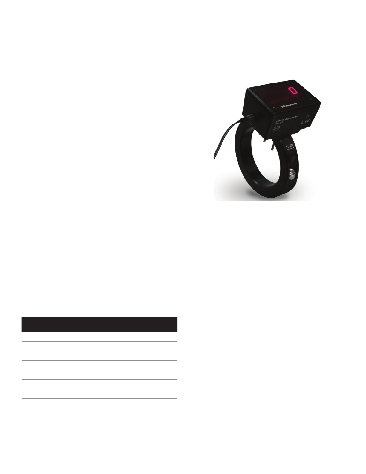
CDI 5400
FLOWMETER FOR COMPRESSED-AIR SYSTEMS - Rev. 3
• Easy to install
• Display rotates to facilitate use on horizontal
or vertical pipes
• No moving parts
• Weather resistant and surge protected
• Milliamp output
• Pulse output convertible to threshold output
• User-congurable scaling, ltering and units
of measure
• Optional wired and wireless outputs for networking
The CDI 5400 clamps onto a pipe, with two ow-sensing probes
projecting into the pipe through 3/16-in. drilled holes. It seals
directly to the pipe; no cutting or welding is required for installation. Because each owmeter is made and calibrated for a
specic size of pipe, the digital display indicates ow directly,
with no setup or adjustment.
The meter measures ow by maintaining one probe warmer
than the other. It determines the mass ow rate from the amount
of heat required. The ow rate, in scfm or equivalent units, is
shown on a large, four-digit display; a 4-20 mA output and a
pulse output permit remote dis-play, totalizing and data collection.
AVAILABLE SIZES
Nominal
a
Size
2 in. 600 5400-20S 5400-20C
2.5 in. 800 5400-25S 5400-25C
3 in. 1200 5400-30S 5400-30C
4 in. 2000 5400-40S 5400-40C
5 in. 2500 5400-50S —
6 in. 5000 5400-60S —
8 in 6000 5400-80S —
(a) Other sizes are available. Please contact CDI. For metering larger
pipe sizes, please see our 5400 Series owmeters.
(b) Range of milliamp output and recommended maximum ow. Flowmeters
for copper pipe have smaller ranges. Meters will function at somewhat
higher ow rates but at reduced accuracy.
Range
(scfm)
b
Model No. for
Sch 40 Steel
Model No. for
Type L Copper
b
SPECIFICATIONS
Accuracy
5 percent of reading plus 1 percent of range for ows from
10 percent to 100 percent of indicated range at air temperatures between 20 and 120 degrees Fahrenheit
Fluids
Compressed Air, Nitrogen
Operating Pressure
200 psig maximum on Sch. 40 steel and on Type L Copper;
consult CDI for other materials and higher pressures.
Input Power
250 mA at 24 Vdc
Output resistance
600 Ohms max.
Exposed Materials
Stainless steel, gold, thermal epoxy and Viton (seal)
Display
Four-digit LED display
Response time
One second to 63 percent of change in value at ows above
30 percent of range
US Patent 6,802,217
CDI METERS, INC. 10/24/2016
Find Quality Products Online at: [email protected]
Specications are subject to change without notice.
© CDI Meters, Inc. 2016
www.GlobalTestSupply.com
Page 2

APPLICATION
The meter is designed for use with compressed air and nitrogen. If the meter will be used at pressures below 15 psig,
consult CDI about velocity limitations. The air must be free of oil,
dirt that could foul the probes, and suspended water droplets. In
a compressed-air application, the meter should be installed
downstream of a dryer. Each meter is calibrated for a specic
size and type of pipe. If a meter will be used in a type or size of
pipe that is not listed, consult CDI about a special calibration.
The meter is not to be used in safety or life-support applications. It should not be used as a sole means of determining
required capacity of air compressors and related equipment.
The meter must not be used in hazardous locations.
INSTALLATION
Drilling the holes to install the meter will release some metal
shavings into the pipe. When planning the installation, make sure
that all downstream equipment is protected by lters, or take
other precautions to ensure that shavings do not reach critical
equipment or get blown out in a way that could cause injury.
For best accuracy, the meter should be installed with at least
20 diameters of straight pipe upstream and three diameters
downstream. Avoid installing the meter down-stream of any
item that could distort or concentrate the ow, such as a
partially-closed valve, a regulator, a lter or moisture separator, two closely-spaced elbows in different planes, a
long-radius elbow or a curved hose. Allow at least 30 diameters of straight pipe between any such item and the meter. If
a valve or other restriction will be immediately downstream of
the meter, provide at least ve diameters downstream. Select
a location that meets these requirements and also provides
good visibility from the plant oor. If this is not possible,
consider using the remote display discussed below.
To install the meter, rst shut off the supply of air to the pipe
where the meter will be mounted and allow the pres-sure to
bleed down. Clamp the drill guide rmly to the pipe, orienting
it for best visibility of the meter. Drill the two holes and remove
any resulting burrs from the outside of the pipe. Make sure
the outside surface of the pipe is clean and smooth.
Before mounting the meter on the pipe, orient the display
relative to the ring for best visibility. The display and cover can
be removed and rotated 180 degrees relative to the meter
housing, and the meter housing can be rotated 90 degrees
relative to the ring, using screws behind the housing.
Next remove the back half of the ring, insert the probes into
the holes in the pipe with the ow arrow pointing in the proper
direction, and re-assemble the rings. Tighten the cap screws
rmly and evenly so that the gaps between the halves of the
rings are about equal on both sides of the pipe.
MILLIAMP AND PULSE OUTPUTS
The meter has an isolated, unpowered, milliamp output. The
meter is shipped with a jumper in place to power the output
from the instrument’s dc supply. With the jumper in place, the
meter will source a dc signal. The pulse output is an open
collector, referenced to the instrument ground. For applications in which a contact-closure output is required, the
isolated pulse output (CDI 5200-IPO) should be used. It
installs inside the meter. The pulse output can be made into a
threshold output by using the optional conguration cable.
DISPLAY CONTROL AND CONFIGURATION
The display can be cycled through rate, daily usage and cumulative usage using a button indicated by a circle on the front of
the meter. The same button can be used to select a default
display option, reset totals and select units of measure. Please
refer to the conguration instructions enclosed with the meter.
METER CONFIGURATION
Several parameters of the meter’s conguration can be
changed by the user using an optional conguration cable
and software available from CDI. These parameters include
milliamp scaling, pulse scaling, conversion from pulse out-put
to threshold output, ltering (smoothing) of the output, pipe
inside diameter, and pressure compensation for high-pressure applications. For most applications, none of these
parameters need to be changed.
POWER SUPPLY
Each meter is furnished with a wall-plug dc supply for 110 V to
230 Volt AC main with a 6-foot (1.5 M) cable plus a 14-foot (4.2
M) extension cable. Prongs for Australian, European, UK and US
outlets are provided, as appropriate. The meter may alternatively
be hard wired to a 24-Volt dc sup-ply. Eighteen-Volt supplies
furnished with some earlier CDI owmeters must not be used.
DRILL GUIDE
For pipe sizes three inches and larger, the drill guides are
half rings that bolt to the back halves of the meter rings (CDI
5400-XX-DG). For the two- and 2-1/2 inch sizes, a single drill
guide is used (CDI 5400-S-DG). There is also a universal drill
guide (CDI 5400-U-DG) for all 5400 sizes. Each of the drill
guides is furnished with a 3/16 inch drill bit and a hex wrench.
Please note that the 5200-DG drill guide cannot be used with
the 5400-series owmeters.
LIMITED WARRANTY
CDI warrants solely to the buyer that the Model 5400 Flowmeter
shall be free from defects in materials and workmanship, when
given normal, proper and intended usage, for three years from
the date of purchase. During the warranty period, CDI will repair
or replace (at its option) any defective product at no cost to the
buyer. The foregoing warranty is in lieu of any other warranty,
express or implied, written or oral (including any warranty of
merchantability or tness for a particular purpose). CDI’s liability
arising out of the manufacture, sale or supplying of the owmeter, whether based on warranty, contract, tort or otherwise, shall
not exceed the actual purchase price paid by the buyer, and in
no event shall CDI be liable to anyone for special, incidental or
consequential damages.
CDI METERS, INC. 06/13/2016
Find Quality Products Online at: [email protected]
Specications are subject to change without notice.
© CDI Meters, Inc. 2016
www.GlobalTestSupply.com
 Loading...