

CDIL MBR 10100 Datasheet
MBR1060, MBR1080,
MBR1090, MBR10100
MBR1060 and MBR10100 are Preferred Devices
SWITCHMODE
Power Rectifiers
. . . using the Schottky Barrier principle with a platinum barrier
metal. These state–of–the–art devices have the following features:
• Guard–Ring for Stress Protection
• Low Forward Voltage
• 150°C Operating Junction Temperature
• Epoxy Meets UL94, VO at 1/8″
• Low Power Loss/High Efficiency
• High Surge Capacity
• Low Stored Charge Majority Carrier Conduction
Mechanical Characteristics:
• Case: Epoxy, Molded
• Weight: 1.9 grams (approximately)
• Finish: All External Surfaces Corrosion Resistant and Terminal
Leads are Readily Solderable
• Lead Temperature for Soldering Purposes:
260°C Max. for 10 Seconds
• Shipped 50 units per plastic tube
• Marking: B1060, B1080, B1090, B10100
MAXIMUM RATINGS
Please See the Table on the Following Page
http://onsemi.com
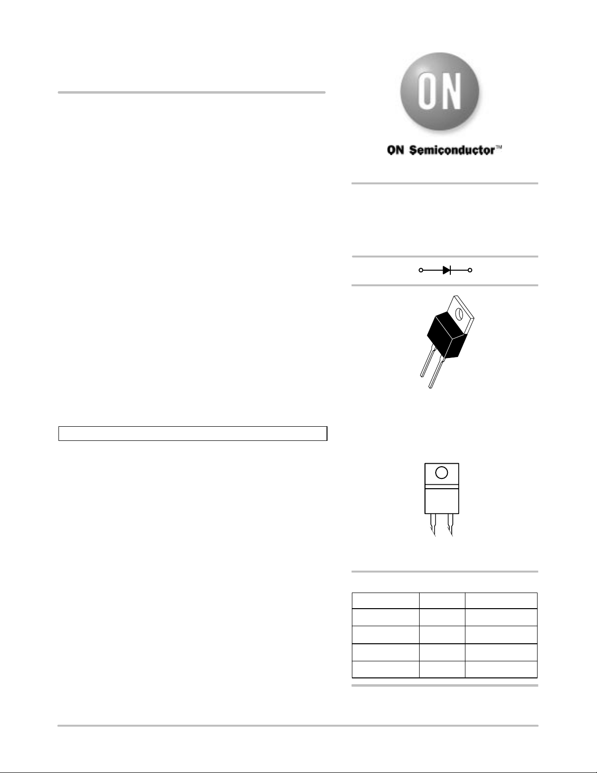
SCHOTTKY BARRIER
RECTIFIERS
10 AMPERES
60 to 100 VOLTS
3 1, 4
4
1
3
TO–220AC
CASE 221B
PLASTIC
Semiconductor Components Industries, LLC, 2000
October, 2000 – Rev. 3
MARKING DIAGRAM
B10x0
B10x0 = Device Code
x = 6, 8, 9 or 10
ORDERING INFORMATION
Device Package Shipping
MBR1060 TO–220
MBR1080 TO–220 50 Units/Rail
MBR1090 TO–220 50 Units/Rail
MBR10100 TO–220 50 Units/Rail
Preferred devices are recommended choices for future use
and best overall value.
1 Publication Order Number:
50 Units/Rail
MBR1060/D

MBR1060, MBR1080, MBR1090, MBR10100
MAXIMUM RATINGS
Rating Symbol
Peak Repetitive Reverse Voltage
Working Peak Reverse Voltage
DC Blocking Voltage
Average Rectified Forward Current (Rated VR) TC = 133°C I
Peak Repetitive Forward Current
(Rated V
, Square Wave, 20 kHz) TC = 133°C
R
Nonrepetitive Peak Surge Current
V
V
F(AV)
I
I
RRM
RWM
V
FRM
FSM
1060 1080 1090 10100
60 80 90 100 Volts
R
(Surge applied at rated load conditions halfwave, single phase, 60 Hz)
Peak Repetitive Reverse Surge Current (2.0 µs, 1.0 kHz) I
Operating Junction Temperature T
Storage Temperature T
RRM
J
stg
Voltage Rate of Change (Rated VR) dv/dt 10,000 V/µs
THERMAL CHARACTERISTICS
Maximum Thermal Resistance — Junction to Case
— Junction to Ambient
R
θ
JC
R
θ
JA
ELECTRICAL CHARACTERISTICS
Maximum Instantaneous Forward Voltage (Note 1.)
(i
= 10 Amps, TC = 125°C)
F
= 10 Amps, TC = 25°C)
(i
F
(i
= 20 Amps, TC = 125°C)
F
(i
= 20 Amps, TC = 25°C)
F
Maximum Instantaneous Reverse Current (Note 1.)
(Rated dc Voltage, T
(Rated dc Voltage, T
= 125°C)
C
= 25°C)
C
1. Pulse Test: Pulse Width = 300 µs, Duty Cycle ≤2.0%.
v
F
i
R
MBR
10 Amps
20 Amps
150 Amps
0.5 Amp
65 to +150 °C
65 to +175 °C
2.0
60
0.7
0.8
0.85
0.95
6.0
0.10
Unit
°C/W
Volts
mA
http://onsemi.com
2
 Loading...