

Page 1
USER’S MANUAL
Rev. 03/2009
00003
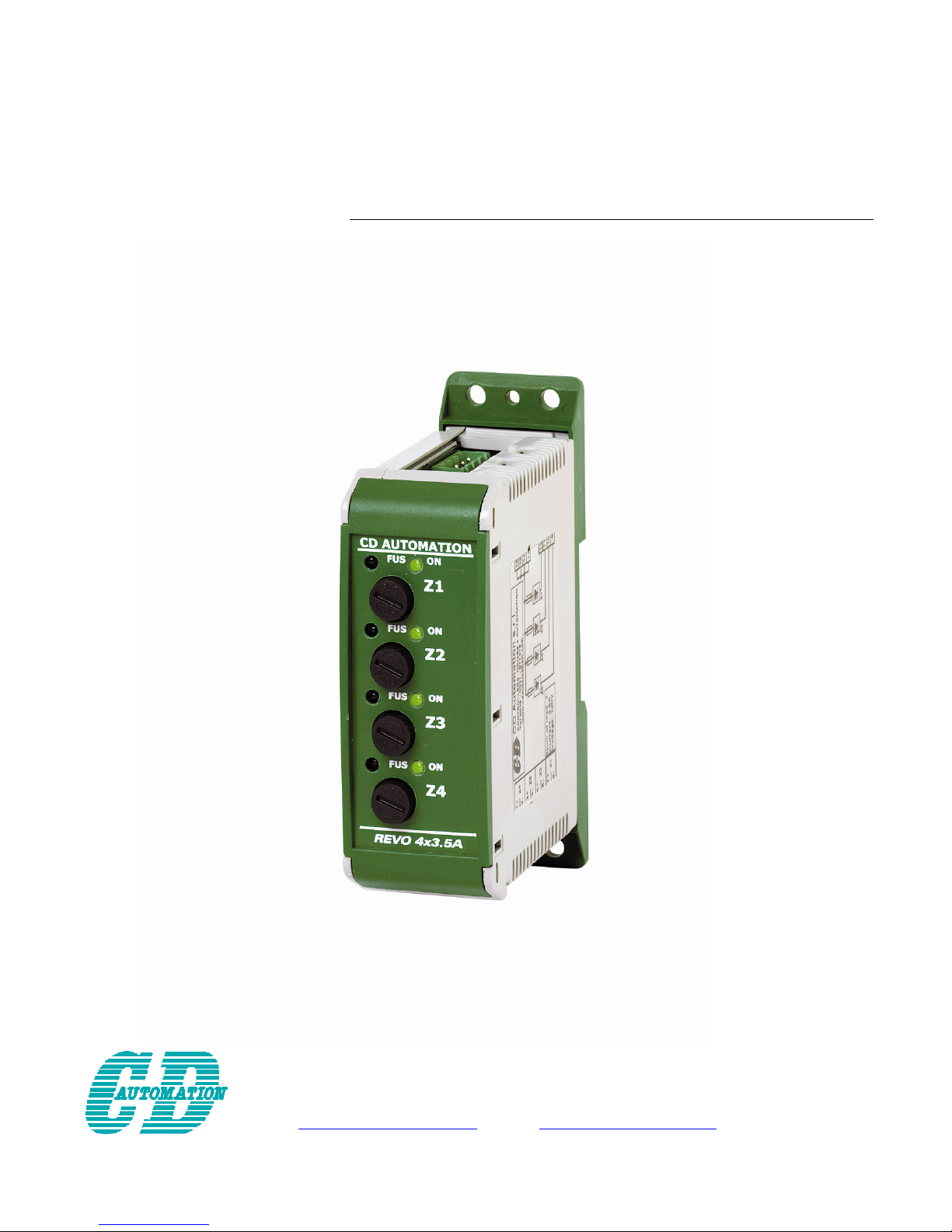
Revo Sx
Solid-State Relay
4x3,5A – 3x4,5A – 2x7A
CD Automation S.r.l.
Via Picasso 34/36 - 20025 – Legnano (MI) – ITALY
Tel +39 0331 577479 – Fax +39 0331 579479
E-Mail: [email protected] - WEB: www.cdautomation.com
Page 2
CD Automation srl REVO 4x3,5A User’s manual
Important warning for safety
Thyristor units are used in power industrial equipment.
The voltages used in the Thyristor unit can cause severe electrical shock, and could be lethal.
Don't remove the plastic cover.
Don't use this unit in aerospace and nuclear application.
Electric Shock Hazard (Risque the choque électrique)
When thyristor unit has been connected to main supply voltage and is switched off, before to touch it be
secure that the unit is isolated and wait at least one minute to allow discharging internal capacitors. Thus
be secure that:
• Access to thyristor unit is only permitted to specialized personnel;
• The authorized personnel must read this manual before to have access to the unit;
• The access to the unit must be denied to unauthorized personnel.
Important warnings(attention)
Local regulations regarding electrical installation should be rigidly observed.
• Safety regulations must be rigidly observed.
• Don't bend components to maintain insulation distances.
• Protect the unit from high temperature humidity and vibrations.
• Don't touch components to prevent electrostatic discharges on them.
• Verify that all rating is in line with real needs.
• If authorized personnel must measure voltage current etc. on units, take away rings and other jewels
from fingers and hands.
• Authorized personnel working on thyristor unit under power supply voltage must work on insulated
board. Be secure that board is not connected to earth.
This listing does not represent a complete enumeration of all necessary safety cautions.
Protection(protection)
The thyristor unit has a polymeric plastic cover to compliance to International specification IP20.
To understand if IP20 protection is sufficient should be evaluated the installation place.
Open Type Equipment.
Electromagnetic compatibility (compatibilité électromagnétique)
Our thyristor units have an excellent immunity to electromagnetic interferences if all suggestions
contained in this manual are respected. In respect to a good Engineering practice, all inductive loads like
solenoids contactor coils should have a filter in parallel.
Emissions (Emission, Emissioni)
All solid-state power controllers emit a certain amount of radio-frequency energy because of the fast
switching of the power devices.
The CD Automation’s Thyristor unit are in accord with the EMC norms, CE mark.
In most installations, near by electronic systems will experience no difficulty with interference. If very
sensitive electronic measuring equipment or low-frequency radio receivers are to be used near the unit,
some special precautions may be required. These may include the installation of a line supply filter and
the use of screened (shielded) output cable to the load.
Page 3
CD Automation srl REVO 4x3,5A User’s manual
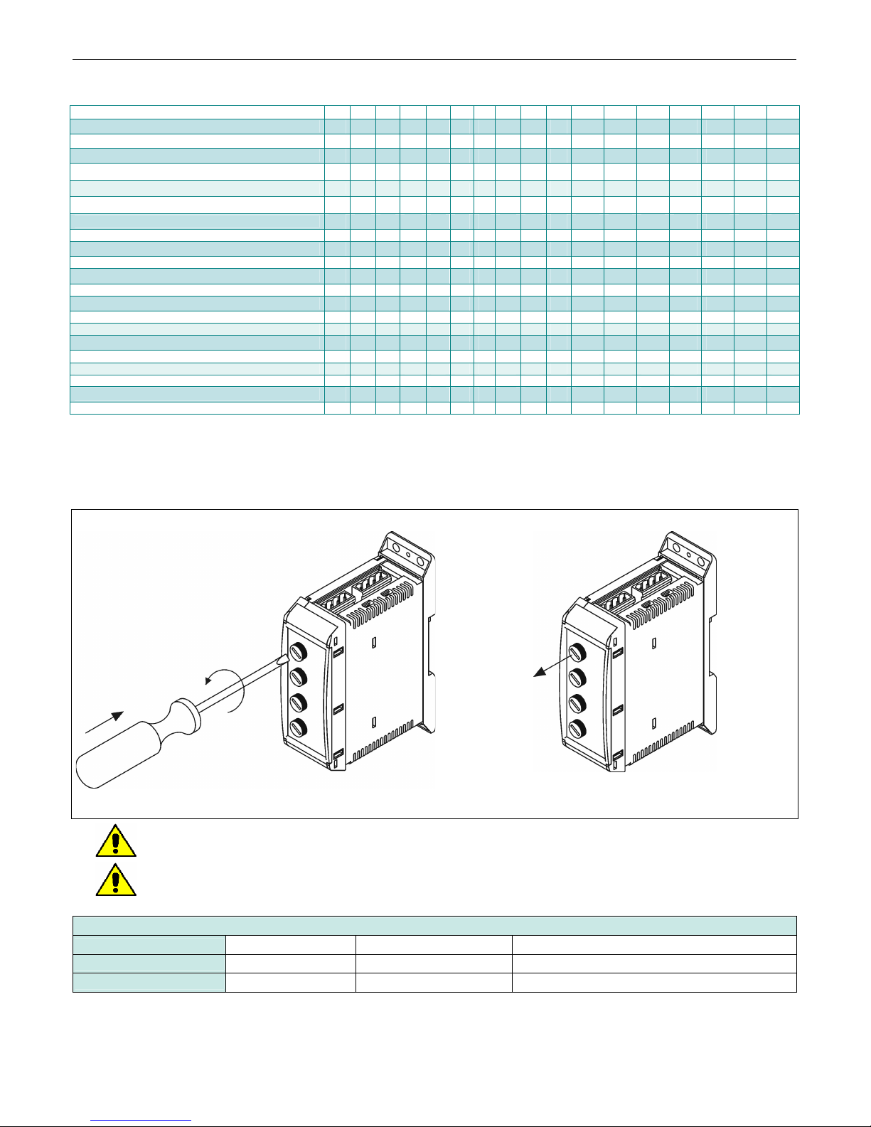
Order Code
1 2 3 4 5 6 - 7 8 9 10 11 12 13 14 15 16
REVO Sx
N°Zone x Current Rating
3,5 A 4 X 0 3
4,5 A 3 X 0 4
7,0 A 2 X 0 7
Max Voltage
240V 2
Input - Firing
SSR – Zero Crossing S Z
Fuse + Fuse Holder
IFH for each phase F
cUl us Approval
none 0
cUl us L
Manual
None 0
Italian 1
English 2
Version
Version1 1
R S _ X _ _ - 2 0 S Z 0 F 0 _ _ 1
Internal Fuse
The thyristor unit must be protected against short circuit by High speed fuses.
The Fuses must have I²t 20% less than thyristor’s I²t.
The warranty of thyristor is null if no proper fuses are used.
Change the Fuses:
Press, turn in counter-clockwise and release Extract the fuse
Caution: High speed fuses are used only for the thyristor protection and can not be used to
protect the installation
Caution: The warranty of thyristor is null if no proper fuses are used.
Spare Fuse Order Code:
REVO 4x3,5A FU5X20-4 Only one pcs. Type 5x20 4A 250V fast 0104004
REVO 3x4,5A FU5X20-5 Only one pcs. Type 5x20 6A 250V fast 0104005
REVO 2x7A FU5X20-8 Only one pcs. Type 5x20 10A 250V fast 0104008
Page 4
CD Automation srl REVO 4x3,5A User’s manual
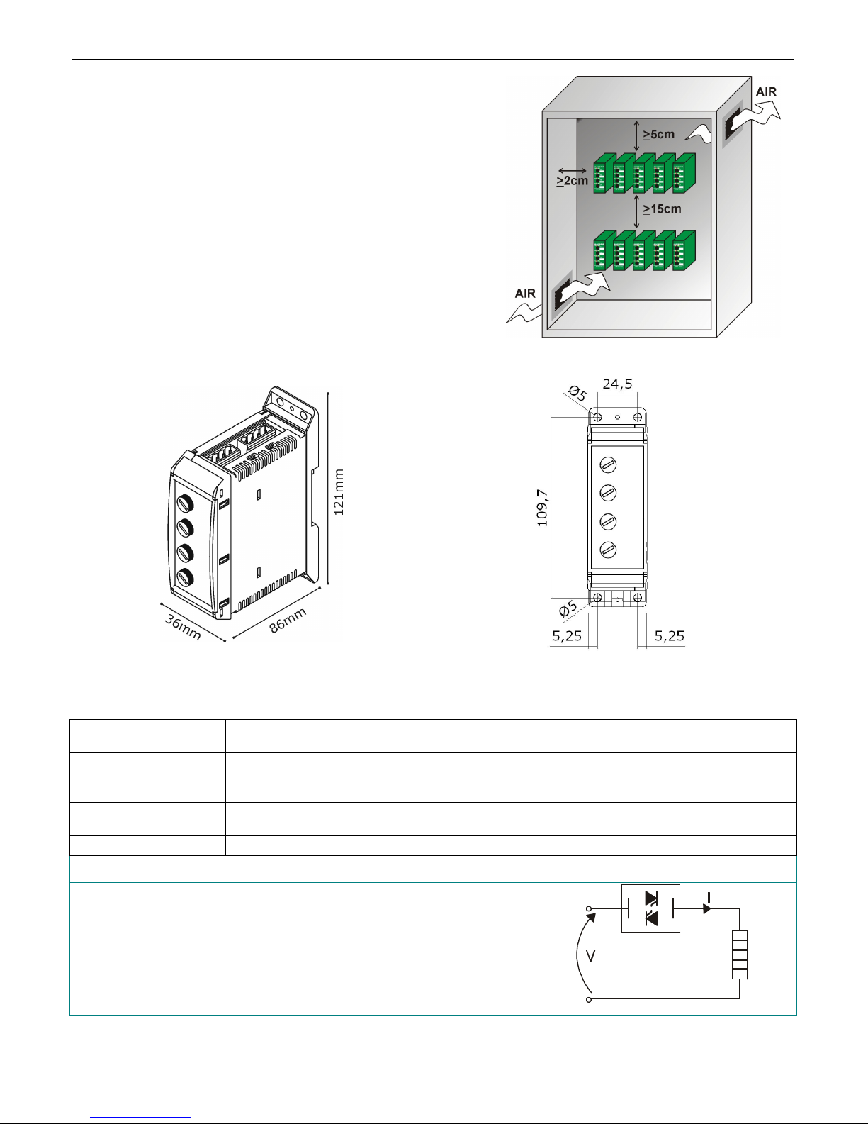
Dimensions and Fixing holes
V
Installation
Before to install the thyristor unit examine for damages or
deficiencies. If any is found, notify the carrier immediately.
Check that the product features shown on unit cover
corresponds to that ordered.
The thyristor unit should be always mounted in vertical
position to improve air cooling on heat-sink.
Maintain minimum distances in vertical and in horizontal as
represented.
Don't install in proximity of hot elements and near units
generating electromagnetic interferences.
When more units are mounted in the same cabinet provide
air circulation as represented.
Sometimes it is necessary to provide a fan to have better air
circulation.
Weight: 0,3Kg
Environmental installation conditions
Ambient temperature
Stocking temperature -25°C to 70°C
Installation place
Altitude
Humidity From 5 to 95% without condense and ice
0-40°C at nominal current.
Over 40°C use the Derating Curve.
Don’t install at direct sun light, where there are conductive dust, corrosive gas,
vibration or water and also in salty environmental.
Up to 1000 meter over sea level. For higher altitude reduce the nominal current of
2% for each 100m over 1000m
Basic Connections
Wiring with resistive load
P
I =
V = Nominal load voltage
I = Nominal load current
P = Nominal load power
Page 5
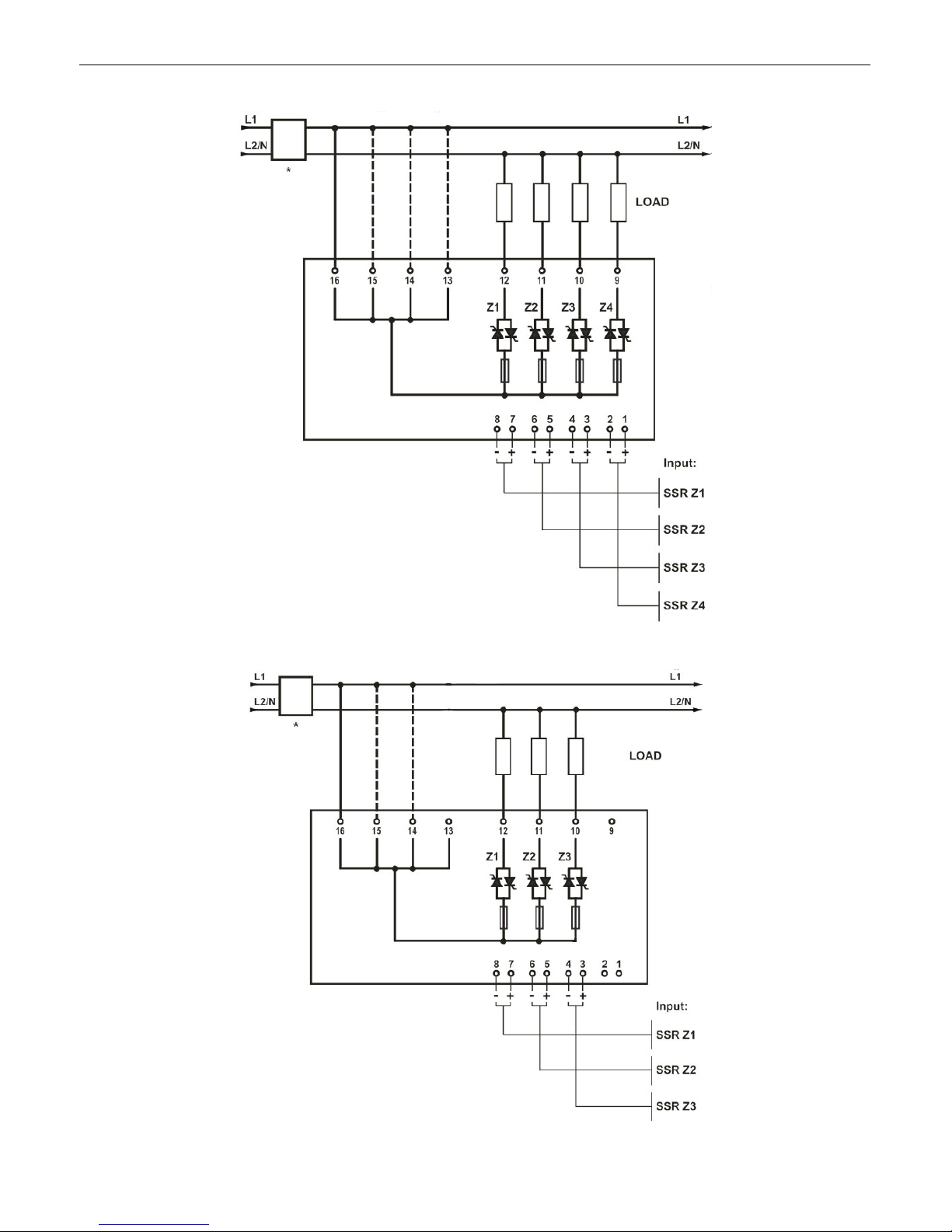
CD Automation srl REVO 4x3,5A User’s manual
Diagram of control connection 4x3,5A
Diagram of control connection 3x4,5A
Page 6
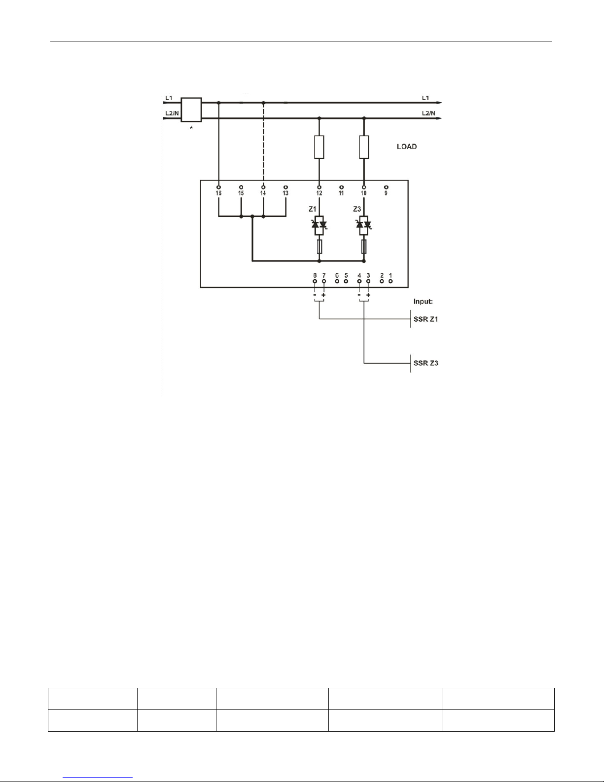
CD Automation srl REVO 4x3,5A User’s manual
Diagram of control connection 2x7A
Note:
• A suitable device must ensure that the unit can be electrically isolated from the supply, this allows
the qualified people to work in safety (*).
• Before connecting or disconnecting the unit check that power and control cables are isolated from
voltage sources
Wiring instructions
The Thyristor unit could be susceptible to interferences lost by near equipments or by the power supply,
for this reason in accord to the fundamental practices rules is opportune take some precautions:
• The coil contactor, the relays and other inductive loads must be equipped with opportune RC filter.
• Use shielded bipolar cables for all the input and output signals.
• The signal cables must not be near and parallel to the power cables.
• Local regulations regarding electrical installation should be rigidly observed.
Use copper cables and wires rated for use at 75°C only.
Command cable dimensions (suggested)
0.5mm² (AWG 18)
Power cable dimensions (suggested)
Each terminal can reach 12A using a wire with 1.5mm² of diameter, if you use all the 4 zones in the ON
condition at the same time, connecting more terminals (13-14-15-16) at the line power
Power cable torque (suggested)
MAX Current
Each terminal
12A
Connector
Type
Estraibile
Connectors
Torque
Lb-in (Nm)
4.42 (0.5) 0.5-1.5 (18-14)
Wire Range
mm²(AWG )
Wire Terminal
Rigid / Flexible
Wire Pin
Page 7
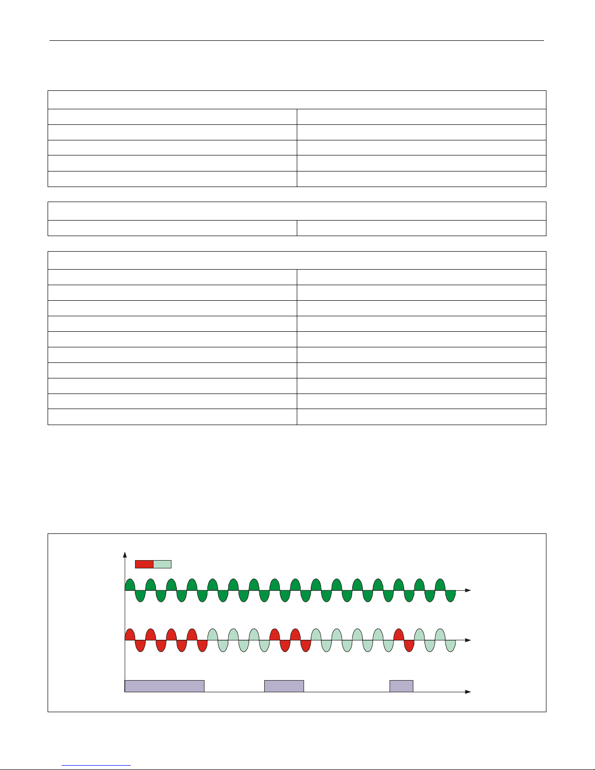
CD Automation srl REVO 4x3,5A User’s manual
VOLTAGE SUPPLY (V)
SSR from controller
Technical Specifications
General features:
Cover and Socket material: PolymericV2
Mounting: DIN bar (thickness type 1mm Max)
Internal Heat-sink: Anodized aluminum
Delay switch ON time: 0.5 period Max
Delay switch OFF time: 0.5 period Max
Input features:
Logic input SSR: 4 ÷ 30Vdc 5mA Max (ON ≥ 4Vdc OFF < 1Vdc)
Power output features:
Current: 4x3,5A – 3x4,5 - 2 x 7A
Voltage range: 24÷230V
Repetitive peak reverse Voltage (230V): 1200
Latching current: 150mA eff
Max peak one cycle (10ms): 230A
Leakage current: 15mA eff
I²T Thyristor value tp=10msec: 610
Frequency range: 47÷70Hz
Power loss (I=Inom): 4x4,2W
Isolation Voltage: 2500Vac
Firing Type
ZC firing mode is used with Logic Output from temperature controllers and the Thyristor operates like a
contactor.
The Cycle time is performed by temperature controller.
ZC minimizes interferences because the Thyristor unit switches ON-OFF at zero voltage.
ON OFF
LOAD VOLTAGE (V)
Page 8
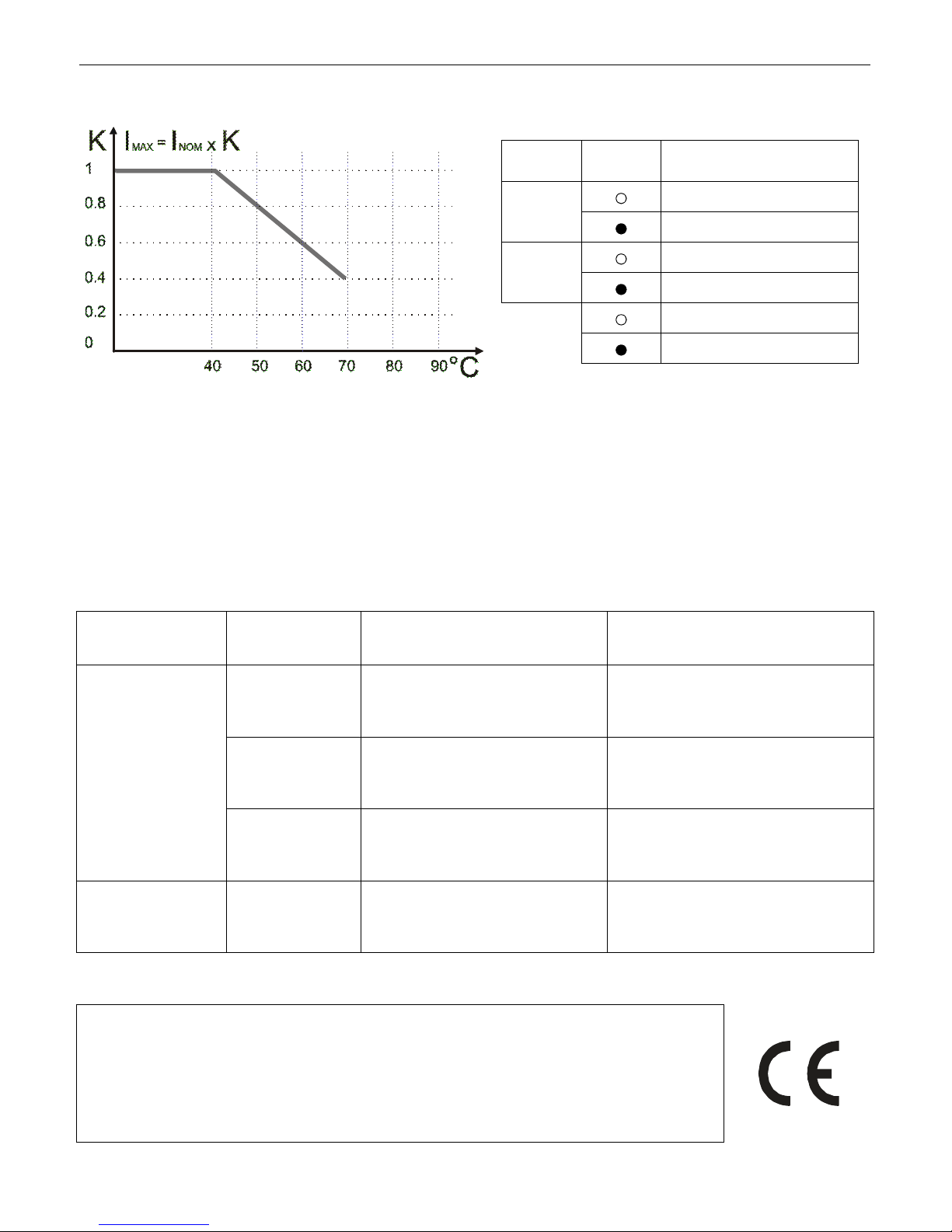
CD Automation srl REVO 4x3,5A User’s manual
Derating Curve Led status and Alarms
LED STATUS
ON
FF
DESCRIPTION
Load IS NOT Powered
Load IS Powered
Fuse OK
Fuse Fault
= OFF
= ON
Maintenance
In order to have correct cooling, the user must clean the heat-sink and the protective grill. The frequency
of this servicing depends on environmental pollution.
Also check periodically if the screw for the power and the control cables are tightened correctly
(See Diagram of control connection)
Trouble Shooting
Small problems sometimes can be solved locally with the help of the below tab of trouble shooting. If you
don’t succeed, contact us or your nearest distributor.
Symptom
Thyristor unit
doesn’t go in
conduction
Load current flows
also with no input
signal
Indication on
front unit
Green LED (ON)
light off
Green LED (ON)
light on
Red LED (FF)
light on
Green LED (ON)
light off
Possible reasons of the
symptom
• No input signal
• Reversed polarities of input
signal
• Load failure
• Load connection interruption
• Thyristor faulty
Red LED (FF) is light off
• Fuse Fault
Green LED (ON) is light on
• Wrong wiring
• Short circuit on thyristor
• Provide to give input signal
• Reverse the input signal polarity
• Check the load
• Check the wiring
• Substitute the faulty thyristor
• Substitute the faulty Fuse
• Check the load wiring
• Substitute the thyristor
Warranty condition
CD Automation gives a 12 months warranty to its products. The warranty is limited to
repairing and parts substitution in our factory and does exclude products not properly
used and fuses.
Warranty does not include products with serial numbers deleted.
The faulty product should be shipped to CD Automation at customer’s cost and our
Service will evaluate if product is under warranty terms.
Substituted parts remain of CD Automation property.
CD-Eng-REVO_Sx-01
Actions
 Loading...