

Page 1
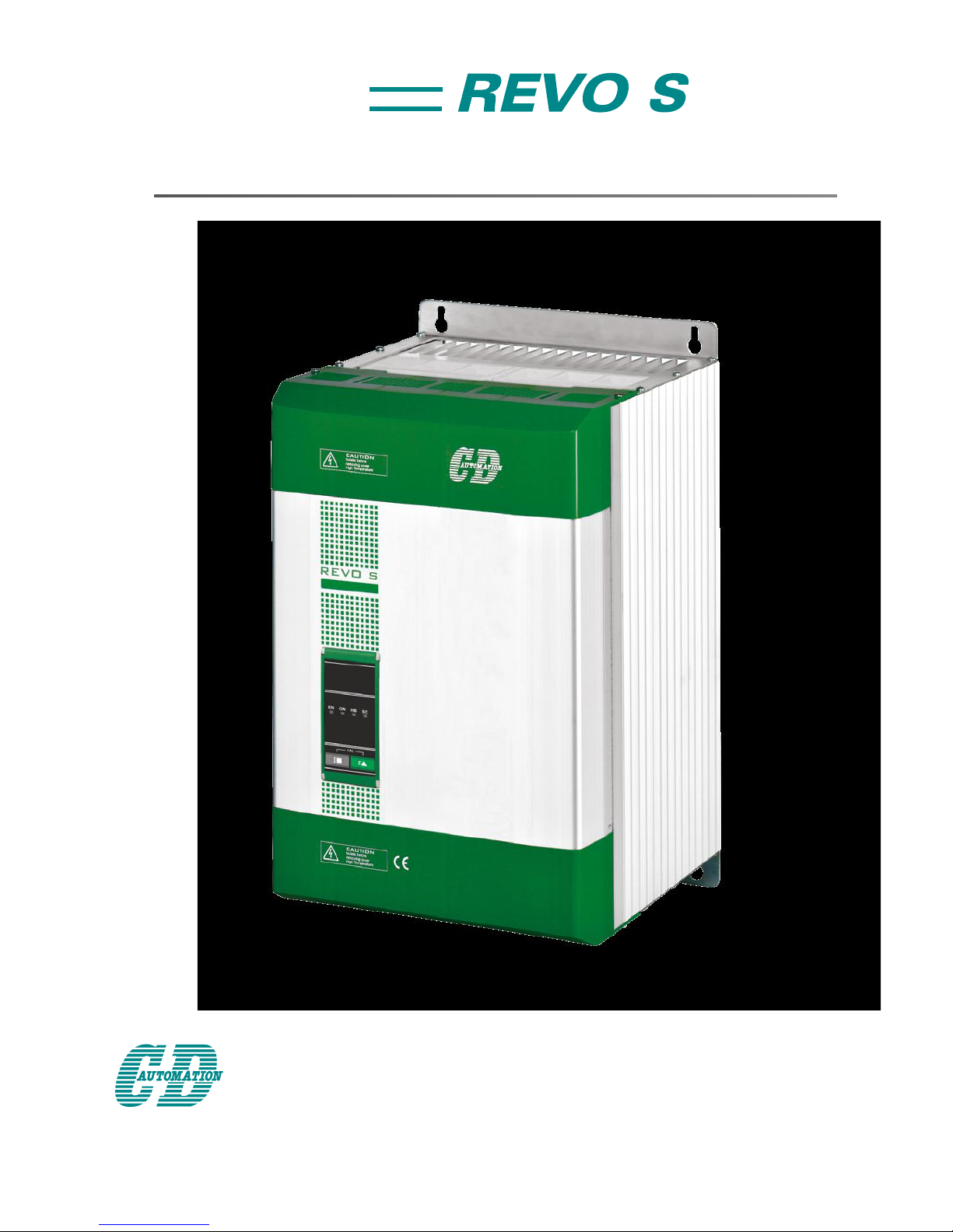
USER’S MANUAL
Rev. 03/2019
2PH
001
M-RS2-60-800-690V
690V
from 60A to 800A
CD Automation S.r.l.
Via Picasso, 34/36 - 20025 Legnano (MI)- Italy
Tel. +39 0331 577479 - Fax +39 0331 579479
E-mail: [email protected] - Web: www.cdautomation.com
Page 2

Page 3
Declaration of conformity
Declaration of conformity-Dichiarazione di Conformità
PRODUCT MANUFACTURER/ PRODUTTORE:
CD Automation S.R.L.
Controllers, Drives & Automation
Via Picasso, 34/36 - 20025 Legnano (MI)- Italy
P.I. 08925720156 -Tel. +39 0331 577479 - Fax +39 0331 579479
E-mail: [email protected] - Web: www.cdautomation.com
Declare that the product / Dichiara che il prodotto:
Revo S 2Ph 690V 60-800A
PRODUCT DESCRIPTION: Electric power control
SCOPE OF APPLICATION: Thermal control process
DESCRIZIONE DEL PRODOTTO: Unità di controllo potenza elettrica
UTILIZZO: Controllo processi termici
FULFILS THE REQUIREMENTS OF THE STANDARD:
Electrical safety Standard EN60947-1: 2007 + A1 2011, A2 2014
EN60947-4-3: 2014
Generic Emission standard EN60947-4-3: 2014 Group 1 Class A emissions
Generic Immunity standard EN60947-4-3: 2014 Industrial Immunity
SODDISFA I REQUISITI DELLA NORMA:
Specica di sicurezza EN60947-1: 2007 + A1 2011, A2 2014
EN60947-4-3: 2014
Specica sulle emissioni EN60947-4-3: 2014 gruppo 1 emissioni classe A
Specica sulle Immunità EN60947-4-3: 2014 Immunità industriale
CDAutomation declares that the products above mentioned are conforming to the directive
CDAutomation dichiara che i prodotti sopra menzionati sono conformi alla direttiva
Alla direttiva Bassa Tensione (low Voltage) EMC directive updated 2014/30/EU,
Low Voltage Directive updated 2014/35/EU
Issued on: 20/03/2017
Data di emissione: 20/03/2017
Amministratore Unico e
Legale Rappresentante
Claudio Brizzi
Page 4
4
REVO S 2PH from 60A to 800A - 690V User’s manual
Important warnings for safety
This chapter contains important information for the safety. The not observance of these instructions may result
in serious personal injury or death and can cause serious damages to the Thyristor unit and to the components
system included.
The installation should be performed by qualied persons.
In the manual are used symbols to give more evidence at the notes of safety and operativity for the attention
for the user:
This icon is present in all the operational procedures where the Improper
operation may result in serious personal injury or death by Electrical Shock
Hazard Symbol (a lightning bolt in a triangle) precedes an electric shock hazard
CAUTION or WARNING safety statement.
Warning or Hazard that needs further explanation than the label on unit can
provide. Consult User’s Guide for further information.
Unit is compliant with European Union directives.
See Declaration of Conformity for further details on Directives and Standards
used for Compliance.
If available, unit is a Listed device per Underwriters Laboratories. It has been
investigated to ANSI/UL® 508 standards for Industrial Control Switches and
equivalent to CSA C22.2 #14.
For more detail search for File E231578 on www.ul.com
ESD Sensitive product, use proper grounding and handling techniques when
installing or servicing product.
Do not throw in trash, use proper recycling techniques or consult manufacturer
for proper disposal.
A “NOTE” marks a short message to alert you to an important detail.
A “CAUTION” safety alert appears with information that is important for protecting your equipment and
performance. Be especially careful to read and follow all cautions that apply to your application.
A “WARNING” safety alert appears with information that is important for protecting you, others and equipment
from damage. Pay very close attention to all warnings that apply to your application.
Safety notes
WARNING! To avoid damage to property and equipment, injury and loss of life, adhere to applicable
electrical codes and standard wiring practices when installing and operating this product. Failure to do
so could result in damage, injury and death.
AVERTISSEMENT! Pour éviter d’endommager la propriété et l’équipement, les blessures et la perte
de vie, respecter les codes électriques en vigueur et les pratiques de câblage standard au moment
de l’installation et de l’utilisation de ce produit. Dans le cas contraire, cela peut entraîner la mort, des
blessures graves ou des dommages.
IND. CONT. EQ.
E231578 2RD5
Page 5
REVO S 2PH from 60A to 800A - 690V User’s manual
5
WARNING! All service including inspection, installation, wiring, maintenance, troubleshooting, fuse
or other user serviceable component replacement must be performed only by properly qualied
personnel. Service personnel must read this manual before proceeding with work. While service is
being performed unqualied personnel should not work on the unit or be allowed in the immediate
vicinity.
AVERTISSEMENT! Tous les services, y compris l’inspection, l’installation, le câblage, l’entretien, le
dépannage, le remplacement de fusibles ou d’autres composants pouvant être réparés par l’utilisateur,
doivent être eectués uniquement par un personnel diment qualié. Le personnel de service doit lire ce
manuel avant d’eectuer tout travail. Pendant que l’entretien est exécuté, tout personnel non qualié ne
doit eectuer de travail sur l’appareil ni se trouver a proximité.
WARNING! When in use the power controller is connected to dangerous voltages. Do not remove the
protective covers without rst disconnecting and preventing power from being restored while servicing
the unit.
AVERTISSEMENT! Au moment de l’utilisation, le régulateur de puissance est connecté a des tensions
dangereuses. Ne retirer aucun couvercle de protection sans d’abord débrancher l’appareil et ainsi
empêcher l’alimentation d’être rétablie pendant l’entretien.
WARNING! Do not use in aerospace or nuclear applications.
AVERTISSEMENT! Ne pas utiliser pour les applications aérospatiales ou nucléaires.
WARNING! The power controller’s protection rating is IP20 with all covers installed and closed. It must
be installed in an enclosure that provides all the necessary additional protections appropriate for the
environment and application.
AVERTISSEMENT! L’indice de protection du régulateur de puissance est de IP20 lorsque les couvercles
sont installés et fermés. L’appareil doit être installé dans une enceinte qui assure toute la protection
supplémentaire nécessaire pour l’environnement et l’application.
WARNING! Ground the power controller via the provided protective earth grounding terminal. Verify
ground is within impedance specications. This should be veried periodically.
AVERTISSEMENT! Mise a la terre du régulateur de puissance par le biais de la borne de prise de terre
de protection fournie. Vérier que la prise de terre est conforme aux spécications de l’impédance. Cela
doit être vérié périodiquement.
WARNING! Electric Shock Hazard: when the power controller has been energized, after shutting o the
power, wait at least one minute for internal capacitors to discharge before commencing work that brings
you in to contact with power connections or internal components.
AVERTISSEMENT! Risque de décharges électriques: lorsque le régulateur de puissance est mis sous
tension, après avoir été éteint, attendre au moins une minute pour que les condensateurs internes se
déchargent avant de commencer tout travail incluant le contact avec les connexions électriques ou les
composants internes.
WARNING! The installation must be protected by electromagnetic circuit breakers or by fuses. The
semiconductor fuses located inside the power controller are classied for UL as supplementary
protection for semiconductor devices. They are not approved for branch circuit protection.
AVERTISSEMENT! L’installation doit être protégée par des disjoncteurs électromagnétiques ou des
fusibles. Les fusibles pour semi-conducteurs situés a l’intérieur du régulateur de puissance sont classés
UL comme protection supplémentaire pour les dispositifs pour semi-conducteurs. Ils ne sont pas
approuvés pour la protection des circuits de dérivation.
WARNING! When making live voltage or current measurements, use proper personal protective
equipment for the voltages and arc-ash potentials involved.
AVERTISSEMENT! Au moment de relever des mesures de tension ou de courant en direct, utiliser un
équipement de protection individuelle approprié pour les tensions et les potentiels d’arc électrique
concernés.
Page 6
6
REVO S 2PH from 60A to 800A - 690V User’s manual
WARNING! Verify the voltage and current ratings of the power controller are correct for the application.
AVERTISSEMENT! Vérier que les valeurs de tension et de courant du régulateur de puissance sont
correctes pour l’application.
CAUTION: To avoid compromising the insulation, do not bend wire or other components beyond their
bend radius specications.
ATTENTION: Pour éviter de compromettre l’isolation, ne pas plier le l ou tout autre composant au-delà
de ses spécications en matière de rayon de courbure.
CAUTION: Protect the power controller from high temperature, humidity and vibrations.
ATTENTION: Protéger le régulateur de puissance contre les températures élevées, l’humidité et les
vibrations.
CAUTION: The power controller warranty is void if the tested and approved fuses are not used.
ATTENTION: La garantie du régulateur de puissance est nulle si aucun fusible testé et approuvé n’est
utilisé.
CAUTION: Only trained and authorized personnel should access and handle the internal electronics and
they must follow proper electro-static prevention procedures.
ATTENTION: Seul le personnel formé et autorisé peut accéder aux composants électroniques internes
et les gérer, et il doit se conformer a des procédures de prévention électrostatique appropriées.
CAUTION: Install an appropriately sized RC lter across contactor coils, relays and other inductive
loads.
ATTENTION: Installer un ltre RC de dimensions appropriées sur les bobines du contacteur, les relais et
autres charges par induction.
CAUTION: The thyristor units here described have been designed for use with sinusoidal networks with
nominal frequency 50-60 Hz. Any application with NON-SINUSOIDAL, distorted or disturbed networks
could compromise the correct operation of the unit.
ATTENTION: Les unités de thyristors décrites ici ont été conçues pour être utilisées avec des réseaux
sinusoïdaux d’une fréquence nominale de 50 à 60 Hz. Toute application utilisant des réseaux NON
SINUSOÏDAUX, déformés ou perturbés peut compromettre le bon fonctionnement de l’appareil.
NOTE: Provide a local disconnect to isolate the power controller for servicing.
REMARQUE: Fournir une déconnexion locale an d’isoler le régulateur de puissance pour l’entretien.
NOTE: The nominal current is specied for ambient temperatures at or below 40° C. Ensure the application
design allows for adequate cooling of each power controller. The power controller must be mounted
vertically. The cooling design must prevent air heated by one power controller from causing power
controllers mounted above to exceed the ambient operating temperature limit. When power controllers
are mounted side by side allow a minimum spacing of 15mm between them.
REMARQUE: Le courant nominal est précisé pour des températures ambiantes égales ou inférieures
a 40°C. S’assurer que la conception de l’application permette le refroidissement adéquat de chaque
régulateur de puissance. Le régulateur de puissance doit être monté verticalement. La conception de
refroidissement doit empêcher l’air chaué par le régulateur de puissance de dépasser la limite de
température de fonctionnement ambiante de la part des régulateurs de puissance montés au-dessus.
Lorsque les régulateurs de puissance sont montés côte a côte, il faut conserver un espacement minimal
de 15 mm entre les deux.
NOTE: Use only copper cables and wires rated for use at 75°C or greater.
REMARQUE: N’utiliser que des cables et des ls en cuivre pour l’utilisation a 75°C ou plus.
Page 7
REVO S 2PH from 60A to 800A - 690V User’s manual
7
Maintenance
In order to have a corrected cooling, the user must clean the heat-sink and the protective grill of the fans. The
frequency of this servicing depends on environmental pollution.
Also check periodically if the screw for the power cables and safety earth are tightened correctly
(See Connection Diagram).
Warranty condition
Producer gives a 12 months warranty to its products.
The warranty is limited to repairing and parts substitution in our factory and does
exclude products not properly used and fuses.
Warranty does not include products with serial numbers deleted. The faulty
product should be shipped to Producer at customer’s cost and our Service will
evaluate if product is under warranty terms.
Substituted parts remain of Producer property.
Return Material Authorization (RMA)
Customers wishing to return any items, whether they are incorrectly supplied, faulty or damaged in transit,
must rst complete a Return Material Authorisation (RMA) form to obtain an RMA number from the Service
Department.
A full repair service is available for customers. Prior to submitting the RMA form and returning products,
customers are recommended to contact the technical support team to determine whether the issue can be
resolved with telephone support.
How the RMA service works
The RMA form and details are availableon our web sites:
https://www.cdautomation.com/returns-material-authorisation/
When completing the RMA form, please be as specic as possible about the problem, including any pertinent
application details. The more information given, the more quickly and more thoroughly the problem can be
solved. The minimum information required is:
1. The Full Model Number
2. Quantity of units being returned
3. The units Serial Number(s)
4. A description of the problem ( “faulty” or “unknown” is not sucient)
Page 8
8
REVO S 2PH from 60A to 800A - 690V User’s manual
Declaration of conformity . . . . . . . . . . . . . . . . . . . . . . . . . . . . . . 3
Important warnings for safety . . . . . . . . . . . . . . . . . . . . . . . . . . . 4
Maintenance . . . . . . . . . . . . . . . . . . . . . . . . . . . . . . . . . . . . . . 7
Basic Connections and sizing . . . . . . . . . . . . . . . . . . . . . . . . . . 10
Identication and Order Code . . . . . . . . . . . . . . . . . . . . . . . . . . .11
2.1 Identication of the unit . . . . . . . . . . . . . . . . . . . . . . . . . . . . . . . . . 11
2.2 Order Code. . . . . . . . . . . . . . . . . . . . . . . . . . . . . . . . . . . . . . . . . . 12
Technical Specications. . . . . . . . . . . . . . . . . . . . . . . . . . . . . . 13
3.1 General features . . . . . . . . . . . . . . . . . . . . . . . . . . . . . . . . . . . . . . 13
3.2 Input features . . . . . . . . . . . . . . . . . . . . . . . . . . . . . . . . . . . . . . . . 13
3.4 Fan Specication . . . . . . . . . . . . . . . . . . . . . . . . . . . . . . . . . . . . . . 14
3.5 Environmental installation conditions . . . . . . . . . . . . . . . . . . . . . . . . 14
3.6 Derating Curve and Thermal conditions . . . . . . . . . . . . . . . . . . . . . . . 14
3.7 Calculating ow capacity of the fan. . . . . . . . . . . . . . . . . . . . . . . . . . 14
Installation . . . . . . . . . . . . . . . . . . . . . . . . . . . . . . . . . . . . . . 15
4.1 Dimensions and weight . . . . . . . . . . . . . . . . . . . . . . . . . . . . . . . . . . 16
4.2 Fixing holes . . . . . . . . . . . . . . . . . . . . . . . . . . . . . . . . . . . . . . . . . 17
Wiring instructions . . . . . . . . . . . . . . . . . . . . . . . . . . . . . . . . . 18
5.1 Removing the cover . . . . . . . . . . . . . . . . . . . . . . . . . . . . . . . . . . . . 18
5.2 Line power and Load cable/bar dimensions and torque (suggested). . . . 18
5.3 Cable dimensions (suggested) of Earth and of the Command Terminals . . 19
5.4 Terminals Positions . . . . . . . . . . . . . . . . . . . . . . . . . . . . . . . . . . . . 19
5.5 Power Terminals . . . . . . . . . . . . . . . . . . . . . . . . . . . . . . . . . . . . . . 20
5.6 Control Terminals. . . . . . . . . . . . . . . . . . . . . . . . . . . . . . . . . . . . . . 21
5.7 Schematic . . . . . . . . . . . . . . . . . . . . . . . . . . . . . . . . . . . . . . . . . . 22
5.8 Connection Diagram for 3 phases (control on 2 phases). . . . . . . . . . . . . 24
Indice
1
4
5
2
3
Page 9

REVO S 2PH from 60A to 800A - 690V User’s manual
9
Led status and alarms . . . . . . . . . . . . . . . . . . . . . . . . . . . . . . . 25
Heater Break alarm and SCR short circuit . . . . . . . . . . . . . . . . . . 26
7.1 Heater break Calibration procedure. . . . . . . . . . . . . . . . . . . . . . . . . . 26
Input Setting . . . . . . . . . . . . . . . . . . . . . . . . . . . . . . . . . . . . . 27
Burst Firing settings . . . . . . . . . . . . . . . . . . . . . . . . . . . . . . . . 28
Firing type . . . . . . . . . . . . . . . . . . . . . . . . . . . . . . . . . . . . . . . 29
10.1 Zero Crossing. . . . . . . . . . . . . . . . . . . . . . . . . . . . . . . . . . . . . . . . 29
10.2 Burst Firing . . . . . . . . . . . . . . . . . . . . . . . . . . . . . . . . . . . . . . . . . 29
Supply the electronic board . . . . . . . . . . . . . . . . . . . . . . . . . . . 30
Internal Fuse . . . . . . . . . . . . . . . . . . . . . . . . . . . . . . . . . . . . . 31
6
7
8
9
10
11
12
Page 10
10
REVO S 2PH from 60A to 800A - 690V User’s manual
Basic Connections and sizing
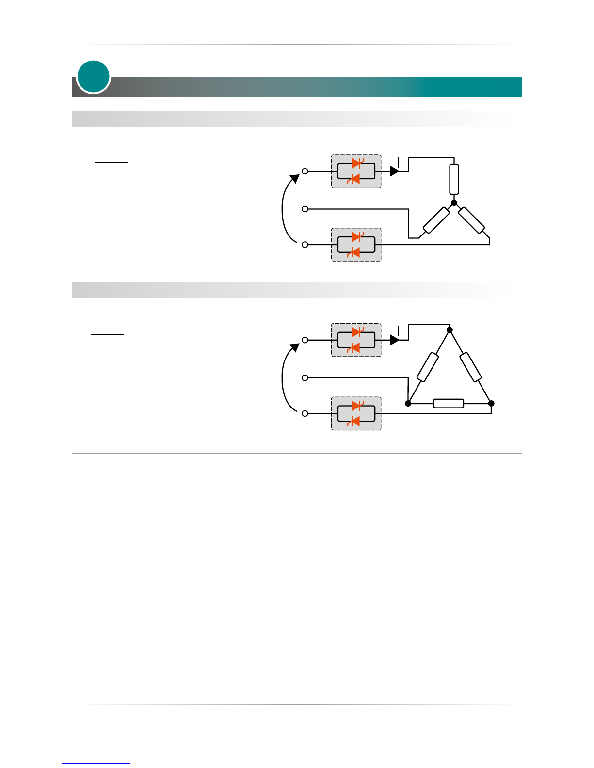
Star wiring with resistive load (control on two phases with REVO S-2PH)
V = Nominal voltage of the load
I = Nominal current of the load
P = Nominal power of the load
Delta wiring with resistive load (control on two phases with REVO S-2PH)
V = Nominal voltage of the load
I = Nominal current of the load
P = Nominal power of the load
1
I=
P
1,73V
I=
P
1,73V
V
V
Page 11

REVO S 2PH from 60A to 800A - 690V User’s manual
11
Identification and Order Code
2.1 Identication of the unit
Caution: Before to install, make sure that the Thyristor unit have not damages. If the product
has a fault, please contact the dealer from which you purchased the product.
The identication’s label give all the information regarding the factory settings of the Thyristor unit, this label is
on the unit, like represented in gure.
Verify that the product is the same thing as ordered.
2
Page 12
12
REVO S 2PH from 60A to 800A - 690V User’s manual
2.2 Order Code
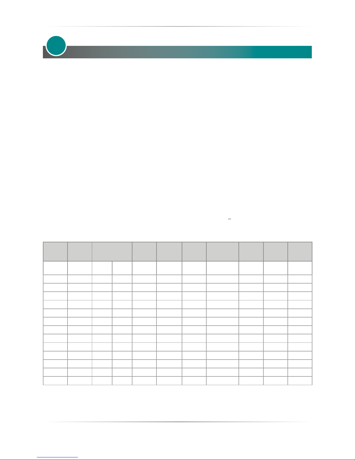
1 2 3 4 5 6 7 8 9 10 11 12 13 14 15 16
REVO S 2PH R S 2 _ _ _ - _ _ _ _ _ _ _ _ _ _
CURRENT FUSES 4 5 6
description description code
60A Fixed Fuses Included 0 6 0
90A Fixed Fuses Included 0 9 0
120A Fixed Fuses Included 1 2 0
150A Fixed Fuses Included 1 5 0
180A Fixed Fuses Included 1 8 0
210A Fixed Fuses Include d 2 1 0
300A Fixed Fuses Included 3 0 0
400A Fixed Fuses Included 4 0 0
450A Fixed Fuses Included 4 5 0
500A Fixed Fuses Included 5 0 0
600A Fixed Fuses Included 6 0 0
700A Fixed Fuses Included 7 0 0
800A Fixed Fuses Included 8 0 0
MA X VO LTAGE 7
description code
480V 4
600V 6
690V 7
VOLTAGE SUPPLY AUX 8
Main Supply Voltage Aux Voltage Range code
100/1 20Vac 90 to 135V Vac 1
200/2 08/230/2 40Vac 180 to 265V Vac 2
277 Vac 238 to 330V Vac 3
3 80/4 1 5 /48 0Va c 342 to 528V Va c 5
600Vac 540 to 759V Vac 6
690Va c 540 to 75 9V Vac 7
INPUT 9
description code
SSR S
0:10V V
4:20mA A
FIRING 10
description code
Zero Crossin g Z
Burst Fi ring 4 Cyc les On at 50% Powe r Demand 4
Burst Fi ring 8 Cyc les On at 50% Powe r Demand 8
Burst Fi ring 16 Cycles On at 50% P ower Dema nd 6
CONTROL MODE 11
description code
Open Lo op 0
FUSES & OPTION 12
description code
Fixed Fuse s Std for all Un its > 40A F
Fixed Fuse s Std + CT + HB H
FAN VOLTA GE 13
description code
Fan 115Vac Opt ion 1
Fan 230Vac Std Versi on 2
Fan 24Vdc Optio n 3
APPROVALS 14
description code
CE EMC For Euro pean Ma rket 0
MANUAL 15
description code
None 0
Italian 1
English 2
German 3
Frenc h 4
VERSION 16
description code
Std unit wi th one fu se only 1
High Sensitivity HB below 5A 5
Note: The 690V unit is available with CE Only
Page 13
REVO S 2PH from 60A to 800A - 690V User’s manual
13
Technical Specifications
3.1 General features
Cover and Socket material: PolymericV2
Utilization Category: AC-51 AC-55b
IP Code: 20
Method of Connecting: Load in Delta, Load in Star
Auxiliary voltage:
Order code RS2_ _ _ -_1 = line voltage 100/120V transformer range 90:135V (8 VA Max)
Order code RS2_ _ _ -_2 = line voltage 200/208/220/230/240V transformer range 180:265V (8 VA Max)
Order code RS2_ _ _ -_3 = line voltage 277 transformer range 238:330V (8 VA Max)
Order code RS2_ _ _ -_5 = line voltage 380/400/415/440/480V transformer range 342:528V (8 VA Max)
Order code RS2_ _ _ -_6 = line voltage 600V transformer range 540:759V (8 VA Max)
Order code RS2_ _ _ -_7 = line voltage 690V transformer range 540:759V (8 VA Max)
Relay output for Heater Break Alarm
(only with HB option): 0.5A a 125VAC
3.2 Input features
Analogic input 0 ÷ 10Vdc impedance 15 K ohm
Analogic input 4 ÷ 20mA impedance 100 ohm
POT 10 K ohm min.
Digital Input 4 ÷ 24Vdc 5mA Max (ON >4Vdc OFF <1Vdc)
3HZ Max duty cycle min. 100 ms
3.3 Output features (power device)
Current
Nominal
Voltage
range (Ue)
Repetitive peak
reverse voltage
(Uimp)
Latching
current
Max peak
one cycle
Leakage
current
FUSE I2T value
Suggested A2s
(at690V)
Frequency
range
Power loss
Thyristor +
Fuse
Isolation
Voltage
(Ui)
(A) (V) (480V) (690V) (mAe) (10msec.)
(A)
(mAe) tp=10msec (Hz) I=Inom (W) Vac
60A 24÷600 1600 1800 600 1900 15 16940 47÷70 205 3000
90A 24÷600 1600 1800 600 1900 15 16940 47÷70 290 3000
120A 24÷600 1600 1800 600 1900 15 16940 47÷70 398 3000
150A 24÷600 1600 1800 400 1900 15 27500 47÷70 409 3000
180A 24÷600 1600 1800 400 1900 15 48400 47÷70 486 3000
210A 24÷600 1600 1800 400 1900 15 84700 47÷70 598 3000
300A 24÷600 1600 1800 400 1900 15 79750 47÷70 903 3000
400A 24÷600 1600 1800 200 7820 15 236500 47÷70 1092 3000
450A 24÷600 1600 1800 200 7820 15 338800 47÷70 1259 3000
500A 24÷600 1600 1800 200 7820 15 338800 47÷70 1407 3000
600A 24÷600 1600 1800 200 7820 15 462000 47÷70 1528 3000
700A 24÷600 1600 1800 200 7820 15 462000 47÷70 1753 3000
800A 24÷600 1600 1800 200 7820 15 387200 47÷70 2281 3000
3
Page 14
14
REVO S 2PH from 60A to 800A - 690V User’s manual
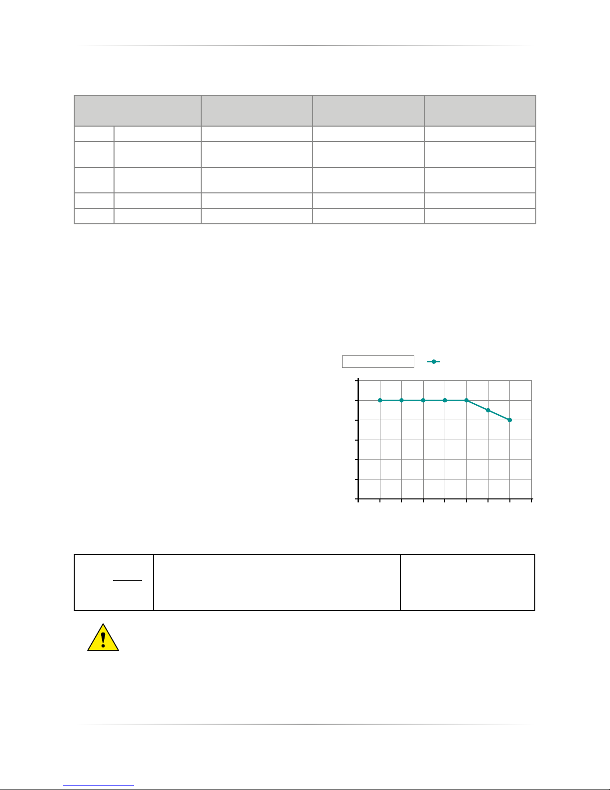
3.4 Fan Specication
Size
Number of fans
230Vac Standard
Number of fans
115Vac Option
Number of fans
24Vdc Option
S11 60A, 90A One Fan - 16W One Fan - 14W One Fan - 7W
S13
120A, 150A, 180A,
210A
Two Fans - (16W x 2) 32W Two Fans - (14W x 2) 28W Two Fans - (7W x 2) 14W
S14
300A, 400A, 500A,
600A
Two Fans - (16W x 2) 32W Two Fans - (14W x 2) 28W Two Fans - (7W x 2) 14W
S14 450A, 700A Four Fans - (16W x 4) 64W Four Fans - (14W x 4) 56W Four Fans - (7W x 4) 28W
S16 800A Four Fans - (16W x 4) 64W Four Fans - (14W x 4) 56W Four Fans - (7W x 4) 28W
3.5 Environmental installation conditions
Ambient temperature 0-40°C (32-104°F) at nominal current. Over 40°C (104°F) use the derating curve.
Storage temperature -25°C to 70°C -13°F to 158°F
Installation place Don’t install at direct sun light, where there are conductive dust, corrosive gas,
vibration or water and also in salty environmental.
Altitude Up to 1000 meter over sea level. For higher altitude reduce the nominal current of
2% for each 100m over 1000m
Humidity From 5 to 95% without condense and ice
Pollution Level Up to 2nd Level ref. IEC 60947-1 6.1.3.2
3.6 Derating Curve and Thermal conditions
The nominal current of the units in specication are referred
to continuos service at 40°C ambient temperature. For higher
temperature multiply the nominal current times derating
coecient K here represented:
3.7 Calculating ow capacity of the fan
All the thyristor units when are in conduction produces power
loss that is dissipated inside cubicle in terms of heating. Due
to this fact the internal temperature of cubicle is higher than
ambient temperature. To be cooled the thyristor need of
fresh air cooling and to do it is normally used a fan mounted
on the front door or on the roof of the cabinet.
Procedure to size Fan air mass ow (V): see power loss for
each thyristor and fuse mounted indicated in the manual
related to the current (Output feature and Internal fuse
Chapter)
Qv = total power losses (w) (thyristor + fuse power loss)
ta = ambient temperature (°C)
tc = cabinet temperature (°C)
V = fan air mass ow (m3/h)
f = altitude coecient (see table on right)
Altitude
0:100 meters f = 3.1 m3k/Wh
100:250 meters f = 3.2 m3k/Wh
250:500 meters f = 3.3 m3k/Wh
500:750 meters f = 3.4 m3k/Wh
The formulas used are for information only and is not a substitute for a proper thermal
rating done by a qualied person.
V=f *
Qv
tc-ta
l max = l nominal x K
1
15 20 25 30 35 40 45 50 55
1,2
1
0,8
0,6
0,4
0,2
0
1 1 1 1
0,9
0,8
K
CABINET TEMPERATURE °C
Derating
For higher cabinet temperature
contact the producer of the unit
Page 15
REVO S 2PH from 60A to 800A - 690V User’s manual
15
Installation
Before to install, make sure that the Thyristor unit have not
damages.
If the product has a fault, please contact the dealer from which
you purchased the product. Verify that the product is the same
thing as ordered.
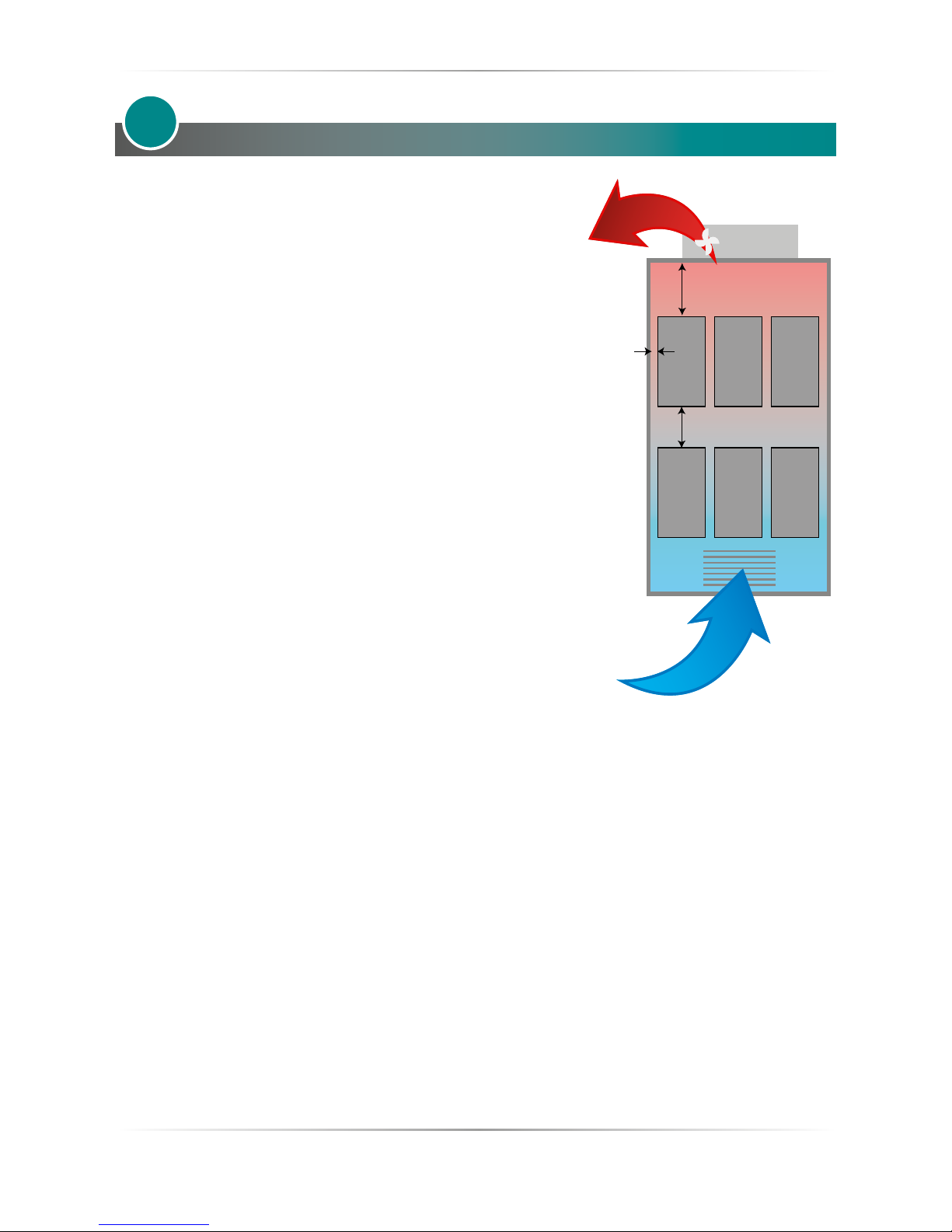
The Thyristor unit must be always mounted in vertical position to
improve air cooling on heat-sink.
Maintain the minimum distances (*) in vertical and in
horizontal as represented, this area must be free from obstacle
(wire, copper bar, plastic channel).
When more unit has mounted inside the cabinet maintain the air
circulation like represented in gure without obstacle for the air
ow.Is necessary to install a fan to have better air circulation as
calculated previously.
*30 cm
*20 cm
*2 cm
AIR FLOW IN (V)
AIR FLOW OUT (V)
FAN
in aspiration
Air Grid
4
The V Air ow must be equal or more than the value calculated.
If the cabinet fan mounted by the customer have an air ow lower than the correct value the warranty
will decay.
Page 16
16
REVO S 2PH from 60A to 800A - 690V User’s manual
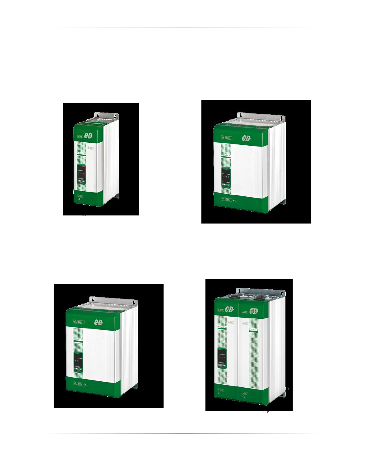
4.1 Dimensions and weight
REVO-S 2PH
60A÷90A (S11)
W 137mm - H 440mm - D 270mm
Weight 10,5Kg
REVO-S 2PH
120A÷210A (S13)
W 262mm - H 440mm - D 270mm
Weight 18Kg
REVO-S 2PH
800A (S16)
W 275mm - H 560mm - D 270mm
Weight 22,5Kg
REVO-S 2PH
300A÷700A (S14)
W 262mm - H 520mm - D 270mm
Weight 22,5Kg
W
W
W
W
D
D
D
D
H
H
H
H
Page 17
REVO S 2PH from 60A to 800A - 690V User’s manual
17
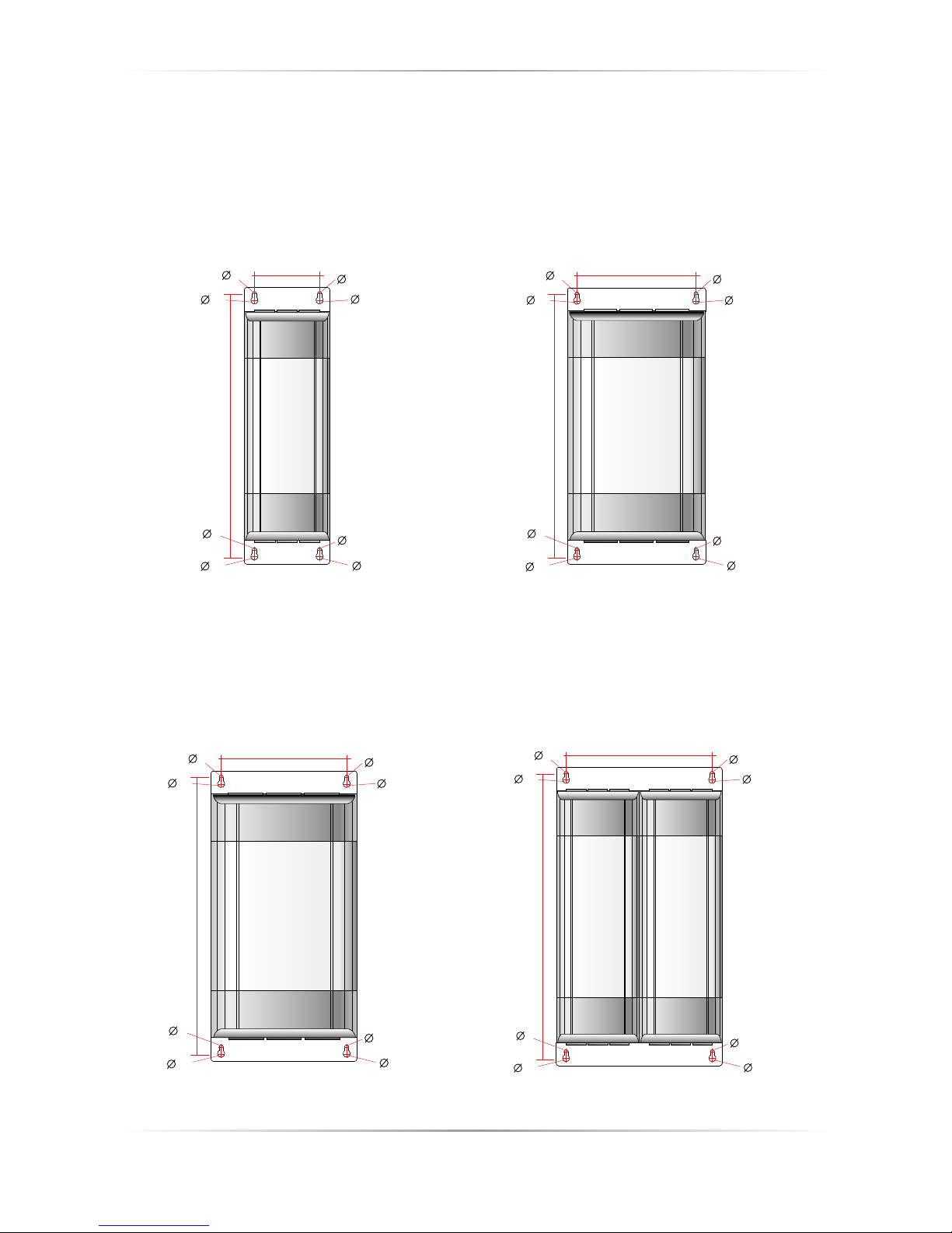
4.2 Fixing holes
REVO-S 2PH
300A÷700A (S14)
REVO-S 2PH
60A÷90A (S11)
REVO-S 2PH
800A (S16)
REVO-S 2PH
120A÷210A (S13)
7
12
7
12
7
7
12
12
222
490
7
12
7
12
7
7
12
12
235
530
7
12
7
12
7
7
12
12
97
410
7
12
7
12
7
7
12
12
222
410
Page 18
18
REVO S 2PH from 60A to 800A - 690V User’s manual
Wiring instructions
The Thyristor unit could be susceptible to interferences lost by near equipments or by the power supply, for
this reason in accord to the fundamental practices rules is opportune take some precautions:
• The coil contactor, the relays and other inductive loads must be equipped with opportune RC lter.
• Use shielded bipolar cables for all the input and output signals.
• The signal cables must not be near and parallel to the power cables.
• Local regulations regarding electrical installation should be rigidly observed.
Use 75°C copper (CU) conductor only or use copper bus bars sized for eld wiring connection, wire ranges
(AWG), wire terminal type (ZMVV), tightening torque in the tables below.
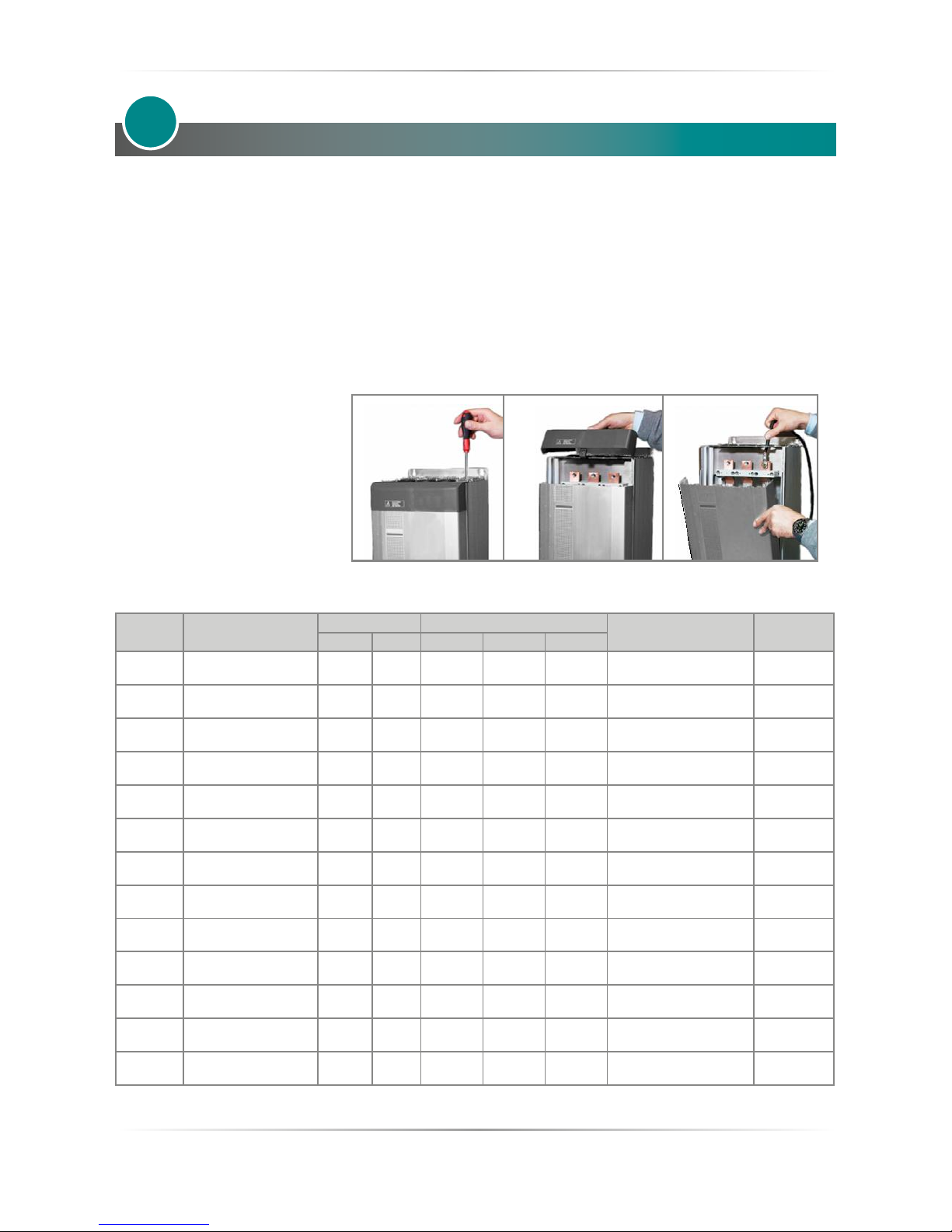
5.1 Removing the cover
Instructions for open the thyristor unit
5
5.2 Line power and Load cable/bar dimensions and torque (suggested)
Current Connector Type
Torque Cable
Cable Terminal
Bar
Lb-in Nm AWG mm
2
kcmil
60A (S11) Terminal Block M8 177 20.0 5 16 33.1
UL Listed (ZMVV)
Copper Tube Crimp. Lug
-
90A (S11) Terminal Block M8 177 20.0 3 25 52.6
UL Listed (ZMVV)
Copper Tube Crimp. Lug
-
120A (S13) Terminal Block M8 177 20.0 2 35 66.4
UL Listed (ZMVV)
Copper Tube Crimp. Lug
-
150A (S13) Terminal Block M8 177 20.0 0 50 106
UL Listed (ZMVV)
Copper Tube Crimp. Lug
-
180A (S13) Terminal Block M8 177 20.0 00 70 133
UL Listed (ZMVV)
Copper Tube Crimp. Lug
-
210A (S13) Terminal Block M8 177 20.0 000 90 168
UL Listed (ZMVV)
Copper Tube Crimp. Lug
-
300A (S14)
Power eld wiring Bus
Bar with M10 screw
265 30.0 2 x 1/0 2 x 70 350
UL Listed (ZMVV)
Copper Tube Crimp. Lug
Bus bar
30x6mm
400A (S14)
Power eld wiring Bus
Bar with M10 screw
265 30.0 2 x 3/0 2 x 95 600
UL Listed (ZMVV)
Copper Tube Crimp. Lug
Bus bar
30x6mm
450A (S14)
Power eld wiring Bus
Bar with M10 screw
265 30.0 2 x 4/0 2 x 95 700
UL Listed (ZMVV)
Copper Tube Crimp. Lug
Bus bar
30x6mm
500A (S14)
Power eld wiring Bus
Bar with M10 screw
265 30.0 - 2 x 150
2x250
900
UL Listed (ZMVV)
Copper Tube Crimp. Lug
Bus bar
60x4mm
600A (S14)
Power eld wiring Bus
Bar with M10 screw
265 30.0 - 2 x 185
2x350
1500
UL Listed (ZMVV)
Copper Tube Crimp. Lug
Bus bar
60x5mm
700A (S14)
Power eld wiring Bus
Bar with M10 screw
265 30.0 - 2 x 300 2x500
UL Listed (ZMVV)
Copper Tube Crimp. Lug
Bus bar
60x6mm
800A (S16)
Power eld wiring Bus
Bar with M10 screw
265 30.0 - 2 x 300 2x500
UL Listed (ZMVV)
Copper Tube Crimp. Lug
Bus bar
60x6mm
Page 19
REVO S 2PH from 60A to 800A - 690V User’s manual
19
5.3 Cable dimensions (suggested) of Earth and of the Command Terminals
Current
Earth Command Terminals
Cable Screw Cable
mm² AWG M mm² AWG
60A (S11) 16 6 M8 0,50 18
90A (S11) 16 6 M8 0,50 18
120A (S13) 16 6 M8 0,50 18
150A (S13) 25 4 M8 0,50 18
180A (S13) 25 4 M8 0,50 18
210A (S13) 25 4 M8 0,50 18
300A (S14) 50 1 M8 0,50 18
400A (S14) 50 1 M8 0,50 18
450A (S14) 70 1/0 M8 0,50 18
500A (S14) 70 1/0 M8 0,50 18
600A (S14) 70 1/0 M8 0,50 18
700A (S14) 70 1/0 M8 0,50 18
800A (S16) 70 1/0 M8 0,50 18
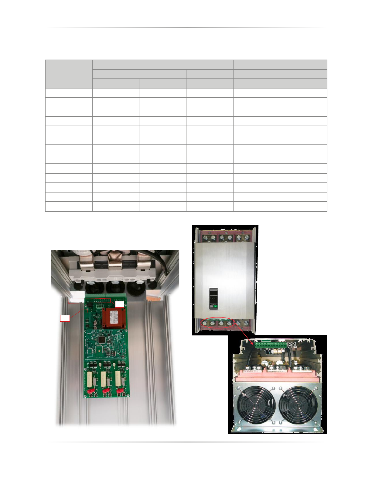
5.4 Terminals Positions
Open and ip the cover
M1
M2
Page 20
20
REVO S 2PH from 60A to 800A - 690V User’s manual
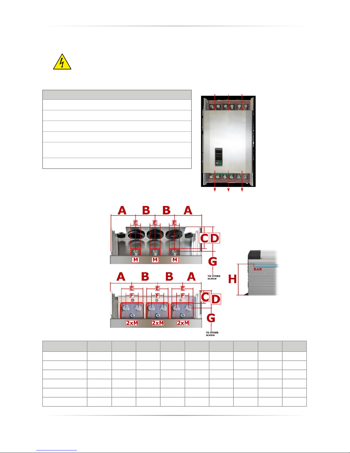
5.5 Power Terminals
Warning: Before connecting or disconnecting the unit check that power and control cables
are isolated from voltage sources.
Terminal Description
L1 Line Input Phase 1
L2 Line Input Phase 2 (Only S14)
L3 Line Input Phase 3
T1 Load Output Phase 1
T2
Load Output Phase 2 -
Not controlled by the thyristor (only S14)
T3 Load Output Phase 3
5.5.1 Bar dimensions S14
Current
A B C D E F G H M
300A (S14) 71mm 60mm 45mm 57mm 30mm - 350mm 174mm M10
400A (S14) 71mm 60mm 45mm 57mm 30mm - 350mm 174mm M10
450A (S14) 71mm 60mm 45mm 57mm 30mm - 350mm 174mm M10
500A (S14) 71mm 60mm 45mm 57mm 30mm - 350mm 174mm M10
600A (S14) 54mm 76mm 21mm 37mm 66mm 35mm 390mm 165mm M10
700A (S14) 54mm 76mm 21mm 37mm 66mm 35mm 390mm 165mm M10
2PH from 300 to 500A
2PH from 600 to 700A
L1 L2 L3
T1 T2 T3
REVO-S 2PH
300A÷700A (S14)
Page 21
REVO S 2PH from 60A to 800A - 690V User’s manual
21
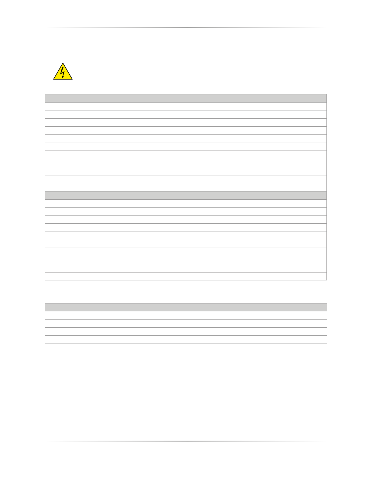
5.6 Control Terminals
Warning: Before connecting or disconnecting the unit check that power and control cables
are isolated from voltage sources.
M1
Terminal Description
1 NO - Normally Open contact alarm relay output (HB)
2 C - Common contact alarm relay output
3 NC - Normally Close contact alarm relay output (HB)
4 Not Connected
5 DI 2 – Enable Digital Input
6 DI 1 - Congurable Input
7 Not Connected
8 Not Connected
9 Output +10Vdc stabilized 1 mA MAX
10 0V GND
Terminal Description
11 - Analog Input 1 (0-10Vdc/4-20mA Analog Setpoint)
12 + Analog Input 1 (0-10Vdc/4-20mA Analog Setpoint)
13 COM I - Common Digital Input
14 Not Connected
15 Fan supply (230V Standard – 115 Option - for DC Fan Option +24Vdc)
16 Fan supply (230V Standard – 115 Option - for DC Fan Option -24Vdc)
17 Not Connected
18 Aux – Voltage Supply for electronic boards and synchronization (See order code for the Value)
19 Not Connected
20 Aux – Voltage Supply for electronic boards and synchronization (See order code for the Value)
M2
Terminal Description
1 24V Out Max 5mA
2 Slave Output
3 Not Connected
4 0V GND
Page 22
22
REVO S 2PH from 60A to 800A - 690V User’s manual
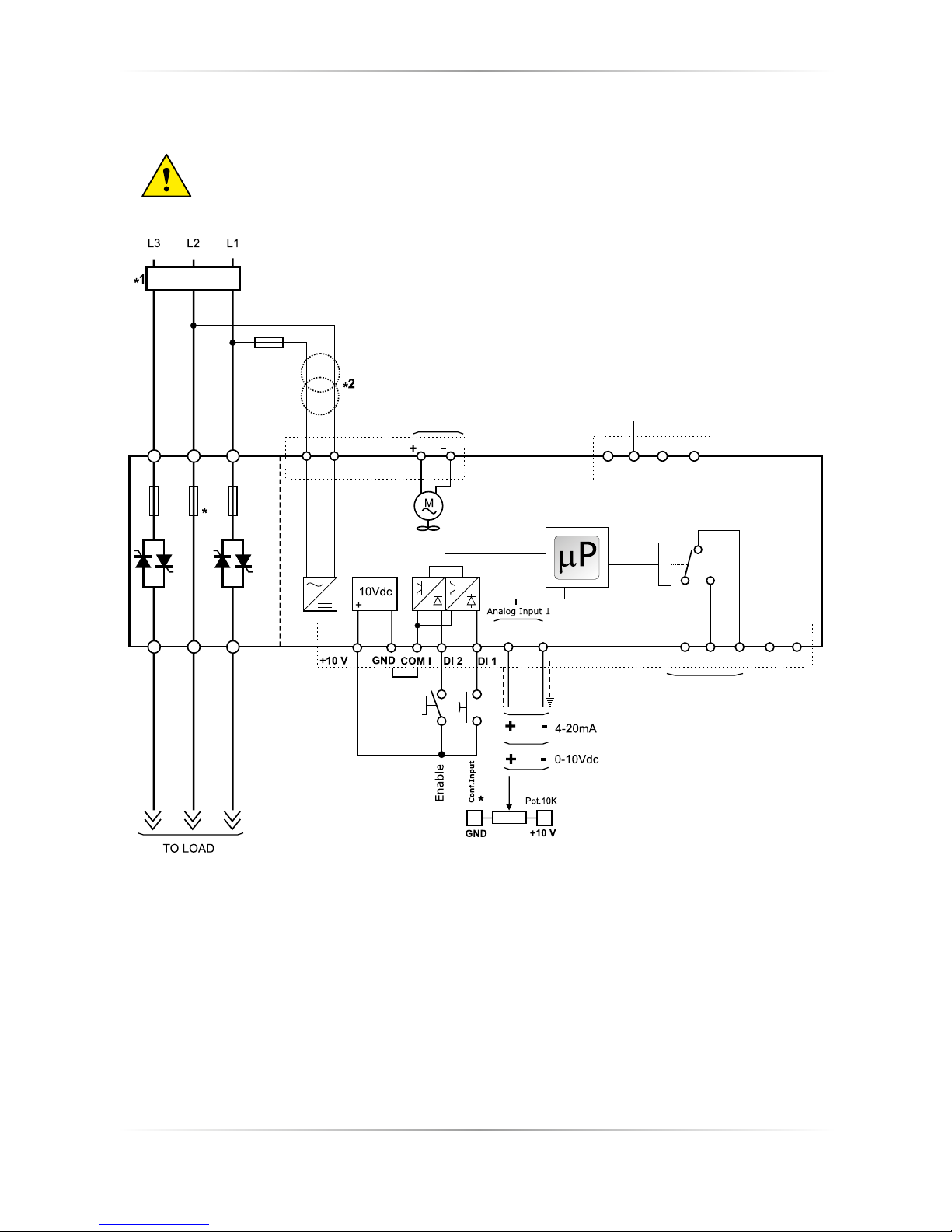
5.7 Schematic
Caution: this procedure must be performed only by qualied persons.
NOTE:
*
1 The user installation must be protecting by electromagnetic circuit breaker or by fuse isolator.
The Fuse must be branch circuit protection.
*
2 The auxiliary voltage supply of the Revo C unit must be synchronized with load voltage power supply. If the
Auxiliary Voltage (written on the identication label) is dierent from Supply Voltage (to the load), use an
external transformer as designated.
*
3 On phase L2 fuse not available for size 600-700A
*
4 For SSR input connection follow next page schematic.
M1
M1
M2
L3 L2 L1 18 15 1620
AUX AUX
T3 T2 T1
SLAVE
OUT
3 4
9 10 13 5 6 12 11 3 1 2 8
NC NO C
7
+24V GND
21
4
10
9
3
Function
Thermal
SC/HB
Fan supply
230Vac Standard
115Vac option
24Vdc option
See Order Code
Analog Inp.1
Analog SetPoint
Fuse
5A Max
Branch Circuit
Protection
Not connected
Page 23
REVO S 2PH from 60A to 800A - 690V User’s manual
23
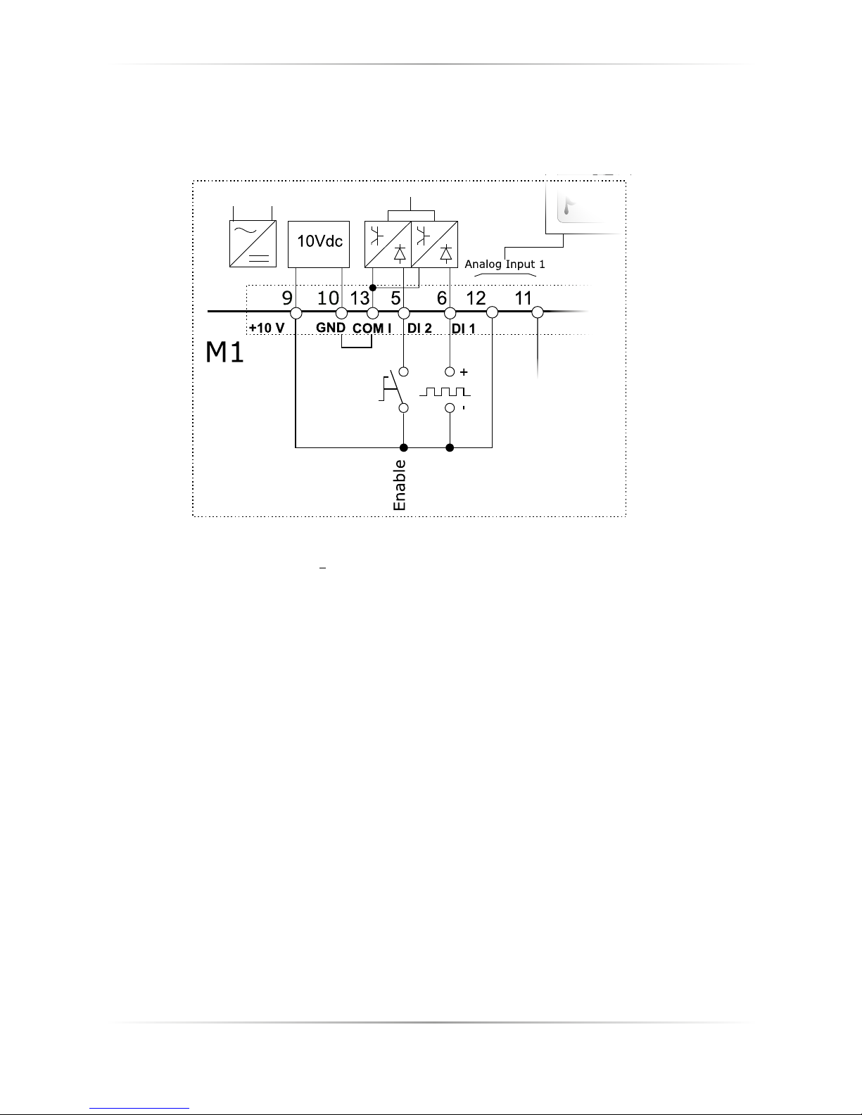
5.7.1 SSR Control Input schematic
For SSR input use follow the schematic below and congure Digital Input 1 as Fast Enable.
SSR
INPUT
* SSR Input:
4 ÷ 30Vdc 5mA Max (ON >4Vdc OFF <1Vdc)
3HZ Max on time min. 100 ms
Page 24
24
REVO S 2PH from 60A to 800A - 690V User’s manual
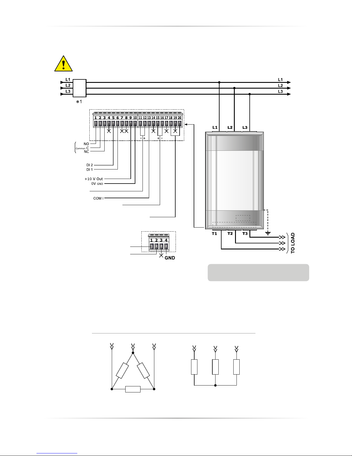
Note: Aux Voltage and Load Voltage
must be synchronized
5.8 Connection Diagram for 3 phases (control on 2 phases)
Caution: this procedure must be performed only by qualied persons.
X = not connected
*
1 The user installation must be protecting by electromagnetic circuit breaker or by fuse isolator.
The Fuse must be branch circuit protection. For UL any listed UL branch circuit fuse would be acceptable
as an external fuse, following national electric code guide for resistive heating of 125% load current rating to
protect external wires.
M2
M1
M2
M1
+24V
SLAVE OUT
Analog Inp.1
0-10VDC /4-20mA
ANALOG SET POINT
Branch
Circuit
Protection
Relay
Thermal or
SC/HB
Fan Power Supply
See order code for the value
AUX Voltage Supply
See order code for the value
Load Type
Delta Star
T1 T2 T3
T1 T2 T3
Page 25
REVO S 2PH from 60A to 800A - 690V User’s manual
25
Led status and alarms
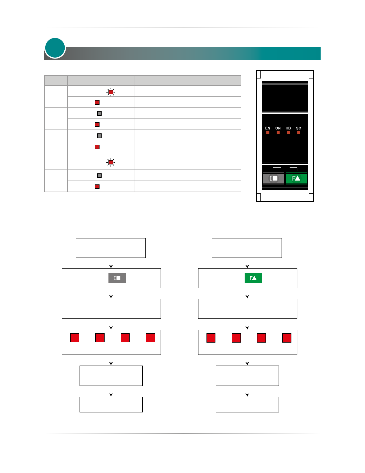
LED status
LED STATUS DESCRIPTION
EN
LED Flashing ( )
Waiting for Enable Signal
LED ON ( ) Enable Signal to terminal
ON
LED OFF ( ) Load is NOT powered
LED ON ( ) Load is powered
SC
LED OFF ( ) Load OK
LED ON ( ) SCR short circuit (only with HB option)
LED Flashing ( )
Enable contact open or
Over temperature on heat sink
HB
LED OFF ( ) Load OK
LED ON ( ) Load Fault (only with HB option)
6
CAL
BF 2 BF 4 BF 8 BF 16
Keep pressed for 2 sec
Wait more than 10 seconds
after power on
The LEDs turn o for 2 seconds
and the setting is displayed
END
The LEDs turn o
for 4 seconds
0-10V 4-20mA 0-20mA SSR
Keep pressed for 2 sec
Wait more than 10 seconds
after power on
The LEDs turn o for 2 seconds
and the setting is displayed
END
The LEDs turn o
for 4 seconds
Input type informations Burst Firing informations
Page 26
26
REVO S 2PH from 60A to 800A - 690V User’s manual
Heater Break alarm and SCR short circuit
(HB Option only)
Caution: to work properly the load must be powered at least about 160msec.
The Heater Break circuit read the load current with an Internal current transformer (C.T.).
Minimum current is 10% of the current transformer size.
If load current is below this value the Heater Break Alarm doesn’t work properly.
7.1 Heater break Calibration procedure
An automatic function sets the Heater Break Alarm.
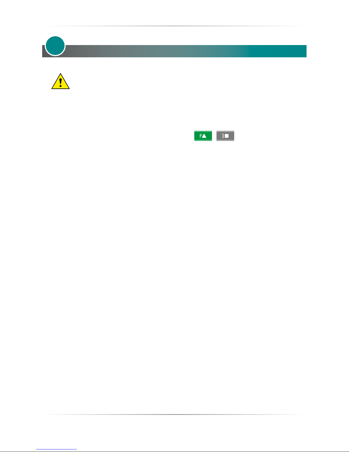
The auto setting function can be activated by pressing the keys + simultaneously for 4 seconds.
The Heater Break calibration procedure is performed in this way:
• The Unit gives the maximum voltage output
• The leds light up in sequence until the procedure is completed
• The current and voltage value is stored in memory
• After about 15 second the unit comes back to the initial situation
If load resistance increase more than 20% (sensitivity 20%) the HB LED become ON and alarm relay change
status.
If the unit is still in conduction with no input signal (ON LED OFF) it means that there is a short circuit on
thyristors and SC LED become ON.
If the load has been changed the Heater Break calibration procedure must be done again.
The HB Alarm is detected with minimum ON time 100 ms
7
Page 27
REVO S 2PH from 60A to 800A - 690V User’s manual
27
Input Setting
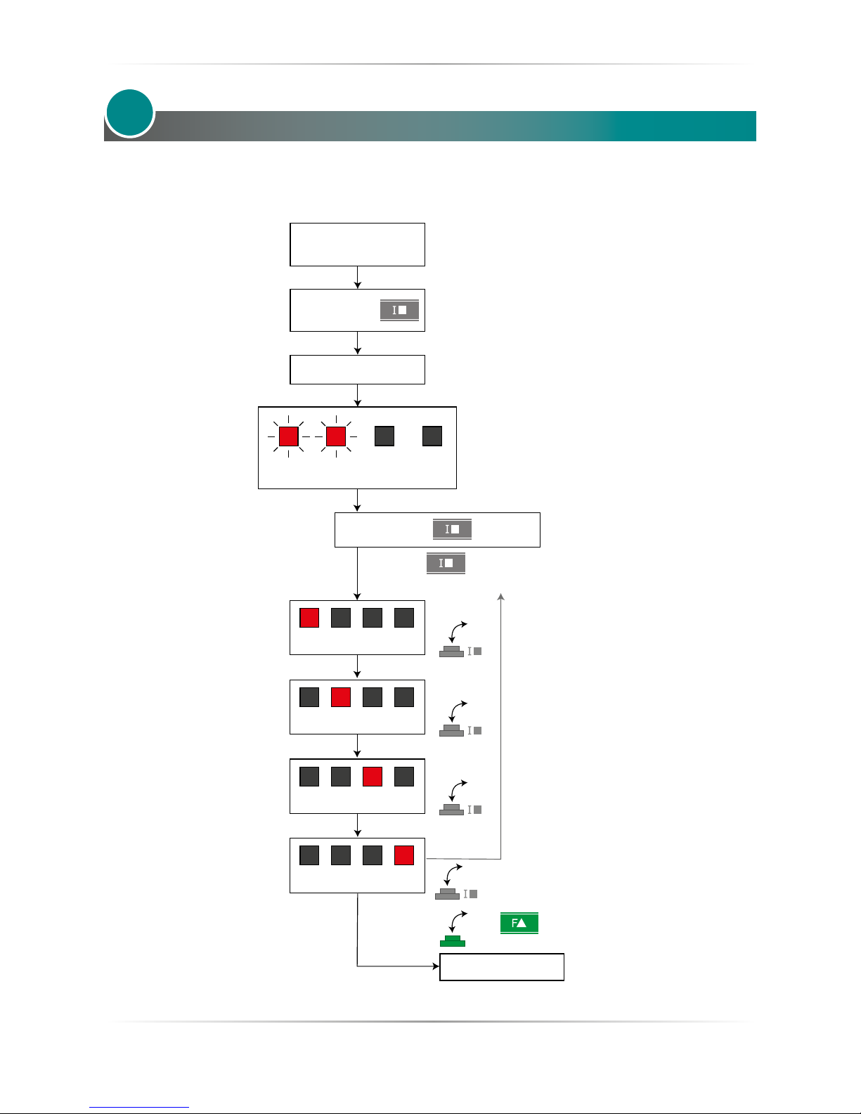
The Input type is already congured in line with customer requirements that are dened in the order code.
However, if you need to to make changes you must follow the following procedure.
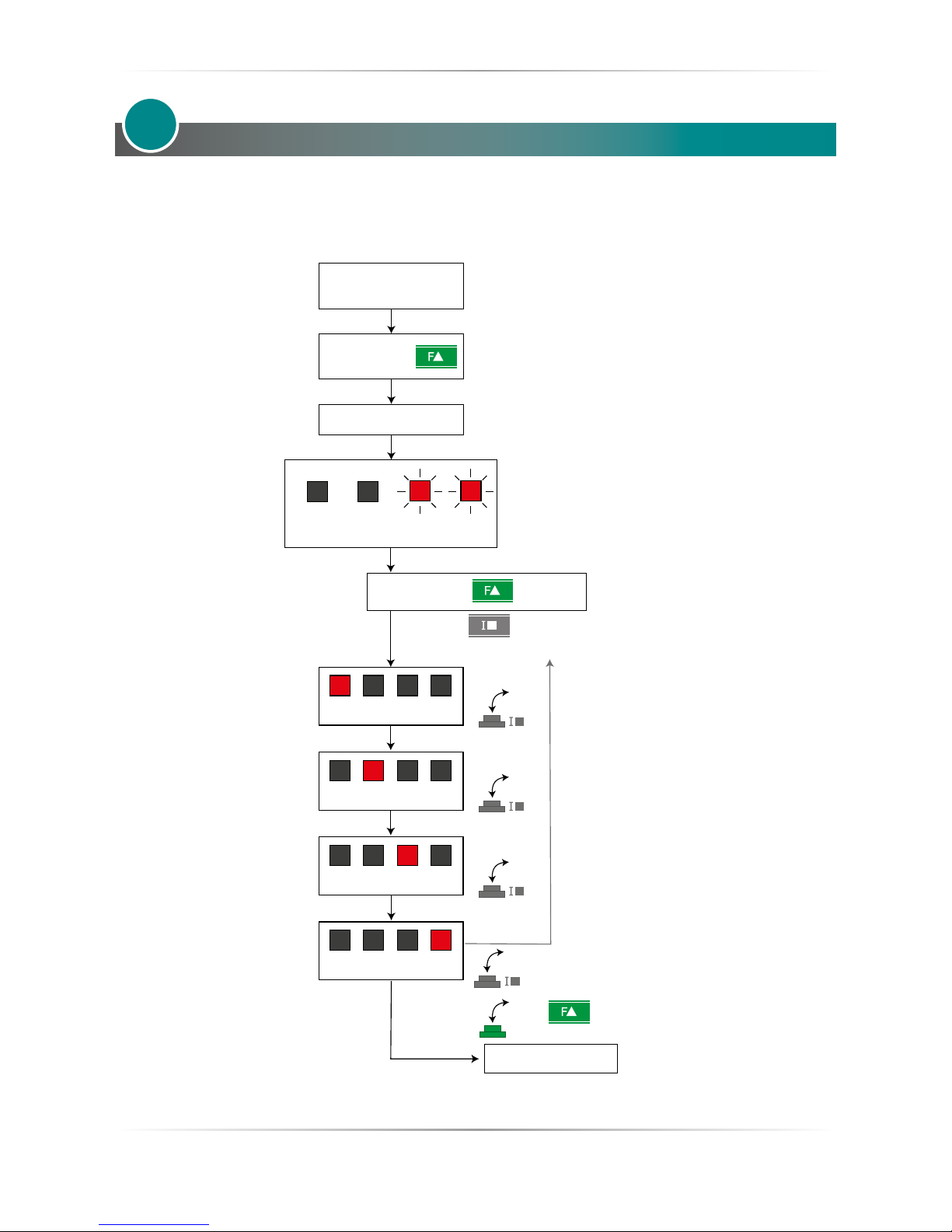
8
0-10V
4-20mA
0-20mA
SSR
Keep pressed
Release
Remove
auxiliary power supply
Supply the Unit
LED1 - LED2 ashing for 3 sec.
END
Press to save
the conguration
Press to choose
the desired conguration
Page 28
28
REVO S 2PH from 60A to 800A - 690V User’s manual
Burst Firing settings
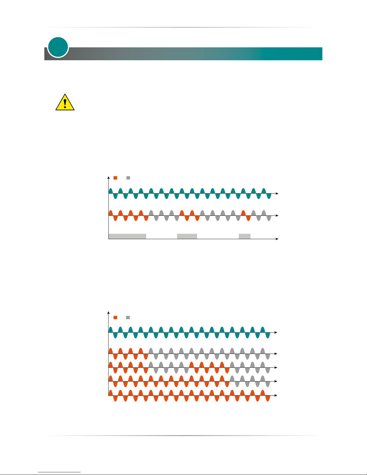
The Burst Firing cycles is already congured in line with customer requirements that are dened in the Order
Code. However, if you wish to change the Burst Firing cycles (es. from 4 to 8) you must follow the following
procedure.
9
BF 2
BF 4
BF 8
BF 16
Keep pressed
Release
Remove
auxiliary power supply
Supply the Unit
LED3 - LED4 ashing for 3 sec.
Press to save
the conguration
Press to choose
the desired conguration
END
Page 29
REVO S 2PH from 60A to 800A - 690V User’s manual
29
Firing type
Choose a correct ring type allows to optimize the thyristor unit for the installed load.
The ring type has already congured in line with customer requirements, Zero Crossing for SSR input and
Burst ring for Analog Input.
Caution: this procedure must be performed only by qualied persons.
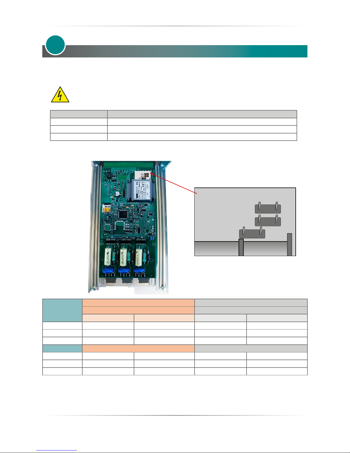
10.1 Zero Crossing
ZC ring mode is used with Logic Output from temperature controllers and the Thyristor operates like a
contactor.
The Cycle time is performed by temperature controller. ZC minimizes interferences because the Thyristor unit
switches ON-OFF at zero voltage.
10.2 Burst Firing
The Burst Firing is similar to the Single Cycle, but consecutive cycles ON are selectable between 1 and 255,
with input signal equal at 50%. When is specied 1 the ring type is Single Cycle.
Burst Firing is a method zero crossing that it reduces the electromagnetic interferences because the thyristor
switches at zero voltage crossing.
The example show the Burst Firing with Burst cycles=4.
10
ON OFF
Voltage Supply (V)
Load Voltage (V)
SSR from controller
25%
50%
75%
100%
ON OFF
Voltage Supply (V)
Load Voltage (V)
Page 30
30
REVO S 2PH from 60A to 800A - 690V User’s manual
Supply the electronic board
The REVO S thyristor unit, to work, requires a voltage supply for the electronic boards. The Max consumption is 8VA.
The voltage supply for the electronic boards is congured in line with customer requirements that are dened
in the Order Code. The Order Code is written on the identication label.
Warning: Before connecting or disconnecting the unit check that power and control cables
are isolated from voltage sources.
Terminal M1 Description
18 Voltage Supply for Electronic Boards (Auxiliary Voltage)
19 Not Used
20 Voltage Supply for Electronic Boards (Auxiliary Voltage)
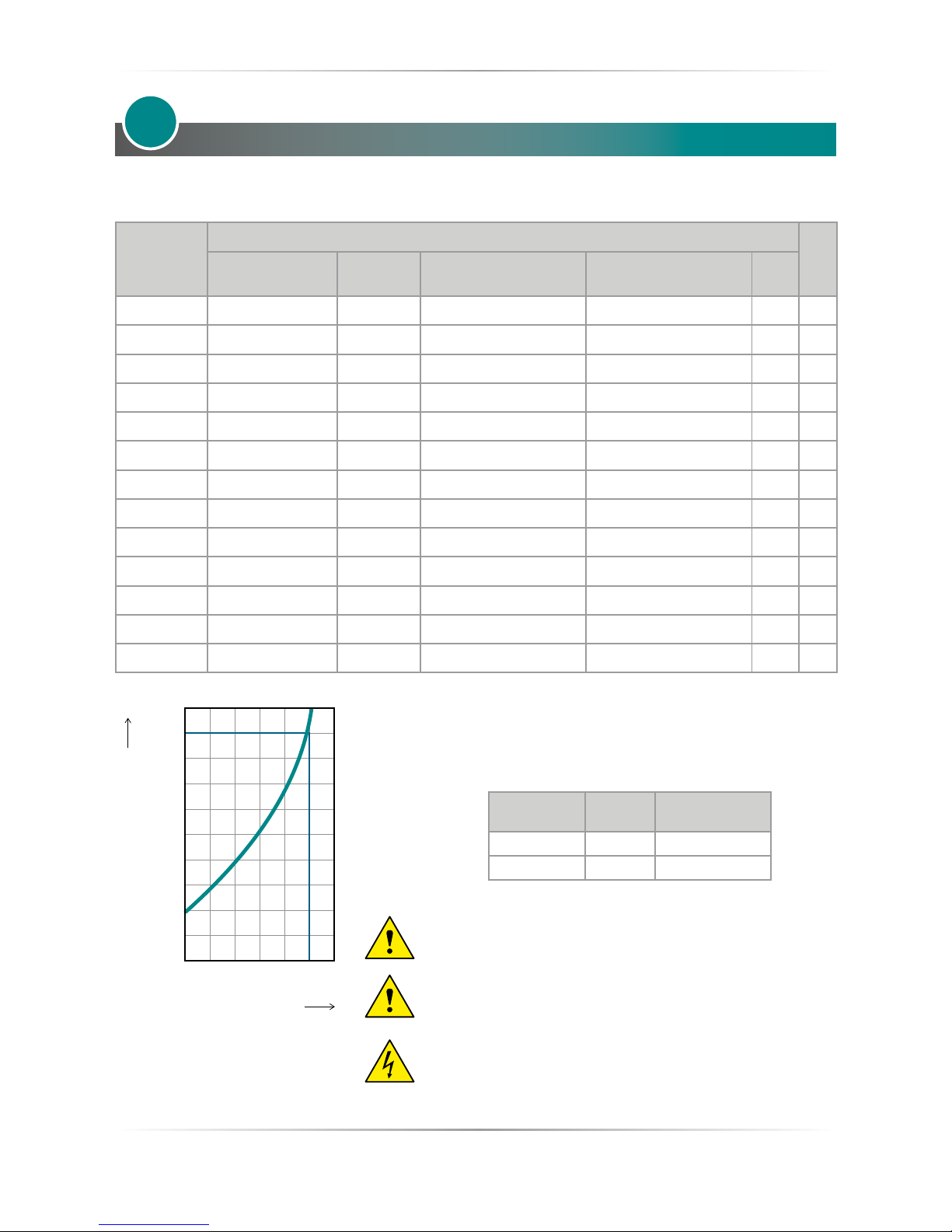
To change auxiliary supply voltage sold the correct link-jumper on REVO S board, the type of mounted
transformer depends of the chosen Voltage in the order code.
11
Order Code
As ordered Change to
Jumper JP1 + JP2 are linked Link only Jumper JP3
Transformer range Line voltage Transformer range Line voltage
RS2_ _ _-_1 90:135V 100/120V 180:265V 200/208/220/230/240
RS2_ _ _-_2 180:265V 200/208/220/230/240V 342:528V 380/400/415/440/480
RS2_ _ _-_3 238:330V 277V 540:759V 600/690
Only Jumper JP3 is linked Link Jumper JP1 + JP2
RS2_ _ _-_5 342:528V 380/400/415/440/480V 180:265V 200/208/220/230/240V
RS2_ _ _-_6 540:759V 600V 238:330V 277V
RS2_ _ _-_7 540:759V 690V 238:330V 277V
If the Auxiliary Voltage (written on the identication label) is dierent from Supply Voltage (to the load), use an
external transformer with primary equal to load voltage and secondary equal to the Auxiliary Voltage.
Attention! never link all the jumpers JP1+JP2+JP3 at the same time or JP3 + any other jumper, JP3 must be
always alone, follow only the conguration shown.
JP1
JP2
JP3
Page 31
REVO S 2PH from 60A to 800A - 690V User’s manual
31
Internal Fuse
The thyristor unit have internal fuse extrarapid at low I²t for the thyristor protection of against the short-circuits.
The Fuses must have I²t 20% less than thyristor’s I²t. The warranty of thyristor is null if no proper fuses are used.
Size
200 kARMS Symmetrical A.I.C.
Qty
Fuse CODE
Current
(ARMS)
FUSE I2T value
Suggested A2s (at500V)*
FUSE I2T value
Suggested A2s (at660V)
Vac
60A (S11) 20 282 20.160 160 15400 16940 690 3
90A (S11) 20 282 20.160 160 15400 16940 690 3
120A (S13) 20 282 20.160 160 15400 16940 690 3
150A (S13) 20 282 20.200 200 25000 27500 690 3
180A (S13) 20 282 20.250 250 44000 48400 690 3
210A (S13) 20 282 20.315 315 77000 84700 690 3
300A (S14) FMM400 400 72500 79750 690 3
400A (S14) FMM550 550 215000 236500 690 3
450A (S14) 2x FM315 2 x 315 308000 338800 690 3
500A (S14) 2x FM315 2 x 315 308000 338800 690 3
600A (S14) 2x FMM450 2 x 450 420000 462000 690 2
700A (S14) 2x FMM450 2 x 450 420000 462000 690 2
800A (S16) 4x 20 559 20.250 4 x 250 352000 387200 690 2
*I2T are multiplied for K value in function of Vac at 690V K is equal
to 1,1 (ex:15400 X 1,1 = 16940). At 660Vac K is equal to 1
Fuses replacement: Open the cover and remove the screws,
then replace it with the correct fuse, use the screws with a proper
suggested torque indicated below
TYPE Screw
Torque Lb-in
(N-m)
60A-210A M6 44.2 (5.0)
300A-800A M8 133.7(15.0)
Caution: High speed fuses are used only for the thyristor
protection and can not be used to protect the installation.
Caution: The warranty of thyristor is null if no proper fuses
are used. See tab.
Warning: When it is supply, the Thyristor unit is subject to
dangerous voltage, don’t open the Fuse-holder module and
don’t touch the electric equipments.
12
1.2
1.0
0.8
0.6
0.4
0.2
200 400 600 800
1.1
690
Vac
K
(Line voltage)
Page 32

CD Automation S.r.l.
Via Picasso, 34/36 - 20025 Legnano (MI)- Italy
Tel. +39 0331 577479 - Fax +39 0331 579479
E-mail: [email protected] - Web: www.cdautomation.com
 Loading...