

Page 1
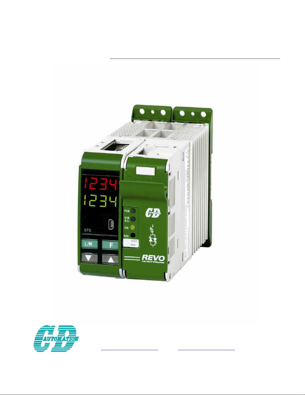
USER’S MANUAL
Rev. 06/2009
Revo
M
from 30A to 45A
CD Automation S.r.l.
Via Picasso 34/36 - 20025 – Legnano (MI) – ITALY
Tel +39 0331 577479 – Fax +39 0331 579479
E-Mail: [email protected] - WEB: www.cdautomation.com
Page 2

CD Automation srl REVO M User’s Manual
REVO_M08
2
Page 3

CD Automation srl REVO M User’s Manual
1 IMPORTANT WARNINGS FOR SAFETY __________________________________________5
2 NOTE ___________________________________________________________________6
3 INTRODUCTION ___________________________________________________________7
4 ADVANTAGES COMPARED WITH ANALOG THYRISTOR UNIT _________________________7
5 SOFTWARE CONFIGURATOR CDA THYRISTOR CONFIGURATOR SOFTWARE _____________8
6 QUICK START _____________________________________________________________9
7 BASIC CONNECTIONS AND SIZING ___________________________________________10
8 IDENTIFICATION AND ORDER CODE __________________________________________11
8.1 Identification of the unit ______________________________________________________11
8.2 Order Code ________________________________________________________________12
9 INTERNAL FUSE __________________________________________________________13
9.1 Fuses Replacement __________________________________________________________13
10 INSTALLATION __________________________________________________________14
10.1 Environmental installation conditions ___________________________________________14
10.2 Derating Curve ____________________________________________________________14
10.3 Dimensions and Weight _____________________________________________________15
10.4 Fixing holes _______________________________________________________________15
10.5 Technical Specifications _____________________________________________________16
11 WIRING INSTRUCTIONS __________________________________________________17
11.1 Command Terminals ________________________________________________________18
11.1.1 Terminal block M2 Drive M_________________________________________________________________ 18
11.1.2 Terminal block M1 Drive M_________________________________________________________________ 18
11.1.3 Terminal block M3 Drive M_________________________________________________________________ 18
11.1.4 Terminal block M4 Drive M_________________________________________________________________ 18
11.2 Schematic ________________________________________________________________19
11.3 Connection Diagram for Single-phase___________________________________________20
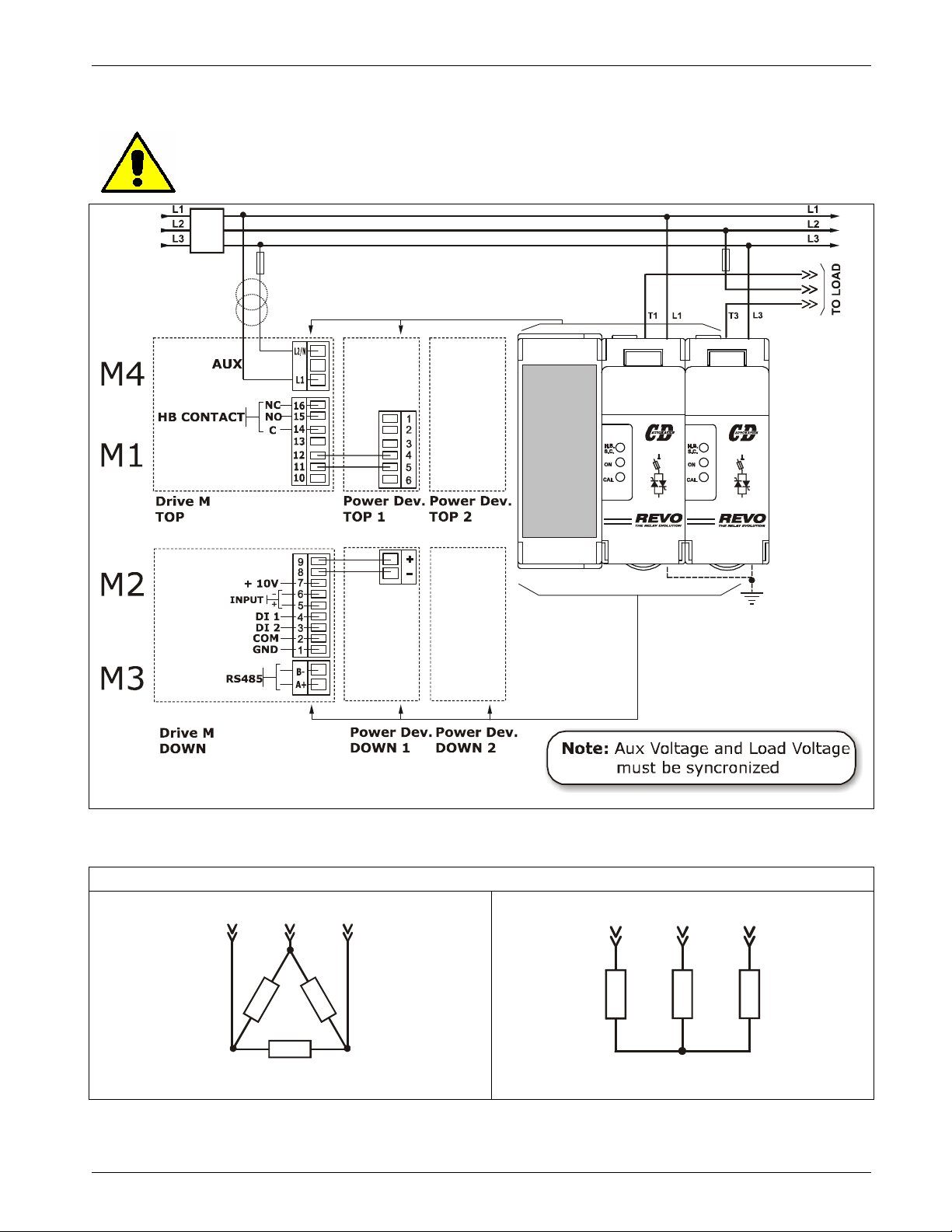
11.4 Connection Diagram for 3 phases (control on 2 phases) ____________________________21
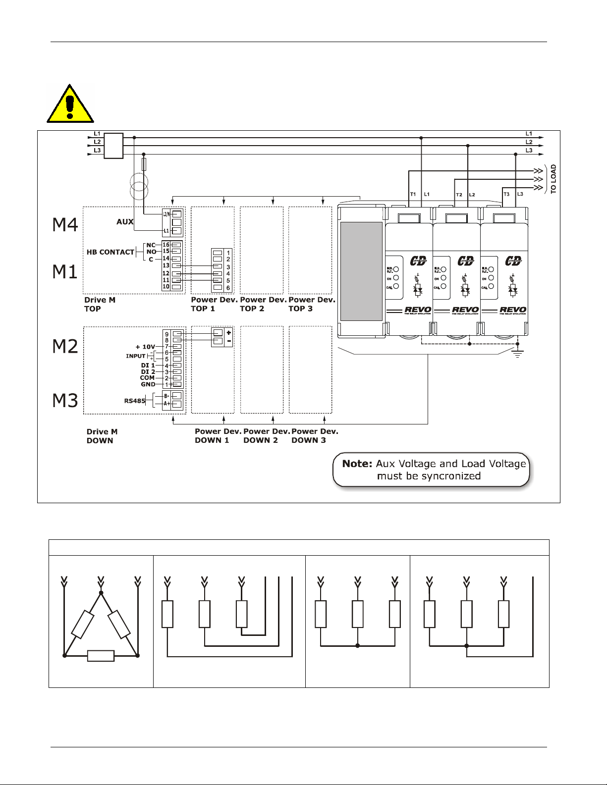
11.5 Connection Diagram for 3 phases (control on 3 phases) ____________________________22
12 CONTROL PANEL_________________________________________________________23
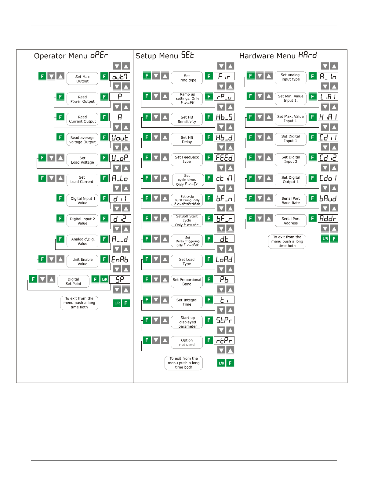
12.1 Scroll the parameters _______________________________________________________24
13 INPUT OUTPUT SIGNAL ___________________________________________________25
13.1 Digital Input ______________________________________________________________25
13.1.1 Start/Stop (Terminal 3 of M2) ______________________________________________________________ 25
13.1.2 Configurable Input (Terminal 4 of M2) ________________________________________________________ 25
13.2 Digital Output terminal (terminal 14-15-16 of M1)_________________________________25
13.3 Analog Input ______________________________________________________________25
Primary Input (Terminals 5 and 6 of M2) ___________________________________________________________ 25
14 HEATER BREAK ALARM AND SCR SHORT CIRCUIT (HB OPTION) ____________________26
14.1 Heater break Calibration procedure ____________________________________________26
14.2 HB alarm contact (digital output) ______________________________________________26
15 FIRING TYPE ___________________________________________________________27
REVO_M08
3
Page 4

CD Automation srl REVO M User’s Manual
15.1 Single Cycle SC (1Ph Only) __________________________________________________ 27
15.2 Burst Firing (BF) __________________________________________________________ 28
15.3 Soft Start with Burst Firing S+BF (1Ph Only) ____________________________________ 28
15.4 Phase Angle PA (1Ph Only) __________________________________________________ 29
15.5 Soft Start with Phase Angle (S+PA) ___________________________________________ 29
15.6 Delay Triggering DT (1Ph Only) _______________________________________________ 30
16 FEED-BACK TYPE________________________________________________________ 31
17 ELECTRONIC BOARDS ____________________________________________________ 32
17.1 How to access ____________________________________________________________ 32
17.2 Supply the Electronic Board__________________________________________________ 33
17.3 Analog Inputs ____________________________________________________________ 34
17.3.1 Primary Input (Terminals 5 and 6 of M2) ______________________________________________________34
18 PG CONNECTOR ________________________________________________________ 35
19 RS485 SERIAL PORT _____________________________________________________ 36
20 MODBUS COMMUNICATION _______________________________________________ 37
20.1 MODBUS RTU Protocol ______________________________________________________ 37
20.2 Message Format___________________________________________________________ 37
20.3 Read Holding Registers _____________________________________________________ 39
20.4 Preset Multiple Registers ____________________________________________________ 39
20.5 Error and exception responses _______________________________________________ 40
20.6 Address Configuration ______________________________________________________ 40
21 CONFIGURATION PARAMETERS ____________________________________________ 41
22 MAINTENANCE _________________________________________________________ 47
22.1 Trouble Shooting __________________________________________________________ 47
22.2 Warranty condition ________________________________________________________ 47
REVO_M08
4
Page 5
CD Automation srl REVO M User’s Manual
1 Important warnings for safety
This chapter contains important information for the safety. The not observance of these instructions may
result in serious personal injury or death and can cause serious damages to the Thyristor unit and to the
components system included.
The installation should be performed by qualified persons.
The Thyristor unit are integral part of industrial equipments. When it is supply, the
Thyristor unit is subject to dangerous tensions.
• Don't remove the protection Cover.
• Don't use these unit in aerospace applications and/ or nuclear.
The nominal current corresponds to use at temperature not superior to 45°C.
• The Thyristor unit must be mounted in vertical position and without obstruction above
and below to allow a good flow ventilation.
• The hot air of one thyristor unit must not invest the unit positioned above.
• For side by side placed leave a space of 15mm between the unit.
A suitable device must ensure that the unit can be electrically isolated from the supply, this
allows the qualified people to work in safety.
Protection (Protection, Protezione)
The unit have IP20 protection rating as defined by the specific international. Is necessary
consider the place of installation.
Earth (Terre, Messa a terra)
For safety, the Thyristor unit with isolated heat-sink must be connected to earth.
Earth impedance should be correspondent to local earth regulation. Periodically the earth
efficiency should be inspected.
Electronic supply (Alimentation électronique, Alimentazione elettronica)
The electronic circuit of the Thyristor unit must be supplied by dedicated voltage for all
electronic circuits and not in parallel with coil contactors, solenoids and other.
It's recommended to use a shielded transformer.
Electric Shock Hazard (Risque de choque électrique, Rischi di scosse elettriche)
When the Thyristor unit is energized, after the power supply is shut off, wait least a minute
for allow the discharge of the internal capacitors where there is a dangerous tension. Before
working, make sure that:
• Only authorized personnel must perform maintenance, inspection, and replacement
operations.
• The authorized personnel must read this manual before to have access to the unit.
• Unqualified People don't perform jobs on the same unit or in the immediate vicinities.
REVO_M08
5
Page 6
CD Automation srl REVO M User’s Manual
Important warnings (Attention, Avvertenze importanti)
During the operations with units under tension, local regulations regarding electrical
installation should be rigidly observed:
• Respect the internal safety rules.
• Don't bend components to maintain insulation distances.
• Protect the units from high temperature humidity and vibrations.
• Don't touch components to prevent electrostatic discharges on them.
• Verify that the size is in line with real needs.
• To measure voltage current etc. on unit, remove rings and other jewels from fingers
and hands.
• Authorized personnel that work on thyristor unit under power supply voltage must be
on insulated board
This listing does not represent a complete enumeration of all necessary safety cautions.
Electromagnetic compatibility
(Compatibilità électromagnétique, Compatibilità elettromagnetica)
Our thyristor units have an excellent immunity to electromagnetic interferences if all
suggestions contained in this manual are respected. In respect to a good Engineering
practice, all inductive loads like solenoids contactor coils should have a filter in parallel.
2 Note
Emissions (Emission, Emissioni)
All solid-state power controllers emit a certain amount of radio-frequency energy because
of the fast switching of the power devices.
The CD Automation’s Thyristor unit are in accord with the EMC norms, CE mark.
In most installations, near by electronic systems will experience no difficulty with
interference. If very sensitive electronic measuring equipment or low-frequency radio
receivers are to be used near the unit, some special precautions may be required. These
may include the installation of a line supply filter and the use of screened (shielded) output
cable to the load.
Warning: This icon is present in all the operational procedures where the Improper
operation may result in serious personal injury or death
Caution: This icon is present in all the operational procedures where the Improper
operation can cause damage for the Thyristor unit.
CD Automation reserves the right to modify the own products and this manual without any
advise.
REVO_M08
6
Page 7
CD Automation srl REVO M User’s Manual
3 Introduction
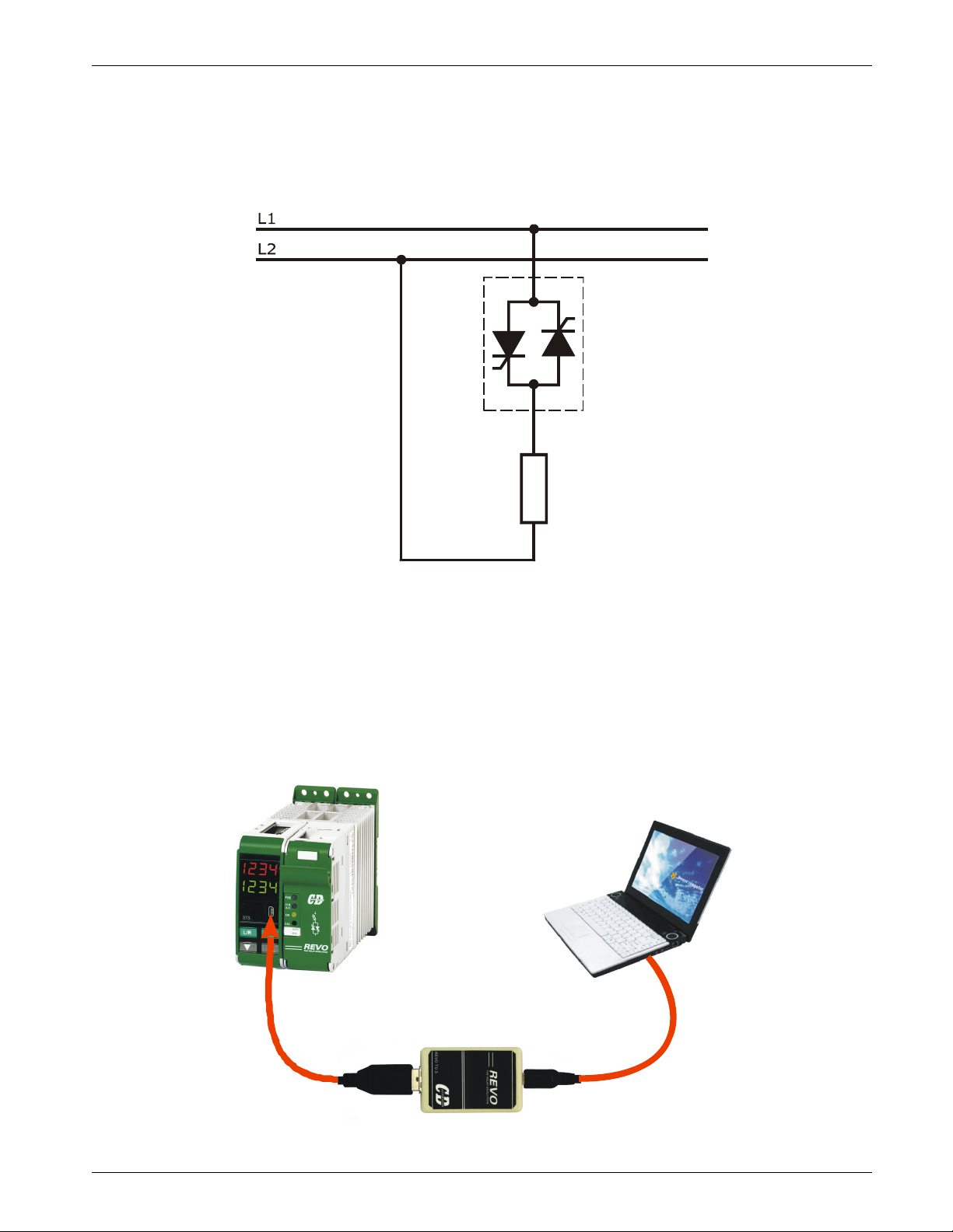
A thyristor unit is semiconductor device which acts as a switch formed by two thyristors in ant parallel.
To switch on the alternating current the input signal will be on and the thyristor will switch off at first
Zero Crossing voltage with no input signal.
The benefits of thyristor units compared with elettromechanical contactors are numerouses: no moving
parts, no maintenance and capacity to switch very fast. Thyristors are the only solution to control
transformers and special loads that change resistance with temperature and with age.
Thyristor
Load
4 Advantages compared with analog thyristor unit
Communication RS485 is a standard feature of REVO M this allows the use of many information like:
current, power, load state and all the parameters for diagnostic and configuration. Ulterior advantages
of the digital system vs the analogical is the flexibility and the possibility of implement special
characteristics without change the hardware. Several strategies can be implemented and selected
through the configuration parameters.
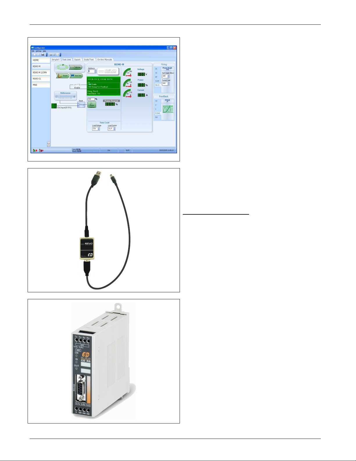
With CDA software configuration, you can have access to the configuration parameters.
To connect the Thyristor unit to the computer use the USB\TTL converter.
REVO_M08
7
Page 8
CD Automation srl REVO M User’s Manual
5 Software Configurator CDA Thyristor configurator software
CDA Thyristor configurator software
is free and is possible download it from our site:
www.cdautomation.com
If the Order Code is in line with requirement,
then REVO M has been already configured in
Factory and it's ready to use.
You need the software only to modify the ordered
configuration. Anyway we suggest to check the
unit on the machine with the "Test unit" section.
For install the software, launch the program and
follow the instructions on the screen.
Run the software configurator and set the serial
port of the PC with con baudrate =19200(default)
and the address of Thyristor unit (default=1).
To connect the unit at the PC, it's necessary use
the USB\TTL converter connected between the
unit and the USB port of the PC.
USB\TTL converter need a driver to work
properly, you can find it at
www.cdautomation.com
Is available a full programmer kit composed by
• USB\TTL converter,
• Two cable
• CDA Thyristor configurator software
• USB driver on CD Rom
Utility\driver USB
REVO_M08
With the CD-RS serial converter is possible
configure the Thyristor unit also through the
RS485 For this solution, the programming cable
is not necessary.
8
Page 9

CD Automation srl REVO M User’s Manual
6 Quick Start
Attention: this procedure must be carried out by skilled people only.
If your REVO M code is in line with what you really need, then the main configuration is already done by
CD Automation and you just need to do the following steps:
1. Verify REVO M’s current sizing. Be sure that:
• the load current is equal or less than the nominal one of REVO M
• the main voltage is equal or less than the nominal voltage of REVO M
2. Verify the Installation
3. Verify the Wiring:
• all auxiliary connections must be done in line with wirings on this manual
• verify that there isn’t a short circuit on the load
4. Supply the auxiliary voltage of the unit
Set the parameters U_OP (Operative Voltage) and A_Lo (Nominal Current of the load) using the
frontal keypad or CDA Thyristor configurator software.
Function: It’s necessary to specify the operative voltage
Min/Max: 24 ÷ 1000V
Default: 230
Note: With voltage up to 330V and over 600V, REVO M needs hardware
Function: It’s necessary to specify the load current value at nominal voltage.
Min/Max: 1 ÷ 100.0 Ampere (for size up to 100A)
Default: Nominal REVO M current value if load current has not been specified.
If your REVO M code is NOT in line with what you really need, use the enclosed configurator
software tool to set-up the unit. Install the software on your PC, select REVO M and click on
test unit changing what you need.
Operative Voltage V R/W
modifications: specify this in phase of ordination.
Load nominal current A R/W
This current and voltage value are necessary to be able to read the
power in engineering units
REVO_M08
9
Page 10
CD Automation srl REVO M User’s Manual
V
I
I
I
I
I
V
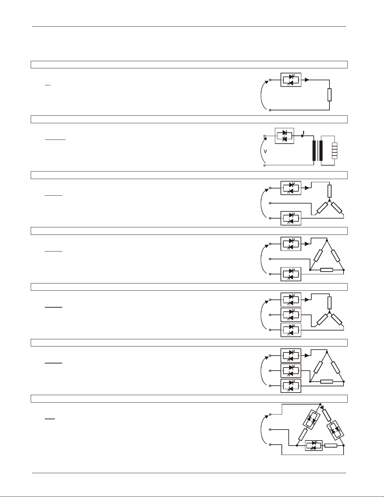
7 Basic Connections and sizing
Single phase wiring with resistive load (with REVO M-1PH)
P
I =
V = Nominal voltage of the load
I = Nominal current of the load
P = Nominal power of the load
Single phase wiring with inductive load (with REVO M-1PH)
P
I =
V = Nominal voltage phase to phase
I = Nominal current to the load
P = Nominal power to the load
Star wiring with resistive load (control on two phases with REVO M-2PH)
I
=
V = Nominal voltage of the load
I = Nominal current of the load
P = Nominal power of the load
Delta wiring with resistive load (control on two phases with REVO M-2PH)
I
=
V = Nominal voltage of the load
I = Nominal current of the load
P = Nominal power of the load
Star wiring with resistive load (control on three phases with REVO M-3PH)
I
=
V = Nominal voltage of the load
I = Nominal current of the load
P = Nominal power of the load
Delta wiring with resistive load (control on three phases with REVO M-3PH)
I
=
V = Nominal voltage of the load
I = Nominal current of the load
P = Nominal power of the load
Open Delta wiring with resistive load (with 3 X REVO M-1PH)
P
I3=
V = Nominal voltage of the load
I = Nominal current of the load
P = Nominal power of the load
φ
cosV
P
V
731,
P
V
731,
P
V
731,
P
V
731,
V
V
V
V
V
I
V
REVO_M08
10
Page 11
CD Automation srl REVO M User’s Manual
8 Identification and Order Code
8.1 Identification of the unit
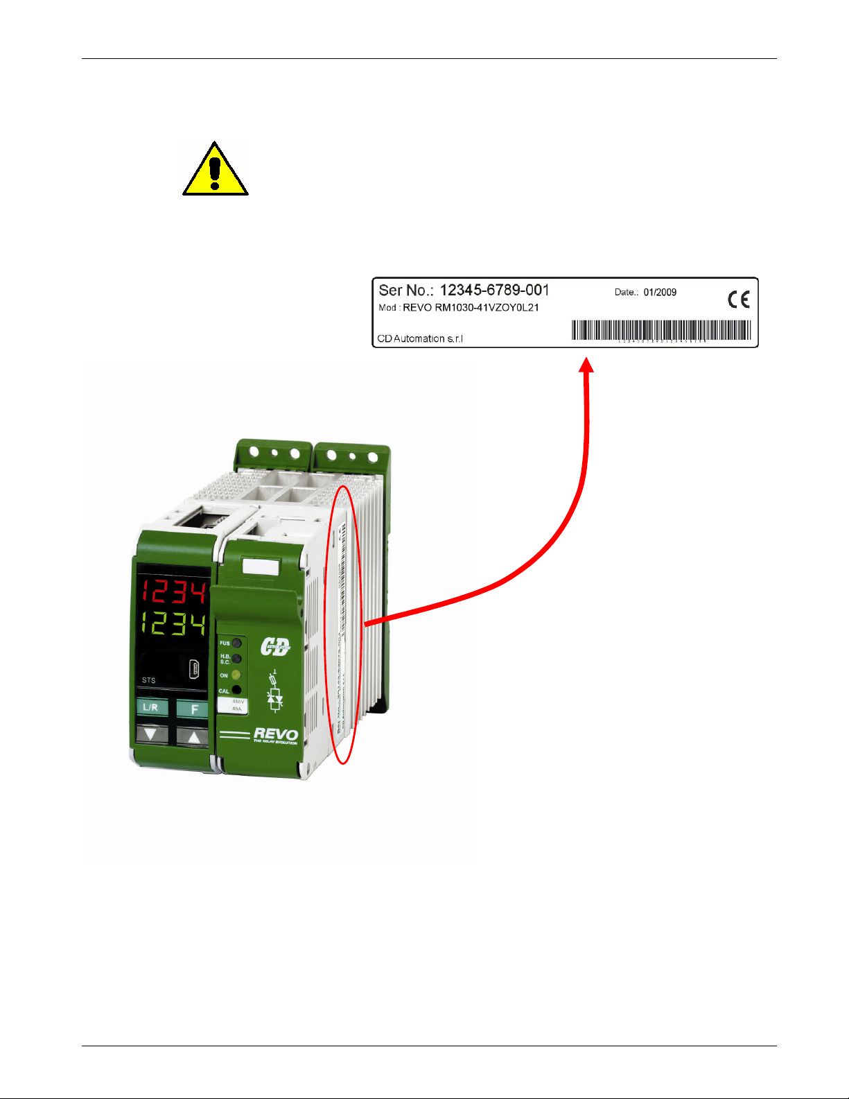
Caution: Before to install, make sure that the Thyristor unit
have not damages. If the product has a fault, please contact
The identification's label give all the information regarding the factory settings of the Thyristor unit, this
label is on the unit, like represented in figure.
Verify that the product is the same thing as ordered.
the dealer from which you purchased the product.
REVO_M08
11
Page 12
CD Automation srl REVO M User’s Manual
1PH 1
2PH 2
3PH 3
30A With Heat
-
sink (this size is not available on 1PH)
0 3 0
35A With Heat
-
sink 0 3 5
40A
With Heat
-
sink 0 4 0
45A With Heat
-
sink (this size is available on 1PH only)
0 4 5
480V
4
600V
6
90:130V
1
170:265V
2
230:345V
3
300:530V
5
510:690V
6
0-10V dc
V
4-20 mA
A
10k Pot
K
SSR S
ZC Zero Crossing
Z
BF Burst Firing
B
SC Single Cycle (only 1PH unit)
C
S+BF Soft Start + Burst Firing1 (only 1PH unit)
J
PA Phase Angle (only 1PH unit)
P
PA+S Phase Angle + Soft Start (only 1PH unit)
E
DT Delayed Triggering1
(only 1PH unit)
D
None
0
V Voltage (available with BF,SC,S+BF and DT)
U
VxI Power (available with BF,SC,S+BF and DT)
W
IFH (
≤45A) or IF(>45A) + CT
Y
IFH (
≤45A) or IF(>45A) + CT + HB
H
None
0
110V fan option available
≥ 120A
1
None
0
cUL us (soon available)
L
None
0
Italian
1
English
2
German
3
French
(soon availabl
e) 4
Version 1
1
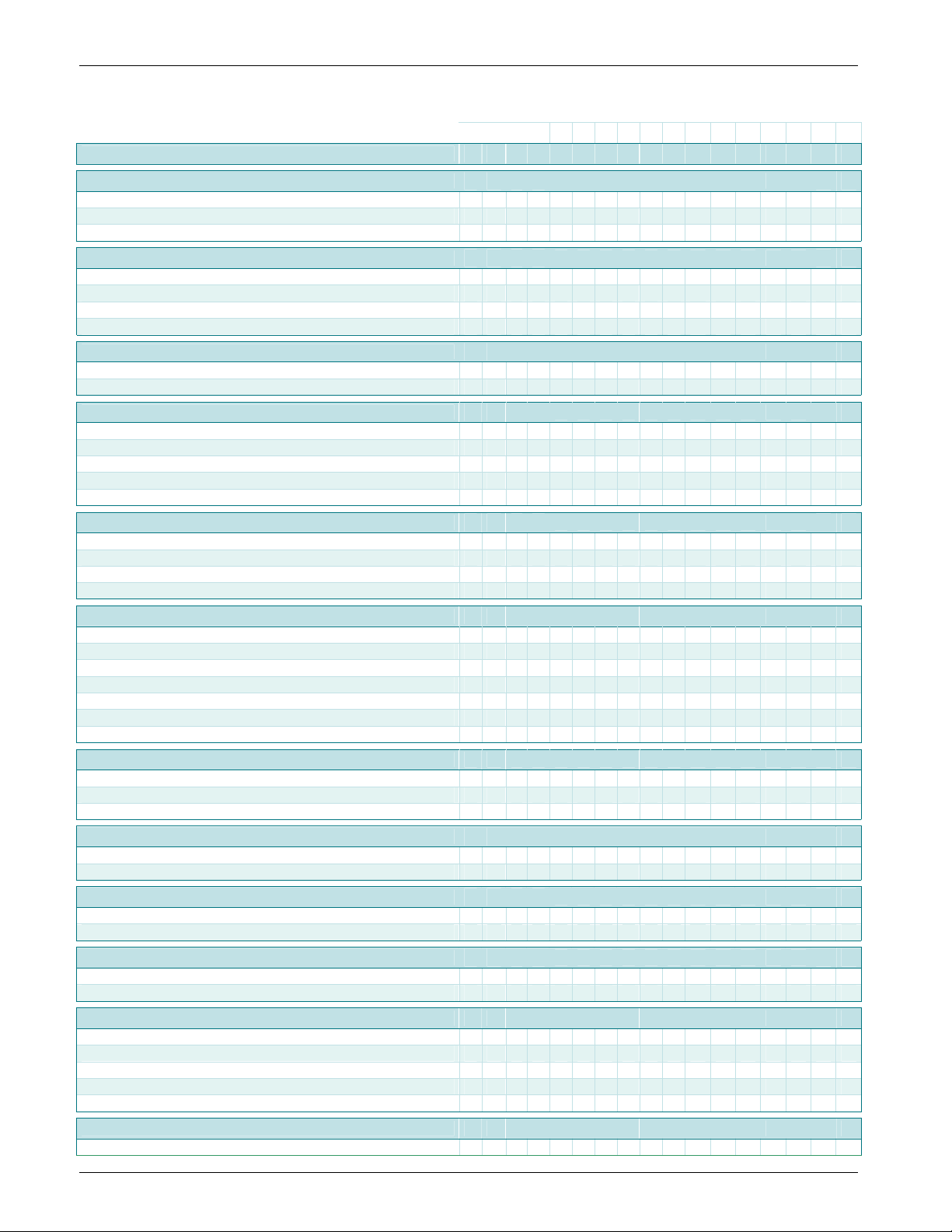
8.2 Order Code
1 2 3 4 5 6 - 7 8 9 10 11 12 13 14 15 16
CODE
PHASES CONTROLLED
R M _ _ _ _ - _ _ _ _ _ _ _ _ _ _
Current Rathing
MAX VOLTAGE
Load Voltage and Aux.Voltage Supply Range
INPUT
Firing
Control Mode
Options
110V fan option
Approval
Manual
Version
REVO_M08
12
Page 13
CD Automation srl REVO M User’s Manual
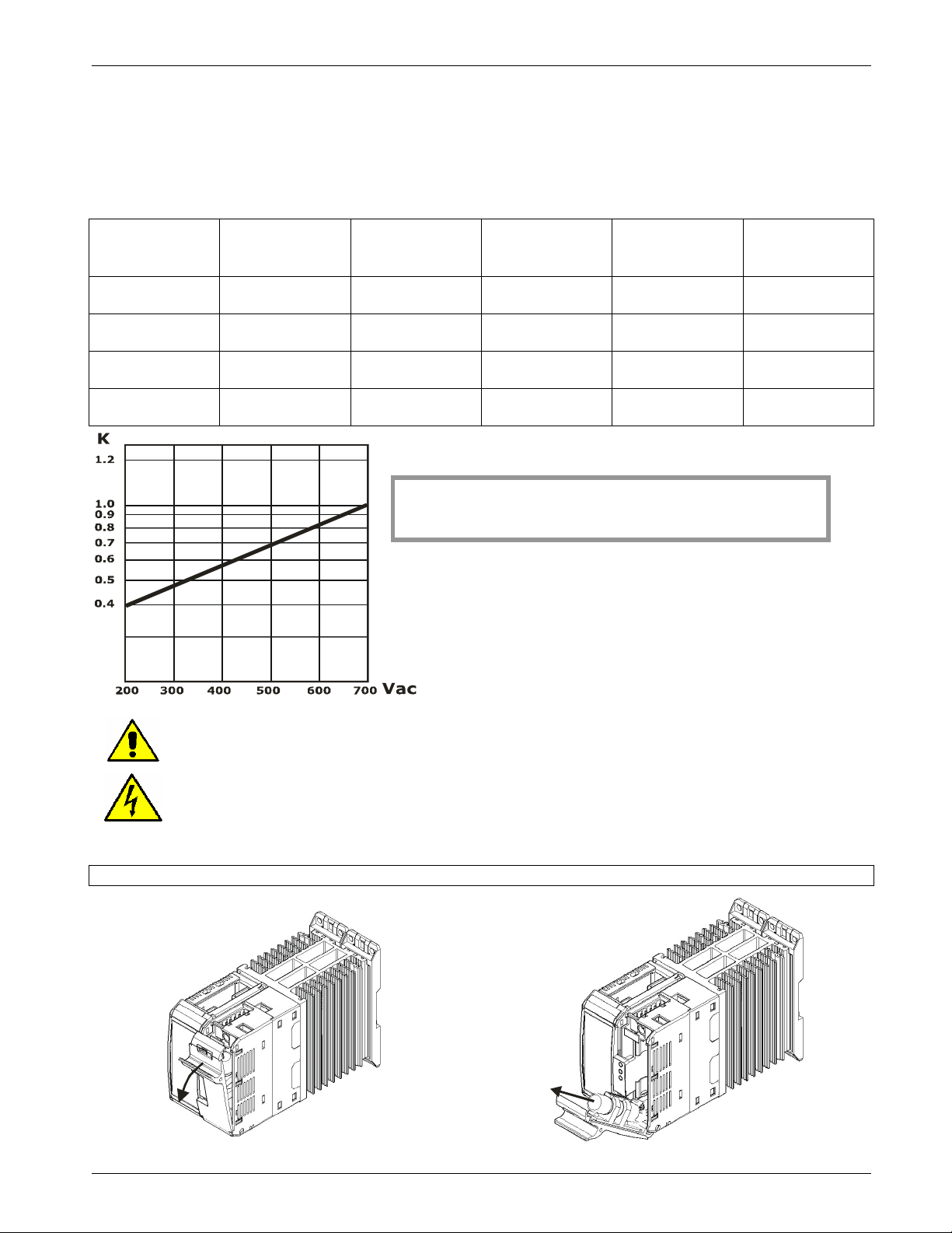
9 Internal Fuse
The thyristor unit have internal fuse extrarapid at low I²t for the thyristor protection of
against the short-circuits.
The Fuses must have I²t 20% less than thyristor's I²t. The warranty of thyristor is null
if no proper fuses are used.
Type
030 FU1451/40A 40 980 660 9
035 FU1451/50A 50 1800 660 9
040 FU1451/50A 50 1800 660 9
045 FU1451/50A 50 1800 660 9
Caution: High speed fuses are used only for the thyristor protection and can not be used to
protect the installation.
Caution: The warranty of thyristor is null if no proper fuses are used. See tab.
Fuse Code
Spare Part
Vac
The I²t on the table is related to 660 Vac, for real
value see this correction factor graphic.
Current
(ARMS)
I²T
(A² sec.)
Max Power
Lost (W)
Warning: When it is supply, the Thyristor unit is subject to dangerous voltage, don't open
the Fuse-holder module and don’t touch the electric equipments.
9.1 Fuses Replacement
Open the Fuse-Holder Pull out the fuse
REVO_M08
13
Page 14
CD Automation srl REVO M User’s Manual
10 Installation
Before to install, make sure that the Thyristor unit
have not damages.
If the product has a fault, please contact the
dealer from which you purchased the product.
Verify that the product is the same thing as
ordered.
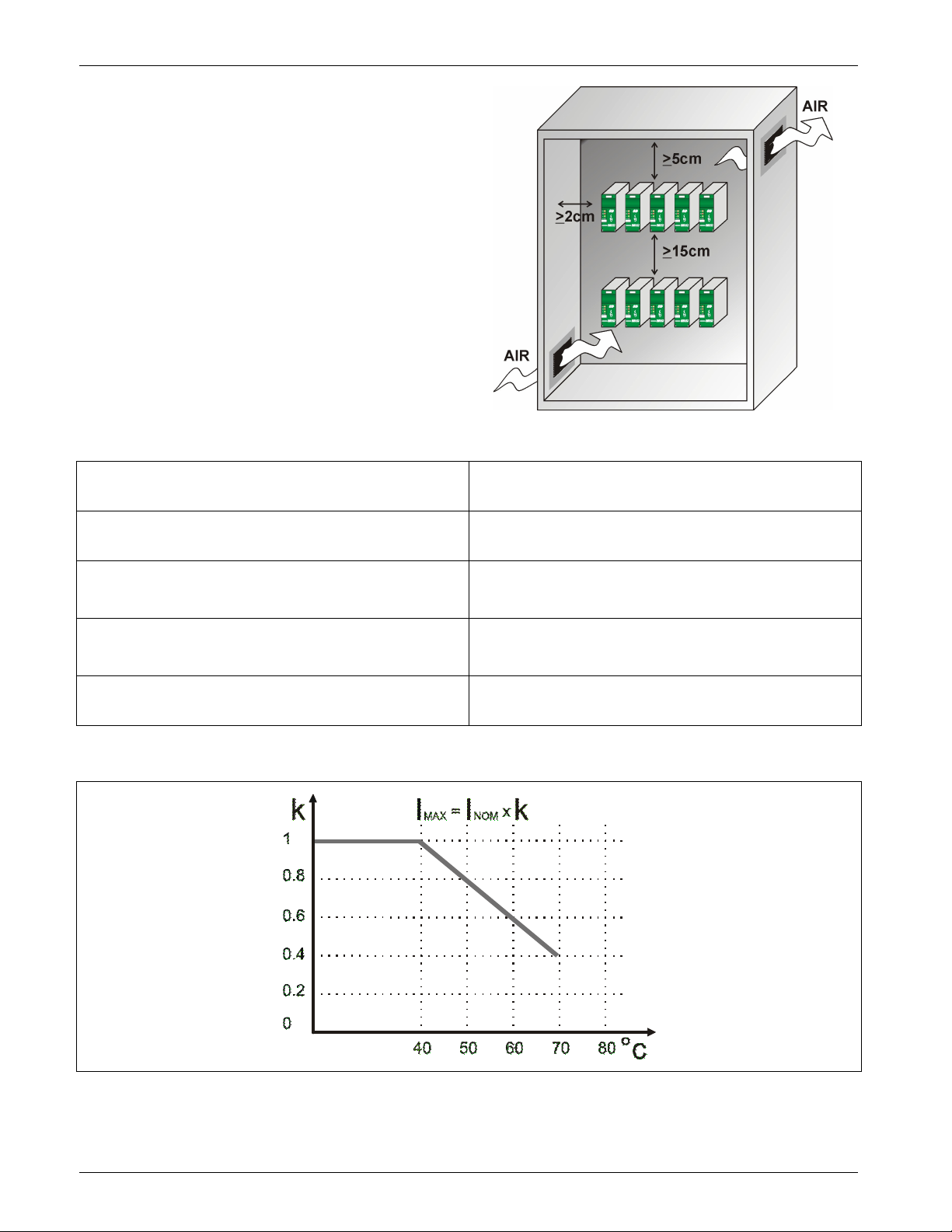
The Thyristor unit must be always mounted in
vertical position to improve air cooling on heatsink.
Maintain the minimum distances in vertical and in
horizontal as represented.
When more unit has mounted inside the cabinet
maintain the air circulation like represented in
figure.
Sometimes is necessary installing a fan to have
better air circulation.
10.1 Environmental installation conditions
Ambient temperature
Storage temperature -25°C a 70°C
Installation place
Altitude
Humidity From 5 to 95% without condense and ice
0-40°C at nominal current. Over 40°C use the
derating curve.
Don’t install at direct sun light, where there are
conductive dust, corrosive gas, vibration or water
and also in salty environmental.
Up to 1000 meter over sea level. For higher
altitude reduce the nominal current of 2% for each
100m over 1000m
10.2 Derating Curve
REVO_M08
14
Page 15
CD Automation srl REVO M User’s Manual
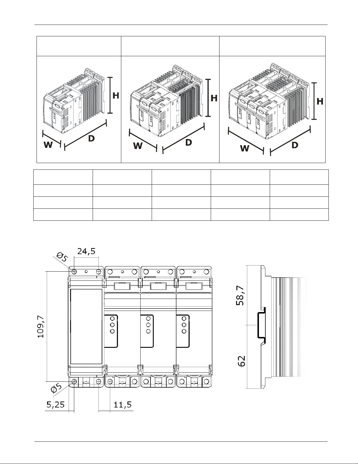
10.3 Dimensions and Weight
REVO M 1PH REVO M 2PH REVO M 3PH
Size W(mm) H(mm) D(mm) Weight (kg)
1PH 72 120,7 184 1,148
2PH 108 120,7 184 1,756
3PH 144 120,7 184 2,354
10.4 Fixing holes
REVO_M08
15
Page 16
CD Automation srl REVO M User’s Manual
57W for unit type 045
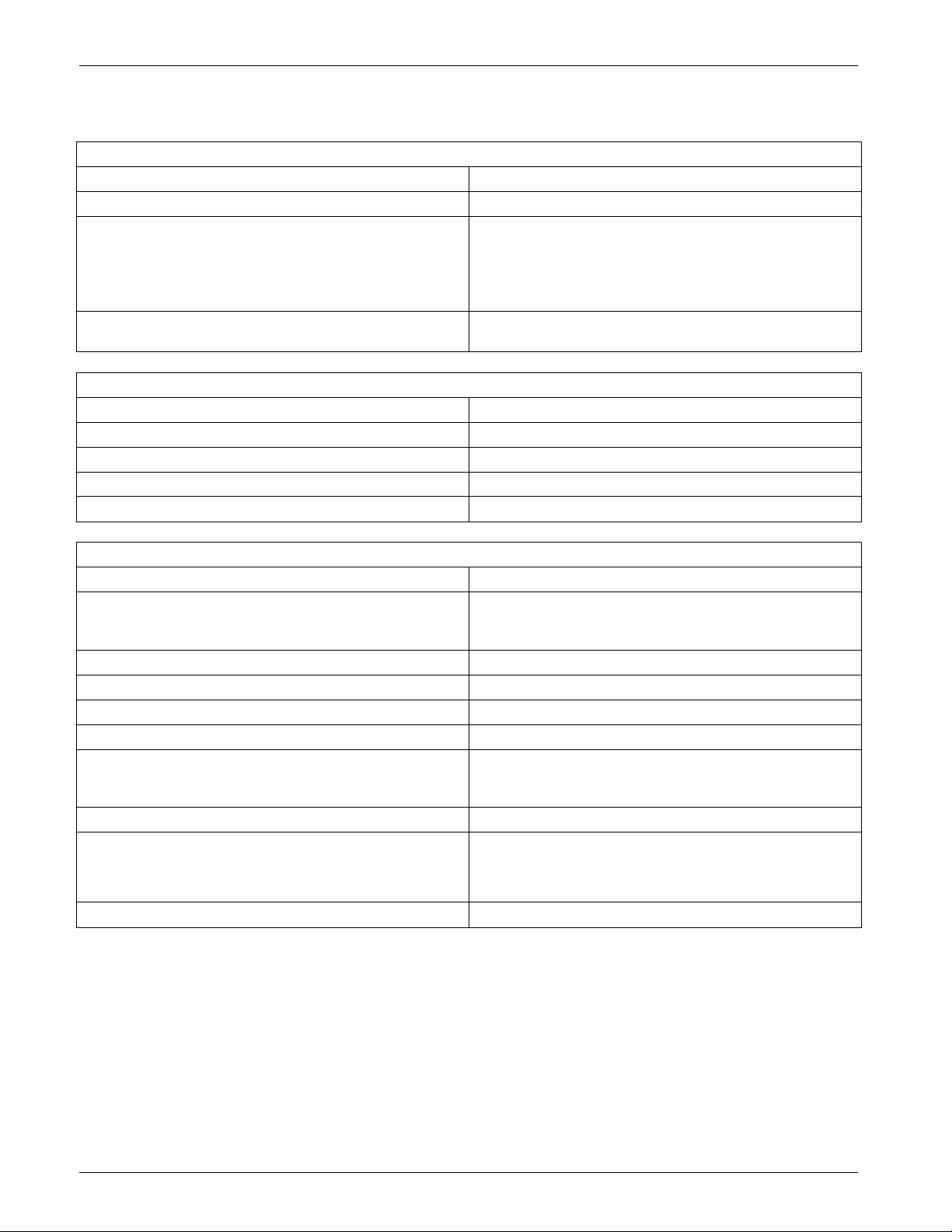
10.5 Technical Specifications
General features:
Cover and Socket material: PolymericV2
Mounting: DIN bar
90:130V
170:265V
Auxiliary voltage:
230:345V
300:530V
510:690V
Relay output for Heater Break Alarm
(only with HB option):
0.5A a 125VAC
Input features:
Logic input SSR: 4 ÷ 30Vdc 5mA Max (ON ≥ 4Vdc OFF < 1Vdc)
Analogic input
Analogic input
0 ÷ 10Vdc impedance 15 K ohm
4 ÷ 20mA impedance 100 ohm
POT 15 K ohm min.
Digital Input 4 ÷ 30Vdc 5mA Max (ON ≥ 4Vdc OFF < 1Vdc)
Output features(power device):
Nominal current in continuous service: See order code
400A for unit type 030
Max peak current (10ms)
600A for unit type 035
800A for unit type 040-45
Voltage range: 24÷600V
Repetitive peak reverse voltage: 1200V
Latching current: 250mA
Leakage current: 15mA eff
830 A/s for unit type 030
I²T value tp=10msec:
1750 A/s for unit type 035
3110 A/s for unit type 040-45
Frequency range: 47÷70Hz
38W for unit type 030
Power loss (I=Inom):
44W for unit type 035
50W for unit type 040
Isolation Voltage: 2500Vac
REVO_M08
16
Page 17
CD Automation srl REVO M User’s Manual
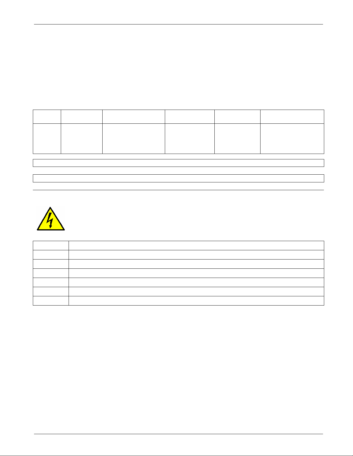
Use copper cables and wires rated for use at 75°C only
.
11 Wiring instructions
The Thyristor unit could be susceptible to interferences lost by near equipments or by the power supply,
for this reason in accord to the fundamental practices rules is opportune take some precautions:
• The coil contactor, the relays and other inductive loads must be equipped with opportune RC filter.
• Use shielded bipolar cables for all the input and output signals.
• The signal cables must not be near and parallel to the power cables.
• Local regulations regarding electrical installation should be rigidly observed.
Power cable torque (suggested)
Type
030
035
040
045
Connector
Type
Screw M5 26.6 (3.0) 1.5-10 (16-8)
Cable dimensions of the Command Terminals
0.5mm² (AWG 18)
Cable dimensions of the Earth (suggested)
6 mm² (AWG 10)
Torque
Lb-in (N-m)
Wire Range
mm²(AWG )
MAX Current
Terminals
45A
Wire Terminals
UL Listed (ZMVV)
Rigid / Flexible
Spade Terminal
Warning: Before connecting or disconnecting the unit check that power and control cables
are isolated from voltage sources.
Terminal Description
L1 Line Input Phase 1
T1 Load Output Phase 1
L2 Line Input Phase 2 (only for 3pH)
T2 Load Output Phase 2 (only for 3pH)
L3 Line Input Phase 3 (only for 2Ph and 3Ph)
T3 Load Output Phase 3 (only for 2Ph and 3Ph)
REVO_M08
17
Page 18
CD Automation srl REVO M User’s Manual
11.1 Command Terminals
Warning: Before connecting or disconnecting the unit check that power and control cables
are isolated from voltage sources.
11.1.1 Terminal block M2 Drive M
Terminal Description
1 GND
2 COM digital Input
3 Configurable Enable
4 Configurable Input1
5 Control Input +
6 Control Input -
7 +10V Output
8 Slave Output - (factory connection)
9 Slave Output + (factory connection)
11.1.2 Terminal block M1 Drive M
Terminal Description
10 GND
11 TA1 Input (factory connection)
12 TA1 or TA2 input (factory connection)
13 TA3 input (factory connection)
14 Common alarm relay output
15 Normally open alarm relay output
16 Normally close alarm relay output
11.1.3 Terminal block M3 Drive M
Terminal Description
A+ RS485
B- RS485
11.1.4 Terminal block M4 Drive M
Terminal Description
L1 Aux L1
- Not Connected
L2/N Aux L2/N
REVO_M08
18
Page 19
CD Automation srl REVO M User’s Manual
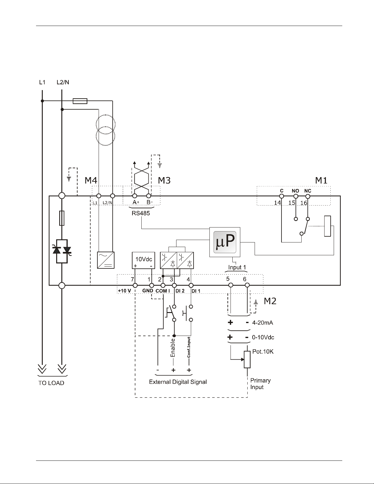
11.2 Schematic
REVO_M08
19
Page 20
CD Automation srl REVO M User’s Manual
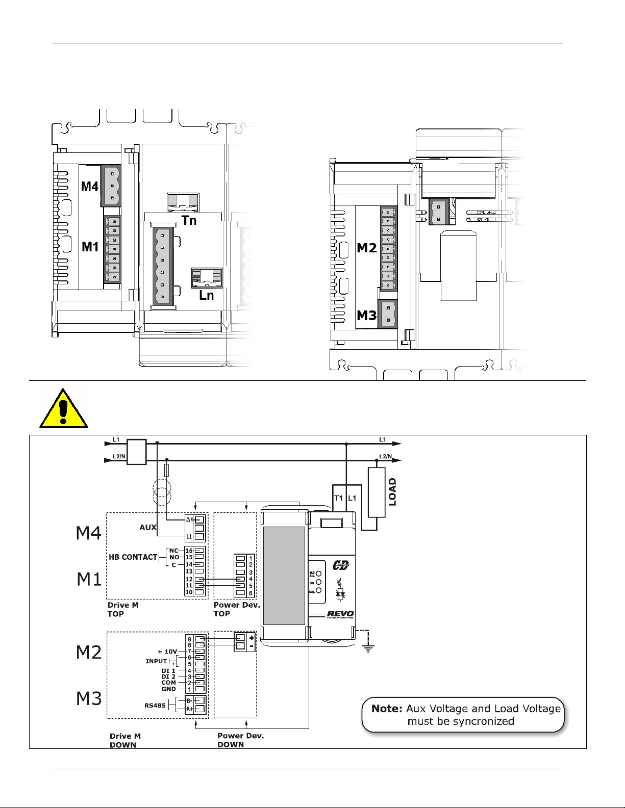
11.3 Connection Diagram for Single-phase
TOP VIEW DOWN VIEW
Caution: this procedure must be performed only by qualified persons.
REVO_M08
20
Page 21
CD Automation srl REVO M User’s Manual
T1T2T3
T1T2T3
11.4 Connection Diagram for 3 phases (control on 2 phases)
Caution: this procedure must be performed only by qualified persons.
REVO_M08
Load Type
Delta Star
21
Page 22
CD Automation srl REVO M User’s Manual
T1T2T3
T1T2T3L1L3
L2
T1T2T3
T1T2T3
N
11.5 Connection Diagram for 3 phases (control on 3 phases)
Caution: this procedure must be performed only by qualified persons.
Load Type
Delta Open Delta Star Star + Neutral
REVO_M08
22
Page 23
CD Automation srl REVO M User’s Manual
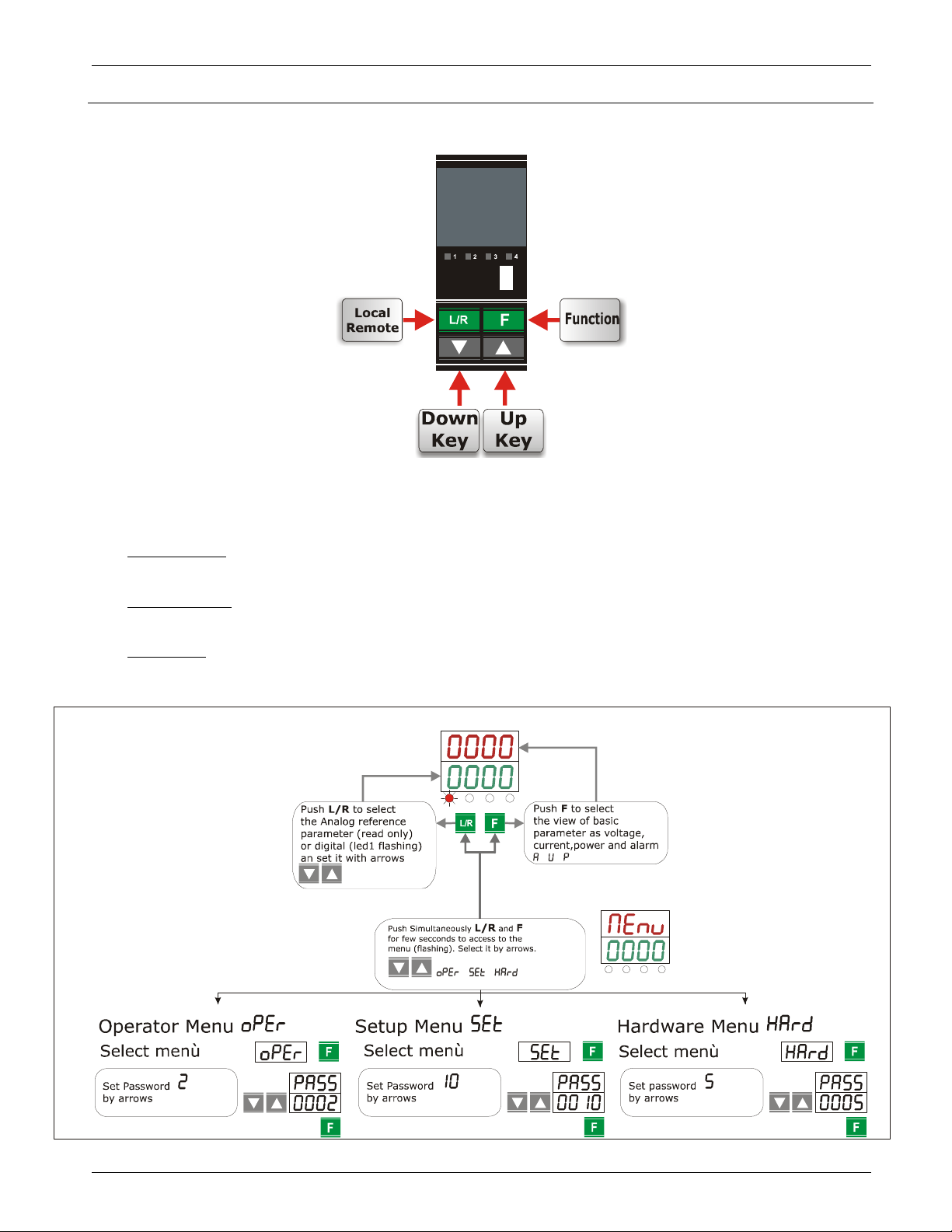
12 Control Panel
The Control Panel is placed on the front of the thyristor unit, on his display you can visualize the alarms, the input
and output signals and all the configuration parameters.
The function keys is the following:
• The Function key is used for enter and exit from the menu.
• The UP key and DOWN key is used to scroll the parameters in the menu and to change data.
• The ENTER key is used to edit the parameters and to save the modified values.
The Control Panel have three menu, and to enter in one of them you must set correctly the parameter :
• Operator Menu ( = 2)
This menù contains a reading parameters that give information on the state of the unit, it include also the base
parameters for quick start, like the value of current and voltage load and the Set-point data.
• Hardware Menu ( = 5)
This menu contains all the configuration parameters for analogic and digital I/O, and the parameters to set the
serial port like the address and the baudrate.
• Setup Menu ( = 10)
This menù contains all the setting parameters to configure the thyristor unit, like the firing type, the current
limit, [ecc].
REVO_M08
23
Page 24
CD Automation srl REVO M User’s Manual
12.1 Scroll the parameters
REVO_M08
24
Page 25

CD Automation srl REVO M User’s Manual
Phase Angle PA (available only on 1PH).
13 Input output signal
13.1 Digital Input
The REVO M thyristor unit has 2 digital inputs opto-isolated to 24Vdc 5 mA.
You can activate the inputs with the internal supply or with an external source for example the PLC.
13.1.1 Start/Stop (Terminal 3 of M2)
This is the start command (Enable) of the REVO M.
If you Remove the Start command the REVO M thyristor unit will be stopped and the output will return
at zero.
13.1.2 Configurable Input (Terminal 4 of M2)
This digital input is configured by the parameter and could perform different functions:
• Enable:
This function forces the output at zero.
• Feed-Back Selection:
With this function, when you active the input, the feed-back setted in the parameter change in
Voltage Feed-Back (V).
• Analog/Digital Setpoint(Local/Remote:
With this function, when you active the input, the setpoint reference change from Analog input to
Digital value, setted in the parameter .
• Change Firing type:
With this function, when you active the input, the Firing type setted in the parameter change in
13.2 Digital Output terminal (terminal 14-15-16 of M1)
The REVO M thyristor unit has 1 relay output on terminal 14-15-16 of terminal block M1
(Max 500mA, 125Vac). The functionality of this output cane be setted with the parameter
This digital output can be configured in order to activate itself after that one of these alarms occours:
• HB and SC alarm are active.
• Only HB alarm is active.
• Only SC alarm is active.
13.3 Analog Input
Primary Input (Terminals 5 and 6 of M2)
The REVO M thyristor unit has 1 analog inputs (0÷10V, 0÷20mA, 4÷20mA ecc):
The primary input for the analog setpoint.
The primary input is already configured in line with customer requirements that are defined in the Order
Code. The Order Code is written on the identification label.
However, if you wish to change the primary input (ex. from 0÷10V to 0÷20mA, 4÷20mA).
REVO_M08
25
Page 26

CD Automation srl REVO M User’s Manual
14 Heater Break alarm and SCR short circuit (HB Option)
Caution: to work properly the load must be powered at least about 160msec.
The Heater Break circuit read the load resistance with an Internal voltage transducer and Internal
current transformer (C.T.), to calcolate the resistance (V/I).
Minimum current is 10% of the current transformer size.
If load current is below this value the Heater Break Alarm doesn’t work properly.
14.1 Heater break Calibration procedure
An automatic function sets the Heater Break Alarm.
Write in the parameter
If load current decreases for partial or total load failure (sensitivity 20%) HB alarm become ON and
alarm relay change status.
If the unit is still in conduction with no input signal (LED green OFF) it means that there is a short circuit
on thyristors and (SC) become ON.
You can Adjust the sensibility of HB alarm by using the parameter
between 1 and 255% of the nominal resistance.
This parameter is the maximum reduction of the resistance Load to establish the HB Alarm.
There is also
parameter to set a delay to have HB alarm active.
and
This parameter is setted
14.2 HB alarm contact (digital output)
The Revo unit with HB option, is supplied with Heater Break alarm contact normally opened (NO):
• In normal conditions (without alarm) and with auxiliary power supply, the contact to the terminals
has opened (relay coil energized).
• In alarm condition or without auxiliary power supply the contact to the terminals is closed (relay coil
not energized).
This alarm can be configured in order to activate itself after that one of these alarms occours:
• HB and SC alarm are active.
• Only HB alarm is active.
• Only SC alarm is active.
• Disable the relay output.
REVO_M08
26
Page 27
CD Automation srl REVO M User’s Manual
VOLTAGE SUPPLY (V)
15 Firing type
Choose an correct firing type allows to optimize the thyristor unit for the installed load.
The firing type has already configured in line with customer requirements that are defined in the Order
Code. The Order Code is written on the identification label.
However, if you wish to change the firing type you can use the software configurator or the Control
Panel.
Caution: this procedure must be performed only by qualified persons.
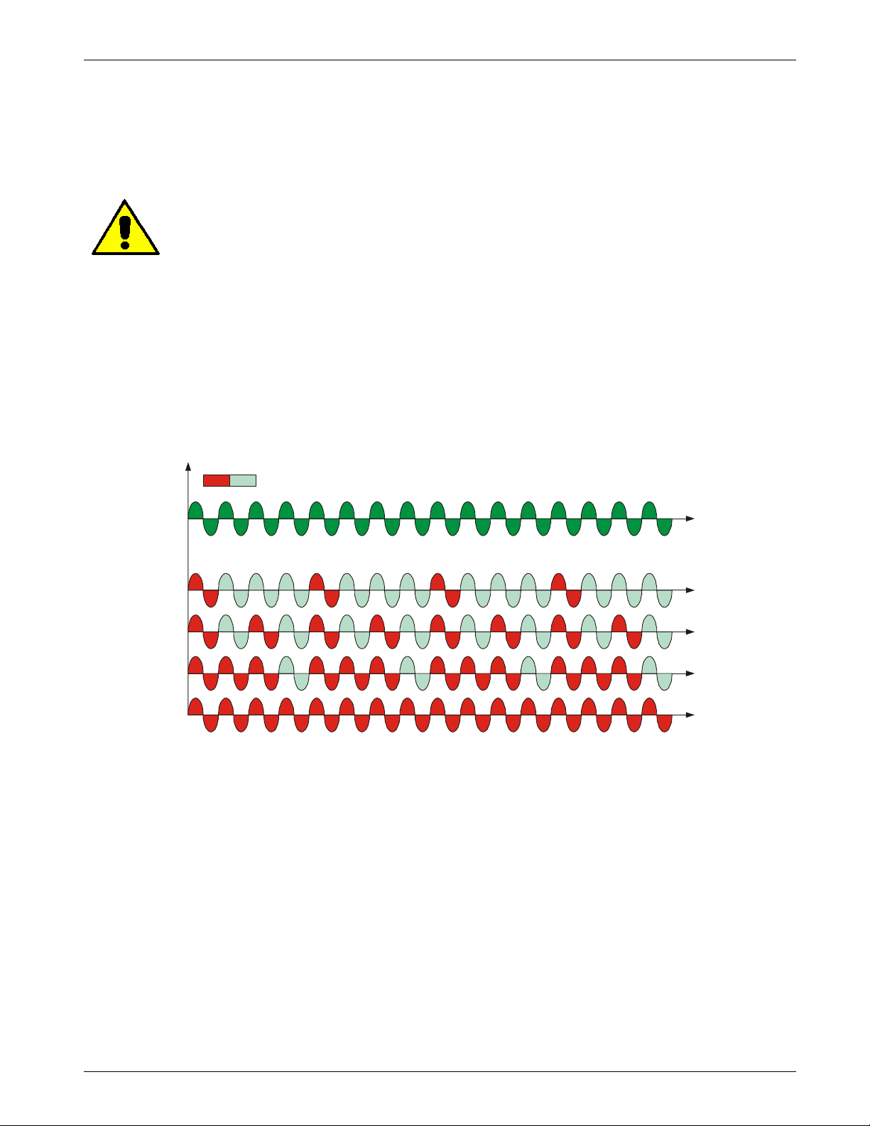
15.1 Single Cycle SC (1Ph Only)
Single Cycle it's the faster zero crossing switching method in relationship of the power demand from a
temperature regulator or from an external signal.
With input signal at 25% the output is one cycle ON and three cycles OFF
With input signal at 50% the output is one cycle ON and one cycle OFF
With input signal at 75% the output is three cycles ON and one cycle OFF
With input signal at 76% the output is the same of 75% but for each ON cycle the microprocessor
divides 76/75, and when the sum of rests is one, the unit does one more cycle ON. For this firing is
necessary to have analog input.
The Single Cycle is used to control the loads with low inertia or for infrared lamps to short wave.
ON OFF
LOAD VOLTAGE (V)
25%
50%
75%
100%
REVO_M08
27
Page 28
CD Automation srl REVO M User’s Manual
VOLTAGE SUPPLY (V)
VOLTAGE SUPPLY (V)
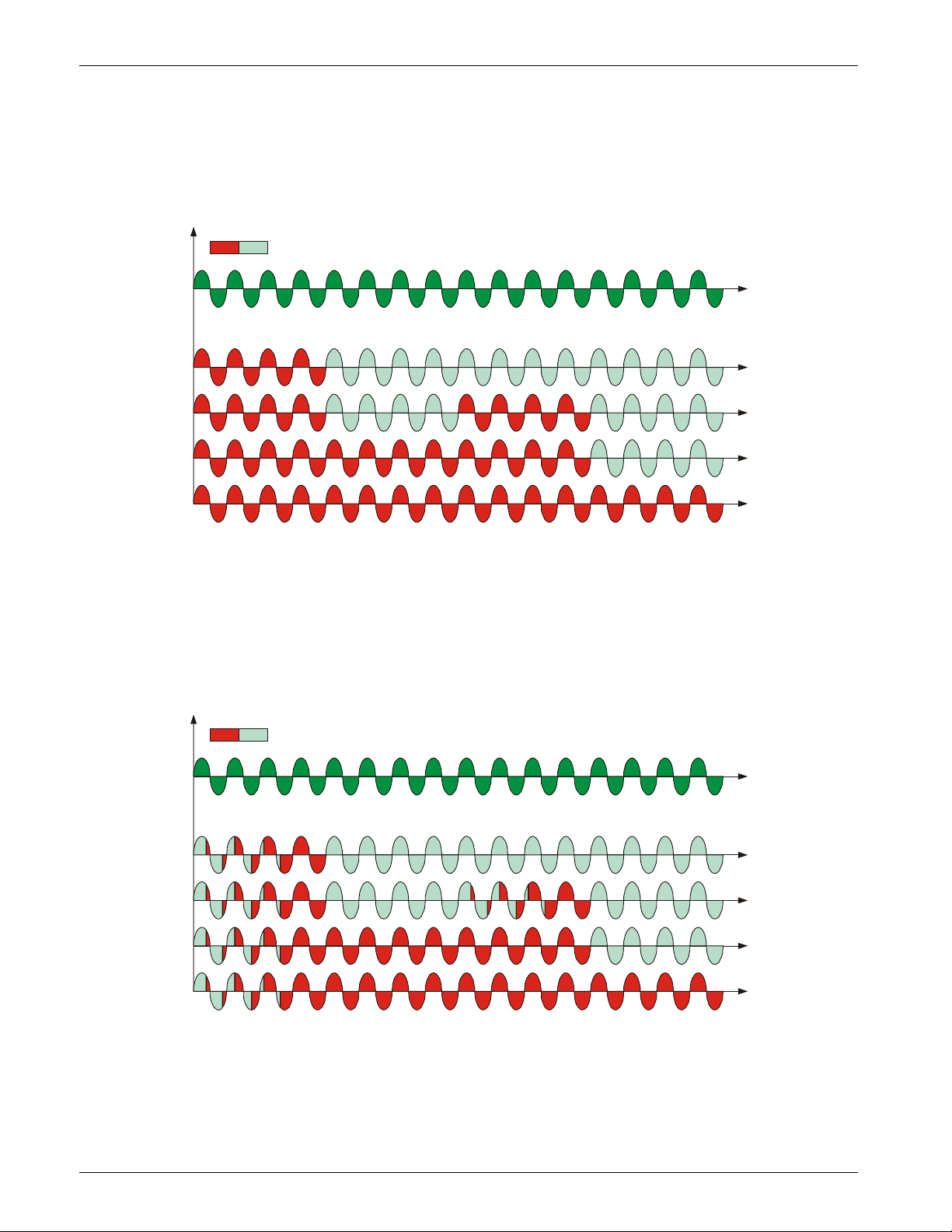
15.2 Burst Firing (BF)
The Burst Firing is similar to the Single Cycle, but consecutive cycles ON are selectable between 2 and
255, with input signal equal at 50%.
Burst Firing is a method zero crossing that it reduces the electromagnetic interferences because the
thyristor switches at zero voltage crossing.
The example show the Burst Firing with Burst cycles: =4
ON OFF
LOAD VOLTAGE (V)
25%
50%
75%
100%
15.3 Soft Start with Burst Firing S+BF (1Ph Only)
This is an additional function to the Burst Firing. The unit start in phase angle mode with a ramp starting
from zero up to the full tension in the cycles number set in the parameter .
When the ramp is over, the thyristor unit will stay in conduction at full voltage up to the end of cycles of
burst. The S+BF firing is used to control small inductive loads to avoid inrush surge current and to
reduce the electromagnetic interferences.
The example show the firing with Burst cycles: =4 and ramp cycles: =3
ON OFF
LOAD VOLTAGE (V)
25%
50%
75%
REVO_M08
100%
28
Page 29
CD Automation srl REVO M User’s Manual
VOLTAGE SUPPLY (V)
VOLTAGE SUPPLY (V)
Setpoint Value (%)
Ramp Down
Load voltage RMS (V)
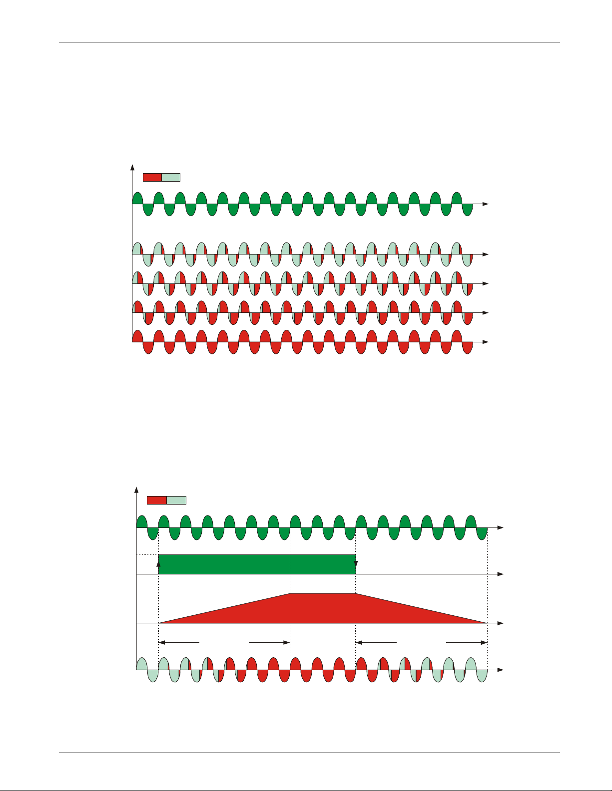
15.4 Phase Angle PA (1Ph Only)
The Phase Angle firing allow the control of the power on the load, for this firing the thyristor can be in
conduction only for a part of the voltage cycle.
This part of the voltage cycle is adjustable in function of the input signal from 0 at 100%.
The PA firing is normally used for control the inductive loads, and is also possible control a primary of
transformer coupled with the cold resistances like: Superkanthal, Molybdenum, Platinum, Tungsten or
Quartz Lamp. The only disadvantage with phase angle is the possible generation of interferences that
however can be reduced with opportune filters.
ON OFF
LOAD VOLTAGE (V)
25%
50%
75%
100%
15.5 Soft Start with Phase Angle (S+PA)
This is an additional function to the Phase Angle. The firing angle of the thyristor increase or decrease
up to the final setpoint value.
The Soft start ramp is an important feature to reduce the inrush current with transformers during the
during the cycle of magnetization or with cold resistance that are near to the short circuit when they are
supplied.
Setpoint Ramp Up :
Setpoint Ramp Down:
ON OFF
100%
0%
REVO_M08
Ramp Up
OUTPUT VOLTAGE (V)
29
Page 30
CD Automation srl REVO M User’s Manual
over-current
y
V
1
I
1
3
V
x
i
2
i
1
V
1
I
1
3
x
i
2
Delay Angle
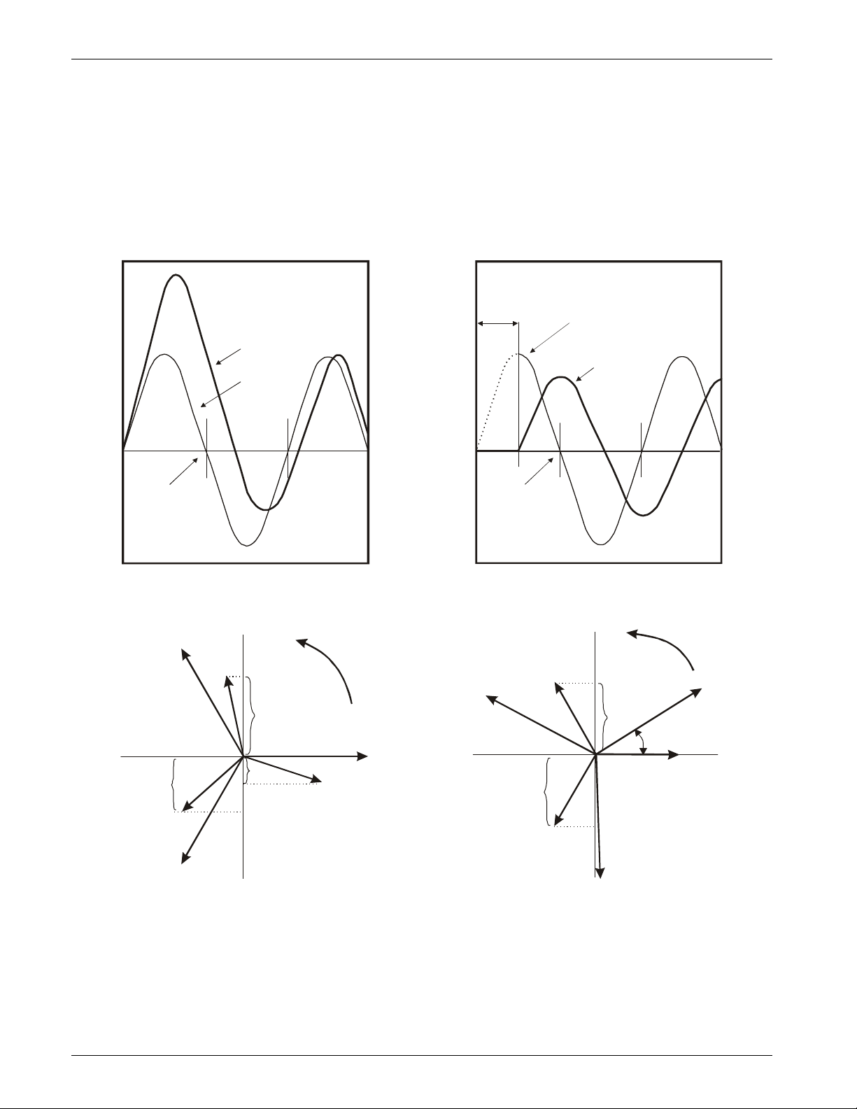
15.6 Delay Triggering DT (1Ph Only)
The Delay Triggering firing is used the control a primary of transformer coupled with the normal
resistances on the secondary (N.B. don't connect cold resistances on the secondary like: Superkanthal,
Molybdenum, Platinum, Tungsten, Quartz Lamp).
For an inductive load (ex transformer), switching the thyristors at zero crossing can generates transient
over currents that can blow the fuses, to avoid this problem you must use the Delay Triggering. This
firing delay the first half cycle of Burst for an angle from 0 to 100° relative to the zero, besides all the
first burst start with soft start ramp to reduce the inrush current during the cycle of magnetization.
Without Delay Triggering With Delay Triggering
Transient
Delay angle
(0° to 100°)
Voltage
Current
Voltage
0
Zero
Crossing
Voltage
For understand the Delay Triggering firing, we have represented the waves generate by vectors that
rotates in counterclockwise:
Without Delay Triggering With Delay Triggering
2
I
2
0
Zero
Crossing
Voltage
V
2
I
2
Current
y
α
i
3
I
3
V
Without delay at zero crossing when V1 is to zero (projected on the X axis) the unit switch On.
In this case the instantaneous value of the currents are i1, i2 and i3 and this condition, for the curve of
magnetization, could generate transient over currents that can blow the fuses.
With Delay Triggering the firing of the thyristor are triggered with a delay until the instantaneous value
of the curret i1=0, i2 positive and i3 negative like represented.
In this case the risk of transient over currents is reduced and the fuses don't blow.
The angle alpha is the delay to have i1=0 and this angle depends on the power factor.
The delay angle suggest for most applications is 80°
REVO_M08
30
i
3
I
3
V
Page 31

CD Automation srl REVO M User’s Manual
16 Feed-back type
The Feed-back type has already configured in line with customer requirements that are defined in the
Order Code. The Order Code is written on the identification label.
However, if you wish to change the Feed-back type you can use the software configurator or the Control
Panel.
Caution: this procedure must be performed only by qualified persons.
The Feed-back type is defined by the parameter .
If the configurable digital input has set like Feed-Back Selection ,it's possible to change the select FeedBack with the Voltage Feed-Back (V) simply activating the input.
The feed-back defines the Control Mode. It’s possible to have:
• V=Voltage feed-back.
The input signal is proportional to the output voltage. This means that input signal becomes a
voltage demand. This control mode compensates the voltage fluctuation of the incoming line supply.
• I=Current feed-back.
The input signal is proportional to the current output. This means that input signal becomes a
current demand. This control mode maintain the current also if the load impedance changes.
• W=Power feed-back.
The input signal is proportional to the power output. This means that input signal becomes a power
demand. The power remains constant also if voltage and load impedance change. This control mode
is used with silicon carbide elements that change its resistive value with temperature and with age.
In addition it compensates the voltage fluctuation of the incoming line supply.
• V2=Square Voltage feed-back.
The input signal is proportional to the output square voltage. This means that input signal becomes
a power demand. The power remains constant if the load impedance doesn't change.
• NO=No Feedback Open Loop. The input is proportional to the firing angle ( α ).
REVO_M08
31
Page 32
CD Automation srl REVO M User’s Manual
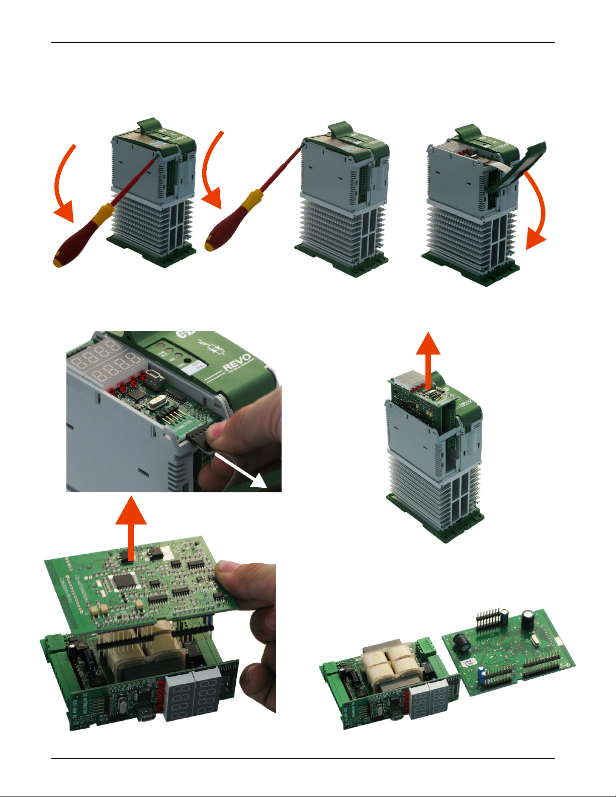
17 Electronic boards
17.1 How to access
REVO_M08
32
Page 33
CD Automation srl REVO M User’s Manual
defined in the Order Code. The Order Code is written on the identification label.
M4
17.2 Supply the Electronic Board
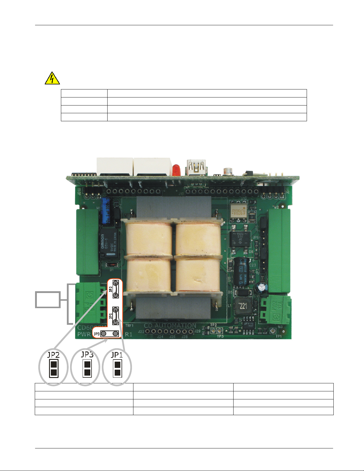
The REVO M thyristor unit, to work, requires a voltage supply for the electronic boards. The Max
consumption is 10VA.
The voltage supply for the electronic boards is configured in line with customer requirements that are
Warning: Before connecting or disconnecting the unit check that power and control cables
are isolated from voltage sources.
Terminal M4
1 Voltage Supply for Electronic Boards (Auxiliary Voltage)
2 Not Used
3 Voltage Supply for Electronic Boards (Auxiliary Voltage)
To change auxiliary supply voltage sold the correct link-jumper on CD6000M board
The type of mounted transformer depends of the chosen Voltage in the order code.
Description
Transformer Type Link-Jumper JP1+JP2 Link-Jumper JP3
TR-605 120V 90:130V TR-605 230V 170:265V 300:530V
TR-605 300V 230:345V 510:690V
If the Auxiliary Voltage (written on the identification label) is different from Supply Voltage (to the load),
use an external transformer with primary equal to load voltage and secondary equal to the Auxiliary
Voltage
REVO_M08
33
Page 34
CD Automation srl REVO M User’s Manual
17.3 Analog Inputs
The REVO M thyristor unit has 2 configurable analog inputs (0÷10V, 4÷20mA, ecc):
The primary input for the analog setpoint, the secondary input for the Current Profiler or Ext. Feed-Back.
17.3.1 Primary Input (Terminals 5 and 6 of M2)
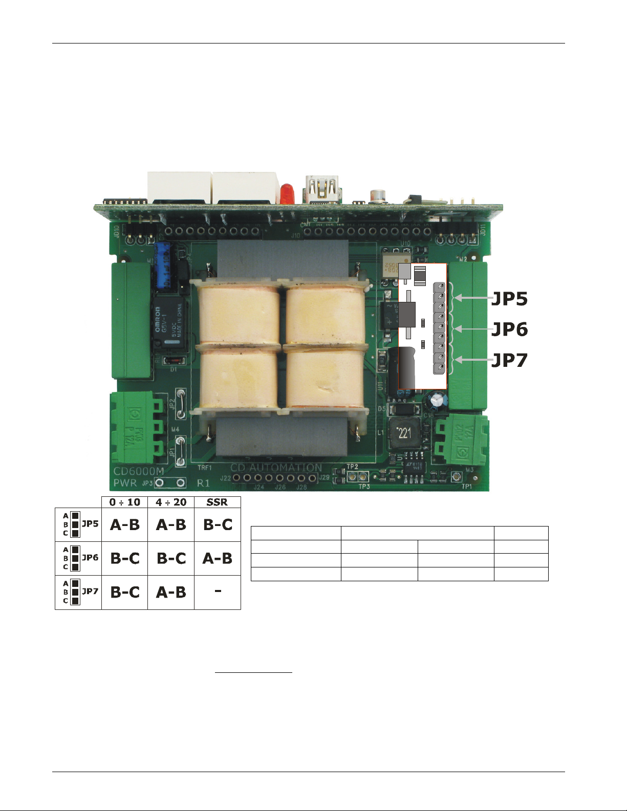
The primary input is already configured in line with customer requirements that are defined in the Order
Code. The Order Code is written on the identification label.
However, if you wish to change the primary input (ex. from 0÷10V to 4÷20mA) proceed as follows:
A
B
C
A
B
C
A
B
C
Type Input features Jumper
0÷10V (default) Impedance 15KΩ Open
POT Impedance 10KΩ min Open
4÷20mA Impedance 100Ω Close
Primary Input calibration procedure
When you change the hardware setting is necessary make the Input calibration procedure.
To make the Input calibration procedure follow these steps:
• Give the power supply.
• With Control Panel go in the Hardware menu ( = 5)
• Set the input signal to the min value (ex. 0V for 0÷10V or 4mA for 4÷20mA)
• Set the parameter = 1
• Press ENTER key
• Set the input signal to the max value (ex.10V for 0÷10V or 20mA for 4÷20mA)
• Set the parameter = 1
• Press ENTER key
The Input calibration procedure is done.
REVO_M08
34
Page 35
CD Automation srl REVO M User’s Manual
18 PG Connector
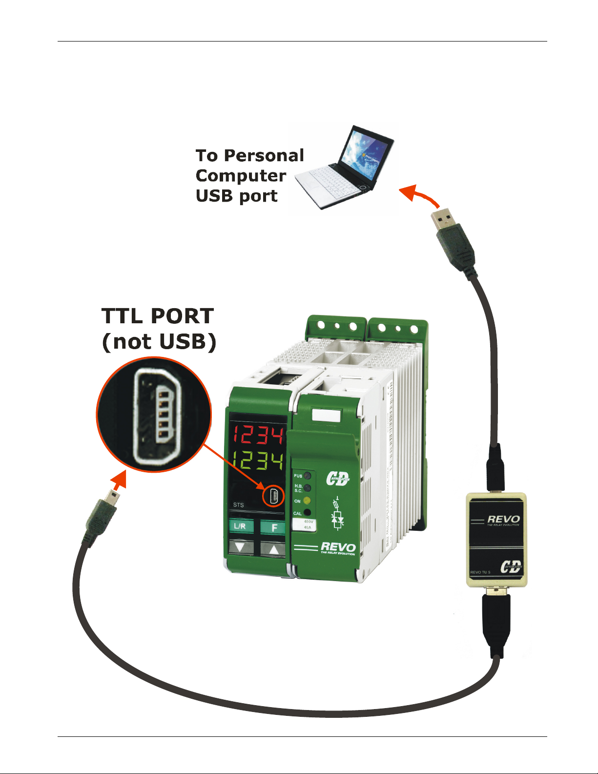
The PG Connector is used to configure the thyristor unit with the configuration software and with the
programming cable.
The programming cable is not included.
REVO_M08
35
Page 36
CD Automation srl REVO M User’s Manual
19 RS485 Serial Port
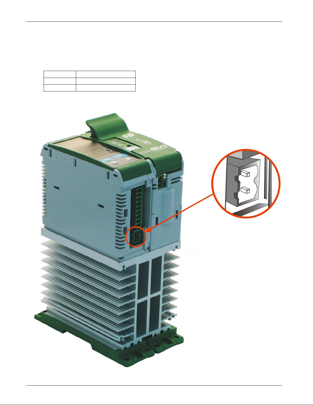
The serial communication port RS485 is available on the Command Terminals and on the 9pin DIN male
connector.
On this port may be done a network up to 127 REVO M.
On the 9pin DIN male connector is also possible connect the CD-EASY
Terminal Description
A+ RS485 A
B- RS485 B
REVO_M08
36
Page 37
CD Automation srl REVO M User’s Manual
20 MODBUS communication
The serial communication port of the thyristor unit is two-wire RS485 type.
This port use an half-duplex system.
When a Unit must transmit active the transmission line, and when there are not units in transmission
the outputs are fixed to high impedance.
The serial communication port allows to communicate between the thyristor units and a MASTER device
(ex. an computer or a terminal). The cable must be rated for use to data transfer
20.1 MODBUS RTU Protocol
The communication is based on the standard industrial MODBUS RTU with the following restrictions:
• The Baud rate can be 4800-9600-19200 Baud (Standard 19200).
• The Preset Multiple Registers (Funct. 16) is limited to the writing of a single parameter
The following MODBUS functions are supported:
20.2 Message Format
for message.
Function Description
03 Read Holding Registers
16 Preset Multiple Registers
The unit support the Broadcast messages:
It' possible send a Broadcast messages using the address 0, all the units respond at the
message without sending back any reply.
The transmission format is a 1 bit start, 8 date bit, and 1 bit stop with no parity verification.
Each message terminate after a said time of "time out", equal at 3.5 time of a character transmission,
where there are not transitions on the transmission line.
The first Byte of each message is always the address of the unit that is a value from 1 to 255 or 0 for
the broadcast messages, the second is always the function number, and the rest of the message
depends of the function demand.
When a Slave receive an message, the unit send an answer with the same structure but
with the information demanded.
Each message is followed by CRC (Cyclic Redundancy Check) with two byte. The CRC identify the
incongruity situations of the message, in this case the receiver ignore the message.
The CRC is calculated in accordance with a formula that imply a recursive division of the data by a
polynomial.
The polynomial divisor is:
216 + 215 + 22 + 1(Hex 18005)
but is modified in two ways:
• Since the bits order are reversed, then the binary pattern is also reversed, and the most significant
bit (MSB) is the right-most bit.
• Since interest only the remainder, the right-most bit could be discarded.
Therefore, the polynomial divisor has value: Hex A001
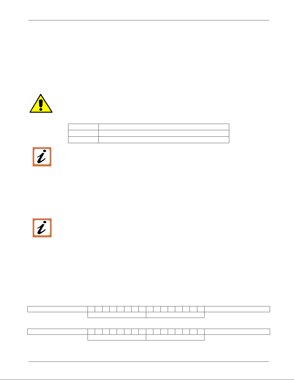
Normal bit order:
Most significant bit Least significant bit
Most significant Byte Least significant Byte
Reversed bit order:
Least significant bit Most significant bit
Least significant Byte Most significant Byte
N.B.: With the reversed bit order, also the CRC16 returns the with the reversed bit order
REVO_M08
37
Page 38
CD Automation srl REVO M User’s Manual
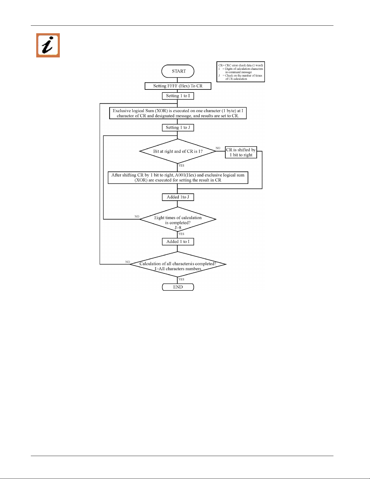
The following flow-diagram show how to organize the CRC 16 bit.
C Language CRC 16 Example
static short CRC16 (unsigned char *p_first,unsigned char *p_last)
{
unsigned int crc=0xffff;
short j;
for (;p_first<=p_last;p_first++)
{
crc ^= *p_first;
for(j=8;j>0;j--)
{
if(crc & 0x0001)
{
crc = crc >> 1;
crc ^= 0xA001;
}
else
{
crc = crc >> 1;
}
}
}
return (crc);
}
REVO_M08
38
Page 39
CD Automation srl REVO M User’s Manual
20.3 Read Holding Registers
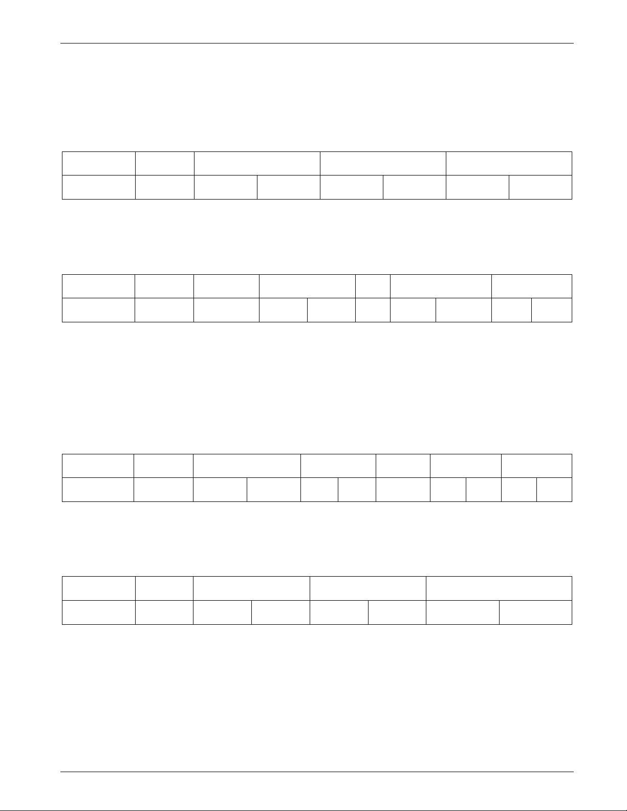
This function reads the instantaneous value of a specified number of parameters from an address.
The message is composed by 8 Byte: one Byte is for the address, one for the function (03 Hex), two
Byte for the first parameter to read, two Byte for the total number of parameters to read and finally two
Byte for the CRC:
Address
Unit
The answer is an echo of the first two Byte (address and function), one byte with the number of
following byte to exclusion of the CRC, the demanded values and finally two Byte for the CRC:
Address
Unit
Function
3
3Hex
Function
3
3Hex
Address of the First
Parameter
HI LO HI LO LO HI
N° of
Byte
HI LO … HI LO LO HI
First Parameter
Value
N° of the Parameter CRC 16
Last parameter
value
CRC 16
20.4 Preset Multiple Registers
This function could write only a parameter for each message.
The message is composed by 11 Byte: one Byte for the address, one for the function (10 Hex), two Byte
for first parameter to write, two Bytes for the N° of parameters, fixed to 1 (0001 Hex), one Byte with
the number of following Bytes, fixed to 2 (02 Hex), two Byte for the CRC:
Address
Unit
The answer is an echo of the first two Byte (address and function), two Byte for first written parameter,
two Byte with the N° of parameters, fixed to 1 (0001 Hex), two Byte for the CRC:
Address
Unit
Function
16
10Hex
Function
16
10Hex
Address of the
First Parameter
HI LO 0 1 2 HI LO LO HI
Address of the First
Parameter
HI LO 0 1 LO HI
N° of the
Parameter
N° of the
Parameter
N° of
Byte
Value to
write
CRC 16
CRC 16
REVO_M08
39
Page 40
CD Automation srl REVO M User’s Manual
20.5 Error and exception responses
If a message contains an altered character, if fails the CRC, or if the received message contains a syntax
error (for example the number of the byte or of the words is not correct), then the unit will ignore the
message.
If the received message is correct but contains a not valid value, the unit will send an answer of
exception (5 byte):
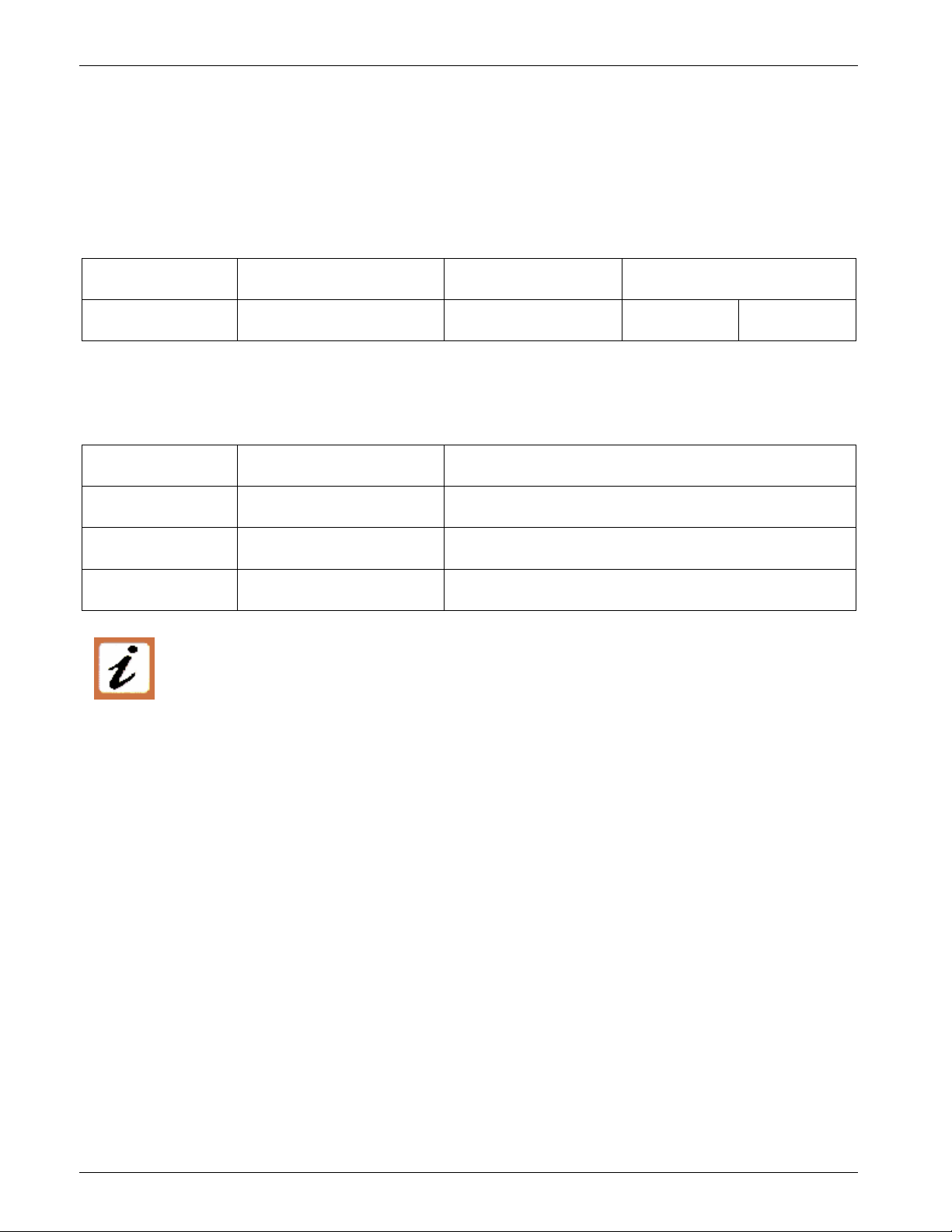
Address Unit Function Error Code CRC 16
LO HI
The byte with the function number, represent the function number of the message that has caused the
error with the first Bit set to 1 (ex. the function 3 becomes 0x83) The error code could be one of the
followings:
Error Code Name Cause
1 ILLEGAL FUNCTION Function not supported.
2 ILLEGAL DATA ADDRESS Address out of range.
3 ILLEGAL DATA VALUE Attempt to write invalid or action not carried out.
NOTE: If you write a parameter's value equal at his actual value this is a valid transaction
and don't cause an error.
20.6 Address Configuration
The thyristor unit is assigned a unique device address by the user in the range 1 (default) to
127 using the parameter P115 in the Hardware menu. This address is used to recognise the
messages queries to her assigned.
The thyristor unit does not respond at the messages queries that don't have the same assigned address.
The thyristor unit will also accept global messages (Broadcast) sends at the address 0. No responses are
returned for globally addressed queries.
REVO_M08
40
Page 41

CD Automation srl REVO M User’s Manual
21 Configuration Parameters
The Configuration Parameters are accessible from the Control Panel (place in front of unit), from the
software configurator or through the serial communication port RS485.
With the RS485 Serial Port the parameters are not divided by menu, but only by numerical order.
P010 (H0A)
Function: This parameter show the Average voltage output on the three phases.
Min/Max: 0 ÷ 1023 (0 ÷ 3FF Hex)
Value: from 0 = 0V,
Default: Example: 220V is equal to read value 220
Note: -
P011 (H0B)
Function: This parameter shows the RMS current present on the power terminal L1.
Min/Max: 0 ÷ 1023 (0 ÷ 3FF Hex)
Value: from 0 = 0A,
Default: Example: 45A is equal to read value 450 with decimal point P040 settings = 1
Note: -
P012 (H0C)
Function: This parameter shows the Average power output on the three phases.
Min/Max: 0 ÷ 1023 (0 ÷ 3FF Hex)
Value: from 0 = 0%,
Default: Example: Note: -
P013(H0D) Status Table R
Function: It’s a tab in bit that represent the “Status” of thyristor unit
Value:
Average voltage output V R
To 1023 =1023V.
Current output A R
To 1023 =102,3 A. for unit up to 90A
from 0 = 0A,
To 1023 =1023A.
450A is equal to read value 450 with decimal point P040 settings = 0
Power output % R
To 1023 =100%.
Bit 0 = 1 -> Short circuit on SCR
= 0 -> NO short circuit on SCR
Bit 1 = 1 -> Load Failure (HB Alarm)
= 0 -> NO Load Failure (HB Alarm)
Bit 2 = 1 -> Output signal ON
= 0 -> Output signal Off
Bit 3 = 1 -> HB Calibration in progress
= 0 -> NO HB Calibration in progress
Bit 4 = not used.
Bit 5 = 1 -> Heat sink over temperature
= 0 -> NO HB Heat sink over temperature
Bit 6 = not used
Bit 7 = not used
Bit 8 = 1 -> Digital input 1 closed
= 0 -> Digital input 1 open
Bit 9 = 1 Digital input 2 closed
= 0 -> Digital input 2 open
REVO_M08
41
Page 42
CD Automation srl REVO M User’s Manual
OUT %
P014 (H0E) Command Table R/W
Function: It’s a tab in bit for remote commands via RS485
Value:
Bit 0 = 0 not used
Bit 1 = 1 -> Setpoint Digital (see P015, (Only with DI1 or DI2 not 3)
= 0 -> Setpoint Analog (see P015, (Only with DI1 or DI2 not 3)
Bit 2 = 1 -> Enable Output signal (Only with DI1 or DI2 not 1)
= 0 -> Disable Output signal (Only with DI1 or DI2 not 1)
Bit 3 = 1 -> Reset HB Alarm
Note: When unit nis switch off all command parameter are set to 0
P015 (H0F)
Function:
Digital Set Poin % R/W
This parameter reads the Input command signal
When the P004 Bit1 =1 This parameter could be written and become the Input
Command from RS485
Min/Max: 0 ÷ 1023 (0 ÷ 3FF Hex)
Value: from 0 = 0%,
To 1023 =100,0%.
Default: Example: Input 4mA -> P005L = 0 (0%)
Input 12mA -> P005L = 512 (50%)
Input 20mA -> P005L = 1023 (100%)
Note: -
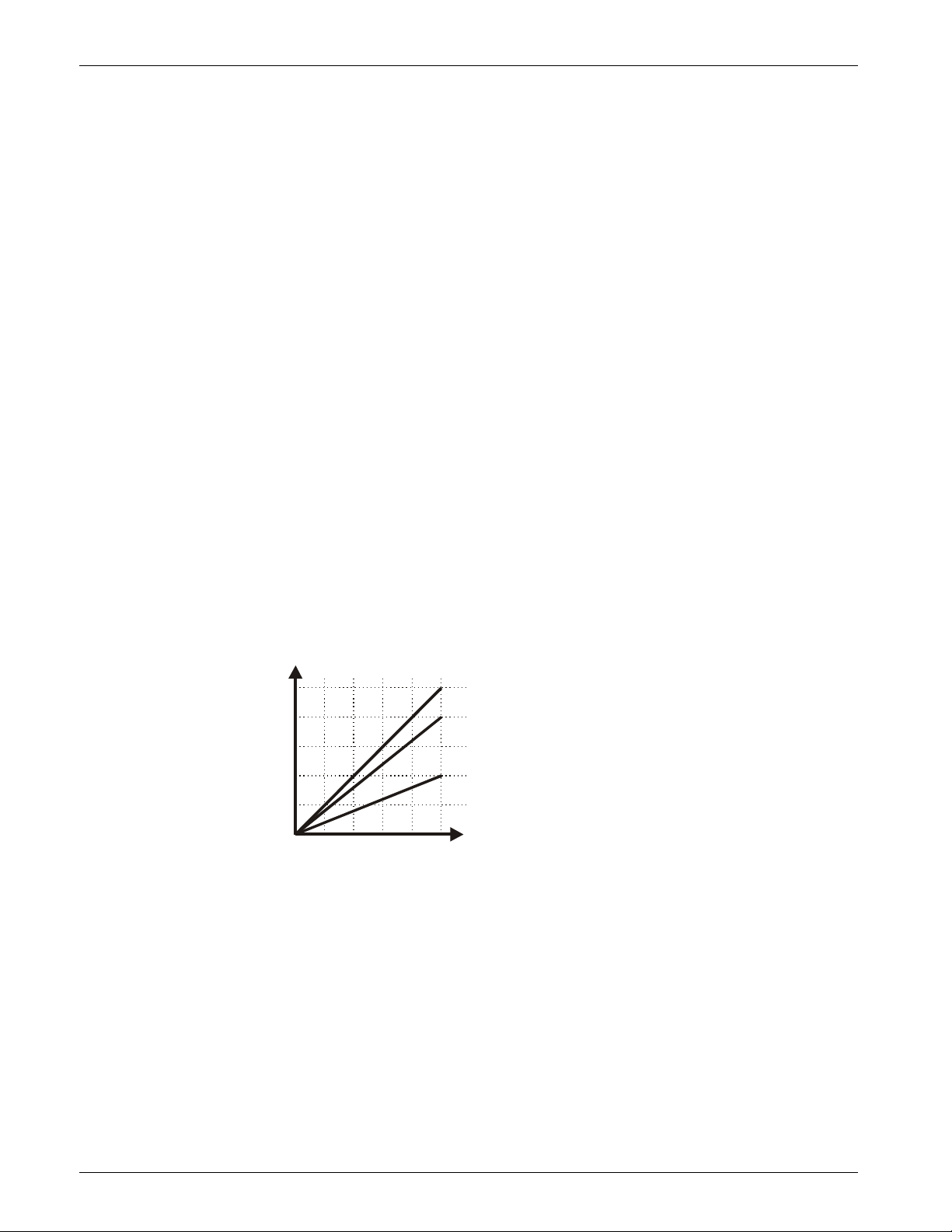
P016 (H10)
Maximum output % R/W
Function: Its’ a scaling factor of the Input command signal
Min/Max: 0 ÷ 255 (0 ÷FF Hex)
Value: from 0 = 0% of Output,
To 255 = 100% of Output.
Default: Example: Note: This parameter limit the Output Power
100
80
60
40
20
0
4020 60 10080
Power Adjust = 100%
Power Adjust = 80%
Power Adjust = 40%
Input %
P018 (H12)
Firing Type R/W
Function: This parameter selects the Firing Type.
Min/Max: Value: 0= BURST firing mode
1= PHASE ANGLE mode
2= DELAY TRIGGERING mode
Default: 1 (if not specified in the Order Code)
Example: Note: -
REVO_M08
42
Page 43

CD Automation srl REVO M User’s Manual
P019 (H13)
Feed back selection R/W
Function: This parameter selects the Feed-back type.
Min/Max:
Value: 0 = Current feed-back (rms value)
1 = Voltage feed-back (rms value)
2 = Power feed-back VxI
3 = None feed-back
Default: 1 (if not specified in the Order Code)
Example:
Note: Feed-back value is the average value on the three phase R, S, T
P020 (H14)
Function:
Burst Firing Cycles (Not used in PHASE ANGLE) Cycles R/W
It defines the number of voltage cycles in ON condition at 50% of power
demand
Min/Max: 1 ÷ 255 cycles
Value: Default: 8 (if not specified in the Order Code)
Example: Note: -
P022 (H16)
Delay triggering ° R/W
Function: This parameter set firing delay in °
Min/Max: 0 ÷ 255 (0 ÷FF Hex)
Value: from 0 = 0°,
To 255 = 100°.
Default: 0
Example: Note: -
P023 (H17)
Function:
Sofstart - Ramp Up R/W
This parameter have two functions: if the firing mode is Phase Angle de P023 is
Time to reach the full angle of firing.
The Unit starts in phase angle mode with a ramp starting from zero up to full
voltage in a presetted and Adjustable time.
The time is setted by this parameter
Min/Max: Value: Default: Example: Note: -
Function:
Sofstart - Ramp Cycles of Burst Cycles R/W
If the firing is Burst Firing this parameter set the number of cycle.
In Burst Firing is possible to have a soft start ramp.
With this parameter you can define how much cycles are necessary to reach
the complete wave form. You must set a value between 0 and the number of
cycles setted in the parameter P083 . If you set 0 value the ramp is
disabled
Min/Max:
Value: 0 ÷ 100 cycles
Default: 4 (with firing S+BF) 0 (wit other firing)
Example: -
Note: -
REVO_M08
43
Page 44
CD Automation srl REVO M User’s Manual
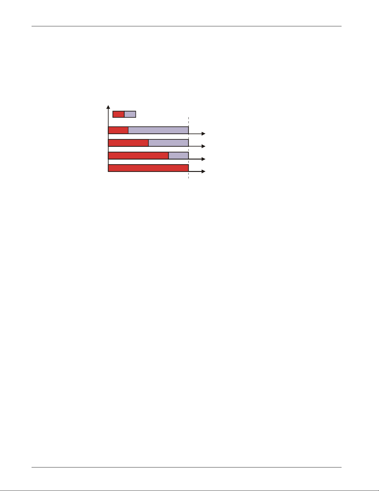
Cycle Time
P024 (H18)
Cycle time % R/W
Function: The Cycle Time is the time which the Thyristor modulates to obtain the power
demand
Min/Max: 0 ÷ 255 (0 ÷ FF Hex)
Value: Each step is 50msec
Default: 60 (3C Hex) = Zero Crossing
240 (F0 Hex) = Burst Firing
Example: With a Cycle time at 4 sec:
25%-> 1sec 0n+3sec off
50%-> 2sec 0n+2sec off
75%-> 3sec 0n+1sec off
ON OFF
25%
50%
75%
100%
Time
Note: -
P026 (H1A)
Proportional Band % R/W
Function: This parameter is the gain of the feed-back loop
Min/Max: 0 ÷ 255 (0 ÷FF Hex)
Value: 0 ÷ 255
Default: VxI or V2 = 5 Hex
V or I =12 Hex
Example: Note: This parameter increase the loop speed but decrease the loop stability.
P027 (H1B)
Integral Time % R/W
Function: This parameter is the integral time of the feed-back loop
Min/Max: 0 ÷ 255 (0 ÷FF Hex)
Value: Default: 50 Hex
Example: Note: If you increase integral time you increase the output stability, but you increase
also the time to reach the set.
P028 (H1C)
HB delay Sec R/W
Function: This parameter set a delay to have HB alarm active
Min/Max: 0 ÷ 255 (0 ÷FF Hex)
Value:
Default:
Example:
Note:
P029 (H1D)
Function:
HB sensitivity % R/W
This parameter defines the threshold of resistance that activates the HB alarm
This value is in percentage respect the nominal resistance load value
Min/Max: 0,0 ÷ 100,0%
Value: Default: 100,0
Example:
……. =20. This means that the Heather Break Alarm became active when
the current goes below 80A
Note: -
REVO_M08
44
Page 45

CD Automation srl REVO M User’s Manual
P030 (H1E)
Baud Rate R/W
Function: This parameter selects the Baud rate on the serial port.
Min/Max:
Value: 0 = 4800
1 = 9600
2 = 19200
Default: 2
Example: Note: -
P031 (H1F)
Address R/W
Function: This parameter selects the Address on the serial port for the thyristor unit.
Min/Max: 1 ÷ 127
Value: Default: 1
Example: Note: -
P032 (H20)
Digital input 1 configuration R/W
Function: This parameter selects the function of digital input.
Min/Max: Value: 0 = Additional Reset Alarm
1 = Setpoint Zero
2 = Feed-back Selection
3 = Setpoint Analog/Digital
4 = External Alarm
Default: 1
Example: Note: -
P033 (H21)
Digital input 2 configuration R/W
Function: This parameter selects the function of digital input.
Min/Max: Value: 0 = Additional Reset Alarm
1 = Setpoint Zero
2 = Feed-back Selection
3 = Setpoint Analog/Digital
4 = External Alarm
Default: 1
Example: Note: -
P034 (H22)
Digital output 1 configuration R/W
Function: This parameter selects the function of digital input.
Min/Max: Value: 0 = Additional Reset Alarm
1 = Setpoint Zero
2 = Feed-back Selection
3 = Setpoint Analog/Digital
4 = External Alarm
Default: 1
Example: Note: -
REVO_M08
45
Page 46

CD Automation srl REVO M User’s Manual
P037 (H25)
Operative Load Voltage V R/W
Function: This parameter is used to set in volt the operative voltage of the load.
Min/Max: 0 ÷ 1023 (0 ÷ 3FF Hex)
Value: from 0 = 0V,
To 1023 =1023V.
Default: 0
Example: Note: -
P038 (H26)
Load nominal Current A R/W
Function: This parameter is used to set the Load nominal Current.
Min/Max: from 0 = 0A,
To 1023 =102,3 A. for unit up to 90A
from 0 = 0A,
To 1023 =1023A. for unit over 90A
Value: Default: Max Current of REVO M (if not specified in the Order Code)
Example: Size of REVO M (Max Current) : 100A
Load nominal Current: 50A
P119 =50.0
Note: This parameter is necessary to have the correct rescaling inside the unit. For
this reason it's very important specify this value in the order code.
P044 (H2C)
Input type V R/W
Function: Input type selection.
Min/Max: 0 ÷ 255
Value:
Default:
Example:
Note:
P045 (H2D)
Load Type R/W
Function: This parameter set firing delay in °
Min/Max:
Value:
0=star
1=star+N
2=delta
3=open delta
Default: 0 (if not specified in the Order Code)
Example: Note: -
REVO_M08
46
Page 47

CD Automation srl REVO M User’s Manual
omer’s cost and our Service will evaluate
22 Maintenance
In order to have a corrected cooling, the user must clean the heat-sink and the protective grill of the
fans. The frequency of this servicing depends on environmental pollution.
Also check periodically if the screw for the power cables and safety earth are tightened correctly
(See Connection Diagram)
22.1 Trouble Shooting
Small problems sometimes can be solved locally with the help of the below tab of trouble shooting.
If you don’t succeed, contact us or your nearest distributor.
Symptom
Load current
doesn’t flow
Load current flow
also without input
signal
Current flows at
nominal value but
Yellow LED
(HB/SC) is light
on
Indication on
front unit
Green LED (ON)
light OFF
Green LED (ON)
light ON
Red LED (SC)
light on
Yellow LED (HB)
light on
or
Red LED (SC)
light on
Possible reasons of the
symptom
• No Auxiliary Voltage
• No input signal
• Reversed polarities of input
signal
• Fuse failure
• Load connection interruption
• Load failure: The yellow led (HB)
is light on (with HB option)
• Thyristor fault: The red led (SC)
is light on (with HB option)
• Wrong wiring
• SCR short circuit
• HB circuit not tuned
• Current transformers not
properly wired
Actions
• Give auxiliary voltage supply
(See Connection Diagram)
• Provide to give input signal
• Reverse the input signal polarity
• Change the fuse
• Check the wiring
• Check the load
• Change the thyristor module
• Check the wiring
• Change the thyristor module
• Make HB calibration procedure
• Check current transformers
wiring
Thyristor unit
doesn’t work
properly
22.2 Warranty condition
CD Automation gives a 12 months warranty to its products.
The warranty is limited to repairing and parts substitution in our factory and does
exclude products not properly used and fuses.
Warranty does not include products with serial numbers deleted. The faulty product
should be shipped to CD Automation at cust
if product is under warranty terms.
Substituted parts remain of CD Automation property.
REVO_M08
• Auxiliary voltage supply out of
limits
• Wrong input signal selection.
• Wrong input signal calibration
(out of range)
47
• Verify the auxiliary voltage
supply
• Control input signal setting.
• Check input setting
Page 48

CD Automation srl REVO M User’s Manual
REVO_M08
48
 Loading...