

Page 1
CD Automation Communication Manual Revo C
1
REVO C
Serial Communication
Manual
USER’S MANUAL
Rev. 12/2018
Preliminary
0011
Page 2

CD Automation Communication Manual Revo C
2
Sommario
1 MODBUS-RTU communication protocol .......................................................................... 3
Communication Terminals 30-40A (SR9-SR10-SR11) 3
1.1.1 RS485 STANDARD SERIAL PORT ......................................................................................................................................... 3
1.1.2 SECOND SERIAL 485 CONFIGURATION CONNECTORS ......................................................................................................... 3
1.2 Communication Terminals 60-210A(From SR12 to SR17) 4
1.2.1 RS485 SERIAL PORT ........................................................................................................................................................... 4
1.2.2 SECOND SERIAL 485 CONFIGURATION CONNECTORS ......................................................................................................... 4
1.3 Communication Terminals 300-700A (S12-S13-S14) 5
1.3.1 RS485 SERIAL PORT ........................................................................................................................................................... 5
1.4 Fieldbus communication option 5
1.5 MODBUS communication 6
1.6 MODBUS RTU Protocol 6
1.7 Message Format 6
1.8 Read Holding Registers(function 03 / 03Hex) Read InputRegisters (function 04 / 04Hex) 8
1.9 Preset Multiple Registers (function 16/ 10Hex) 9
1.10 Preset single register (function 06/ 06Hex) 9
1.11 Error and exception responses 10
1.12 Address Configuration 10
1.13 Parameter List 11
2 Fieldbus....................................................................................................................... 20
2.1 MODBUS/TCP 21
2.1.1 GENERAL DESCRIPTION ..................................................................................................................................................... 21
2.1.2 PROFINET CONNECTION ................................ ................................ ................................................................ ................. 21
2.1.3 MODBUS/TCP PROTOCOL .............................................................................................................................................. 22
2.1.4 PLC/DEVICE CONFIGURATION.......................................................................................................................................... 22
2.1.5 INSTRUMENT IP SETTING .................................................................................................................................................. 23
2.2 PROFINET 26
2.2.1 GENERAL DESCRIPTION ..................................................................................................................................................... 26
2.2.2 PROFINET CONNECTION ................................ ................................ ................................................................ ................. 26
2.2.3 PLC CONFIGURATION ....................................................................................................................................................... 28
2.3 PROFIBUS 32
2.3.1 GENERAL DESCRIPTION ..................................................................................................................................................... 32
2.3.2 PROFIBUS CONNECTION ................................ ................................................................................................ ................. 32
2.3.3 PLC CONFIGURATION ....................................................................................................................................................... 34
2.4 Data Exchange Area 36
2.4.1 READ AREA ....................................................................................................................................................................... 36
2.4.2 WRITE AREA ..................................................................................................................................................................... 42
Page 3
CD Automation Communication Manual Revo C
3
1 MODBUS-RTU communication protocol
Communication Terminals 30-40A (SR9-SR10-SR11)
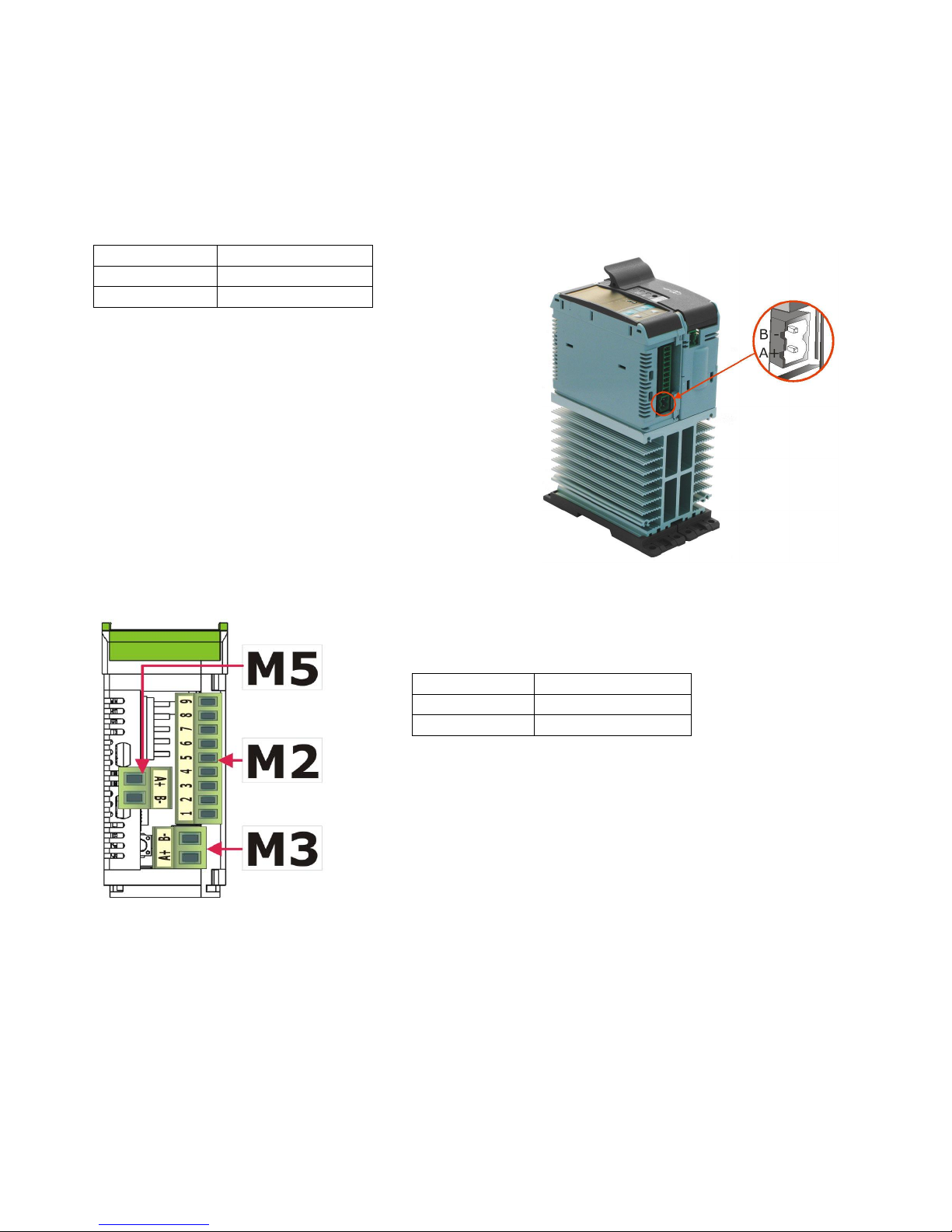
1.1.1 RS485 standard Serial Port
M3 Terminal
Description
B-
RS485 B
A+
RS485 A
The serial communication port RS485 is
available on the Command.
On this port may be done a network up to 127
REVO C.
1.1.2 Second Serial 485 Configuration Connectors
M5 Terminal
Description
A+
RS485 A
B-
RS485 B
Page 4
CD Automation Communication Manual Revo C
4
1 2 3 4 5
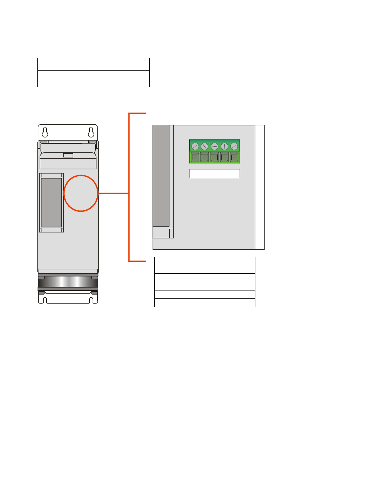
1.2 Communication Terminals 60-210A(From SR12 to SR17)
1.2.1 RS485 Serial Port
The serial communication port RS485 is available on the
Command.
On this port may be done a network up to 127 REVO C.
M1 Terminal
Description
11
RS485 A+
12
RS485 B-
1.2.2 Second Serial 485 Configuration Connectors
M4
Description
1
+24V
2
GND
3
Not connected
4
RS485 A+
5
RS485 B-
Page 5
CD Automation Communication Manual Revo C
5
1.3 Communication Terminals 300-700A (S12-S13-S14)
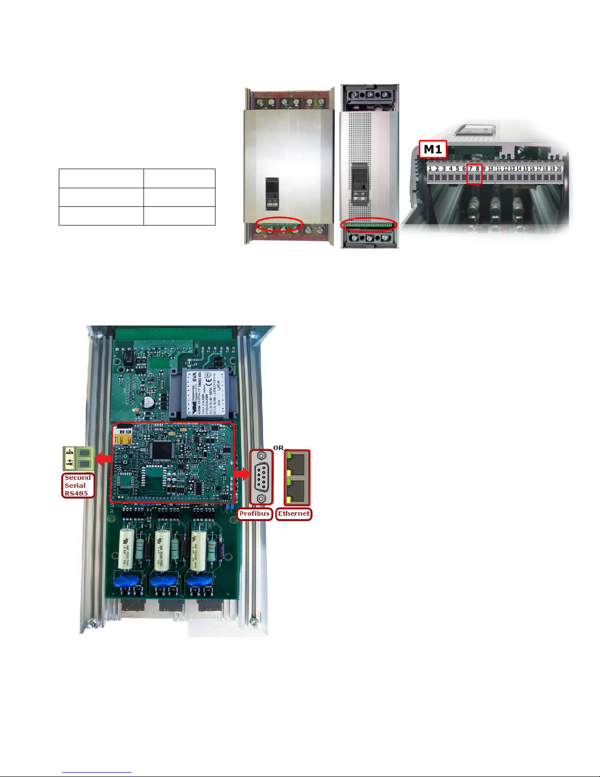
1.3.1 RS485 Serial Port
The serial communication port RS485
is available on the Command Terminals.
On this port may be done a network
up to 127 REVO C.
Terminal M1
Description
7
RS485 A
8
RS485 B
1.4 Fieldbus communication option
Other serial communication port are available as option.
Page 6
CD Automation Communication Manual Revo C
6
1.5 MODBUS communication
The serial communication port of the thyristor unit is two-wire RS485 type.
This port use an half-duplex system.
When a Unit must transmit active the transmission line, and when there are not units in
transmission the outputs are fixed to high impedance.
The serial communication port allows to communicate between the thyristor units and a MASTER
device (ex. an computer or a terminal). The cable must be rated for use to data transfer
1.6 MODBUS RTU Protocol
The communication is based on the standard industrial MODBUS RTU with the following
• The Baud rate can be 9600-19200-38400-115200 Baud (Standard 19200).
• The Preset Multiple Registers (Function 16) is limited to the writing of a single
parameter for message.
The following MODBUS functions are supported:
Function
Description
03/04
Read Holding Registers (max 121 reg.)
06
Preset Single Registers
16
Preset Multiple Registers (max 25 reg.)
The unit support the Broadcast messages:
It' possible send a Broadcast messages using the address 0, all the units respond at
the message without sending back any reply.
1.7 Message Format
The transmission format is a 1 bit start, 8 date bit, and 1 bit stop with no parity verification.
Each message terminate after a said time of "time out", equal at 3.5 time of a character
transmission, where there are not transitions on the transmission line.
The first Byte of each message is always the address of the unit that is a value from 1 to 255 or 0
for the broadcast messages, the second is always the function number, and the rest of the
message depends of the function demand.
When a slave receives a message, the unit sends an answer with the same structure
but with the information requested.
Each message is followed by CRC (Cyclic Redundancy Check) with two bytes. The CRC identifies
the incongruity situations of the message, in this case the receiver ignores the message.
The CRC is calculated in accordance with a formula that implies a recursive division of the data by
a polynomial.
The polynomial divisor is:
216 + 215 + 22 + 1(Hex 18005)
but is modified in two ways:
• Since the bits order are reversed, then the binary pattern is also reversed, and the most
significant bit (MSB) is the right-most bit.
• Since interest only the remainder, the right-most bit could be discarded.
Therefore, the polynomial divisor has value: Hex A001
Page 7
CD Automation Communication Manual Revo C
7
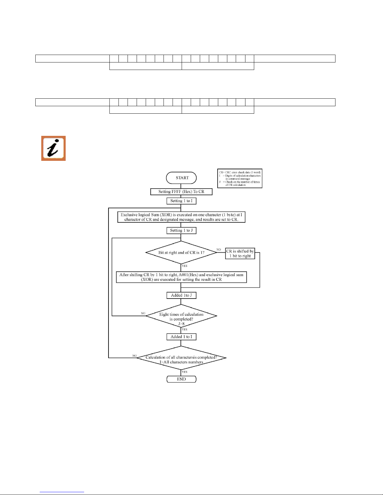
Normal bit order:
Most significant bit
Least significant bit
Most significant Byte
Least significant Byte
Reversed bit order:
Least significant bit
Most significant bit
Least significant Byte
Most significant Byte
N.B.: With the reversed bit order, also the CRC16 returns the with the reversed bit order
The following flow-diagram shows how to organize the CRC 16 bit.
Page 8

CD Automation Communication Manual Revo C
8
C Language CRC 16 Example
static short CRC16 (unsigned char *p_first,unsigned char *p_last)
{
unsigned int crc=0xffff;
short j;
for (;p_first<=p_last;p_first++)
{
crc ^= *p_first;
for(j=8;j>0;j--)
{
if(crc & 0x0001)
{
crc = crc >> 1;
crc ^= 0xA001;
}
else
{
crc = crc >> 1;
}
}
}
return (crc);
}
1.8 Read Holding Registers(function 03 / 03Hex)
Read InputRegisters (function 04 / 04Hex)
This function reads the instantaneous values of a specified number of parameters from an address.
The message is composed by 8 Byte:
• one Byte is for the address
• one for the function (03/04Hex)
• two Byte for the address of the first parameter to read
• two Byte for the total number of parameters to read (max 121)
• two Byte for the CRC
Address
Unit
Function
Address of the First
Parameter
N° of read
Parameter
CRC 16
3/4
3/4Hex
HI
LO
HI
LO
LO
HI
The answer is an echo of the first two Byte (address and function), one byte with the number of
byte following (CRC excluded), the demanded values and finally two Byte for the CRC.
Address
Unit
Function
N° of
Byte
First
Parameter
Value
Last
Parameter
Value
CRC 16
3/4
3/4Hex
2 - 32
HI
LO LO
HI
LO
HI
Page 9

CD Automation Communication Manual Revo C
9
1.9 Preset Multiple Registers (function 16/ 10Hex)
This function could write maximum 25 parameters for each message.
The message is composed by:
• one Byte for the address
• one for the function (10 Hex)
• two Byte for first parameter address to write
• two Bytes for the N° of parameters
• one Byte with the number of following Bytes
• values to write, two Byte for the CRC:
Address
Unit
Function
Address of the
First Parameter
N° of the
Parameter
N° of
Byte
Value to
write
→
16
10Hex
HI
LO
HI
LO 2 HI
LO
→
→
First value
To write
Last value
To write
CRC 16
→
HI
LO HI
LO
LO
HI
The answer is an echo of the first two Byte (address and function), two Byte for first written
parameter, two Byte with the N° of parameters, fixed to 1 (0001 Hex), two Byte for the CRC.
Address
Unit
Function
Address of the
First Parameter
N° of the
Parameter
CRC 16
16
10Hex
HI
LO 0 1
LO
HI
1.10 Preset single register (function 06/ 06Hex)
This function writes a single Modbus paramter.
The message is composed by 8 Bytes:
• one Byte for the address,
• one for the function (6 Hex),
• two Bytes for the parameter address to write
• two bytes for the value to write
• two Bytes for the CRC
Address
Unit
Function
Address of the
First Parameter
Value to Write
CRC 16
6
6Hex
HI
LO
HI
LO
LO
HI
The normal response is a complete echo of the received message.
Page 10

CD Automation Communication Manual Revo C
10
1.11 Error and exception responses
If a message contains an altered character, if fails the CRC, or if the received message contains a
syntax error (for example the number of the byte or of the words is not correct), then the unit will
ignore the message.
If the received message is correct but contains a not valid value, the unit will send an answer of
exception (5 byte):
Address Unit
Function
Error Code
CRC 16
LO
HI
The byte with the function number, represent the function number of the message that has caused
the error with the first Bit set to 1 (ex. the function 3 becomes 0x83) The error code could be one
of the followings:
Error Code
Name
Cause
1
ILLEGAL FUNCTION
Function not supported.
2
ILLEGAL DATA ADDRESS
Address out of range.
4
FAILURE IN
ASSOCIATED DEVICE
Too Many parameter request
1.12 Address Configuration
The thyristor unit is assigned a unique device address by the user in the range 1 (default) to
247 using the parameter P115 in the Hardware menu. This address is used to recognize the
messages queries to her assigned.
The thyristor unit does not respond at the messages queries that don't have the same assigned
address.
Page 11

CD Automation Communication Manual Revo C
11
1.13 Parameter List
Par
Min
Max
Min UM
Max UM
UM
Write
Enable
Access
Level
1PH
2/3 PH
Description
1 0 65535
X 0
X
X
Change user access level
Level 0
Par 1 = 0
Level 1
Par 1 = 1111 (dec)
Level 2
Par 1 = 2222 (dec)
Level 3
Par 1 = 3333 (dec)
2 0 1 1 X
X
Used to temporarily disable Field
Communications 0:Enabled 1: Disabled
3 0 X
X 4 0 X
X
5 0 X
X
Displays which hilscher module is populated
6 x 0 X
X
Used to specify if your secondary port is
used for WiFi/2nd Modbus or Hilscher/LOG
7 0 9999
-
X
X
Used for factory reset (wipes all EEPROM
except serial number) of system or USB
tunnel to Hilscher or Wifi
8 0 65535
X 3
X
X
Used to save or restore default
configuration
9 0 65535
0
655,35
Hz 0
X
X
Main network frequency
10 0 1023
0
1023
V 0
X
X
Rms Voltage or average Voltage of rms for
multi-phase
11 0 1023
0,0
102,3
A 0
X
X
RMS Current or Average RMS Current
(multi-phase)
12 0 1023
0
1023
% 0
X
X
RMS Power or Average RMS Power
(multi-phase)
Page 12
CD Automation Communication Manual Revo C
12
Par
Min
Max
Min UM
Max UM
UM
Write
Enable
Access
Level
1PH
2/3 PH
Description
13 0 1023
0
1023
Sw 0
x
x
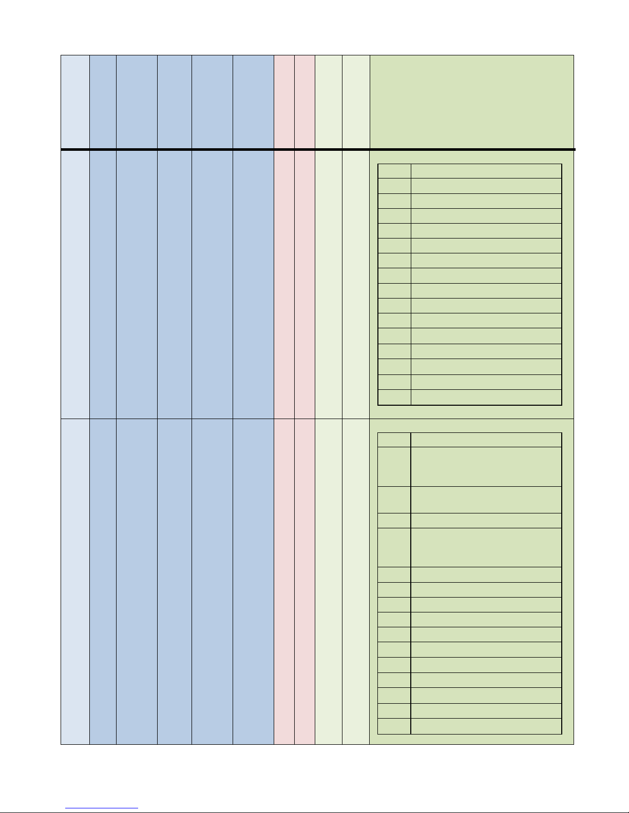
Status bitmask
bit0
ShortCut Alarm
bit1
Heat Break Alam
bit2
ON/OFF unit
bit3
Not used
bit4
Current Limit Alarm
bit5
Therma Alarm
bit6
Communication Alarm ( WD)
bit7
Not used
bit8
Digital input 1 status
bit9
Digital input 2 status
bit10
Not used
bit11
Not used
bit12
Not used
bit13
Not used
bit14
Not used
bit15
intervento allarme termico
14 0 255
0
1023
Sw X 0
X
0
Command bitmask
bit0
Not used
bit1
Digital Reference
0= from analogue input
1= from communication/keyb.
bit2
Unit enable
1= Enable 0= Disable
bit3
Not used
bit4
Current Limit Switch
0= from analogue input
1= from communication/keyb.
bit5
Not used
bit6
Save Factory
bit7
Load Factory
bit8
Not used
bit9
Not used
bit10
Not used
bit11
Not used
bit12
Not used
bit13
Not used
bit14
Not used
bit15
Not used
Page 13
CD Automation Communication Manual Revo C
13
Par
Min
Max
Min UM
Max UM
UM
Write
Enable
Access
Level
1PH
2/3 PH
Description
15 0 1023
0,0
100,0
% X 0
X
X
Remote set point for unit
16 0 255 0 100
% X 0
X
X
How to scale the power set point
17 0 1023 0 100
% X 0
X
No
Digital current limit value (local/remote)
18 0 1023
0
1023
Sw X 0
X
Only
ZC
BF
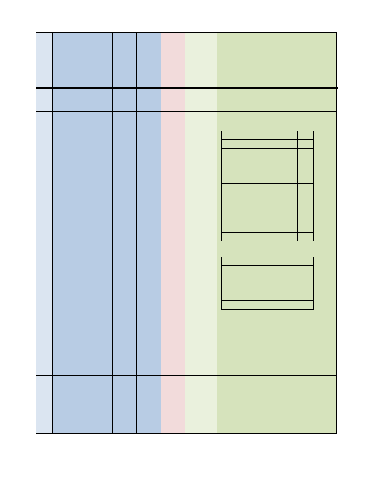
Firing mode options
Zero Cross
1
Single Cycle
2
Burs Firing
3
Phase Angle
4
Phase Angle + Soft Start
20
Half Cycle
10
Burst Cycle + Soft Start
19
Burst Firing + Delay Trigger
35
Burst Firing + Delay Trigger
+ Safety Ramp Peak
227
Burst Firing + Delay Trigger
+Saftyramp
99
Half Cycle + Soft Start
74
19 0 1023
0
1023
Sw X 0
x
x
Feedback Modes.
VOLTAGE
32
VOLTAGE2
0
CURRENT
64
CURRENT2
2
POWER
128
NO_FEEDBACK
1
20 0 255 0 255
- X 0
X Number of cycles to fire in burst fire mode
21 0 255 0 255
- X 0
X
No
Number of half cycles with a delay in burst
fire mode
22 0 90 0 90
° X 0
X
No
Degrees of delay from zero cross when the
first cycle is triggered to on when in Delay
Trigger Mode. (delay
for a transformer is 45 degrees)
23 0 255 0 255
x50ms
X 0 X
No
Number of 50 msec periods over which soft
start is active.
24 0 255 0 255
x50ms
X 0 X
No
Number of 50 msec periods that make up
the fixed time base (Cycle time) calculation.
25 0 1024
0
1024
HC X 0
X
X
How many half cycles to use for soft start
26 0 255 0 255
- X 1
X
X
Proportional term for the primary feedback
loop
Page 14

CD Automation Communication Manual Revo C
14
Par
Min
Max
Min UM
Max UM
UM
Write
Enable
Access
Level
1PH
2/3 PH
Description
27 0 255 0 255
- X 1
X
X
Integral term for the primary Feedback loop
28 0 255 0 255
x50ms
X 1 X
X
Number of 50 msec periods after the heater
break is detected before the alarm is
triggered
29 0 100 0 100
% X 1
X
X
Threshold of resistance that activates the HB
alarm as a percentage of the nominal load
resistance
30 0 3 0 3
Sw X 1
X
X
Baud rate for primary (RS485) Modbus port
31 0 255 0 255
Addr
X 1 X
X
Address for primary (RS485) Modbus port
32 0 5 0 5
Sw X 1
X
No:
4,7
Defines the result of closing Digital input 1
33 0 5 0 5
Sw X 1
X
No:
4,7
Defines the result of closing Digital input 2
34 0 65535
0
65535
Sw X 1
X
Defines the result of closing the output relay
35 0 1023
0
1023
Sw X 1
x
X
Used to calibrate AN1 and AN2 in Fast Tune
mode (uses current input as low/high value
and communicates if calibration was
successful
36 0 65535
0
65535
Sw -
x
X
Unit type (1PH,2PH,3PH)
37 0 1023
0
1023
V X 0
x
X
Nominal load voltage. Used to set the
% input to output voltage scaling.
38 0 9999
0
999,9
A X 0
X
X
Nominal load Current. Used to set the
% input to output current scaling.
39 0 9999
0
999,9
A -
X
X
Current transformer amperage rating
40 0 1 0 1
- -
X
X
Used for current retransmission gain
41 0 1023
0
1023
V -
X
X
Unit rating (max voltage rating for the
product ex: 480,600,690)
42 0 1023
0
1023
V -
X
X
Used to calibrate the aux voltage
43 0 1023
0
1023
V 0
X
X
Calculated aux voltage
(used to show overload/underload voltage)
44 0 3 0 3
Sw X 1
X
Process signal type for analog input 1
45 0 255 0 255
Sw X 1
X
X
Baud rate, secondary Modbus port
(if mounted)
46 0 65535
0
655,35
ohm 0
X
X
Calculated resistance of the load. Based on
a calculation of the Vrms load voltage
divided by the Irms load current. (Average
Irms in multi-phase unit)
47 0 65535
0
65535
V 0
X
X
AUX RMS input voltage
48 0 65535
0
65535
- 0
X
X
Version number (X.XX.X)
49 0 65535
0
65535
- 0
X
X
Year and week of release (YYWW)
Page 15

CD Automation Communication Manual Revo C
15
Par
Min
Max
Min UM
Max UM
UM
Write
Enable
Access
Level
1PH
2/3 PH
Description
50 - 0 X
X
Not used
51 0 X
X
Not used
52 0 1 0 1
X 0
X
No
Selector for the current limit
53 0 65535
0
65535
ohm 0
X
X
Used for calibrating the calculation of
resistance (not used)
54 0 4096
0
4096
A 0
X
X
Measured RMS Current - phase 1
55 0 4096
0
4096
A 0
No
X
Measured RMS Current - phase 2
56 0 4096
0
4096
A 0
No
X
Measured RMS Current - phase 3
57 0 1023
0
1023
- 0
X
X
Measured RMS Voltage (scaled 0-1023)
58 0 1023
0
1023
- 0
X
X
Measured RMS Current (scaled 0-1023)
59 0 1023
0
1023
- 0
X
X
Measured RMS Power (scaled 0-1023)
60 0 1023
0
1023
Sw X 1
X
X
Output value displayed when the Aspyre
starts up
61 0 65535
0
65535
- X 1
X
X
Selects which analog input is used for the SP
input
62 0 9999
0
9999
A -
X
X
Aspyre Amperage Rating
63 0 255 0 255
- X 1
X
No
Proportional term for the current limit loop
64 0 255 0 255
- X 1
X
No
Integral term for the current limit loop
65 0 65535
x50mS
X 0 X
No
Once the output turns off, how much time
must pass before safety ramp will be reenabled
66 0 65535
x50mS
X 0 X
No
Time for the safety rmap
67 1 9999
0
99,99
-
X
X
Current transformer gain correction
68 0 1024
0
1024
X 1
X
X
Selects the parameter to retransmit
69 0 1024
0
1024
X 1
X
X
Selects the electrical type of the retransmit
70 0 255 0 255
s X 1
X
X
Data logging period
71 0 255 0 255
X 2
X
X
IP Address for Hilscher module
72 0 255 0 255
X 2
X
X
73 0 255 0 255
X 2
X
X
74 0 255 0 255
X 2
X
X
75 0 255 0 255
X 2
X
X
Mask for the Hilscher module
76 0 255 0 255
X 2
X
X
77 0 255 0 255
X 2
X
X
Page 16

CD Automation Communication Manual Revo C
16
Par
Min
Max
Min UM
Max UM
UM
Write
Enable
Access
Level
1PH
2/3 PH
Description
78 0 255 0 255
X 2
X
X
79 0 255 0 255
X 2
X
X
Gateway for the Hilscher module
80 0 255 0 255
X 2
X
X
81 0 255 0 255
X 2
X
X
82 0 255 0 255
X 2
X
X
83 0 65535
0
65535
X 1
X
X
WiFi Machine Name
(2 characters each, 16 characters total)
PROFINET NAME: 120 WORDS IN EXTERNAL
ADDRESS MAP(from address 300 to 420)
84 0 65535
0
65535
X 1
X
X
85 0 65535
0
65535
X 1
X
X
86 0 65535
0
65535
X 1
X
X
87 0 65535
0
65535
X 1
X
X
88 0 65535
0
65535
X 1
X
X
89 0 65535
0
65535
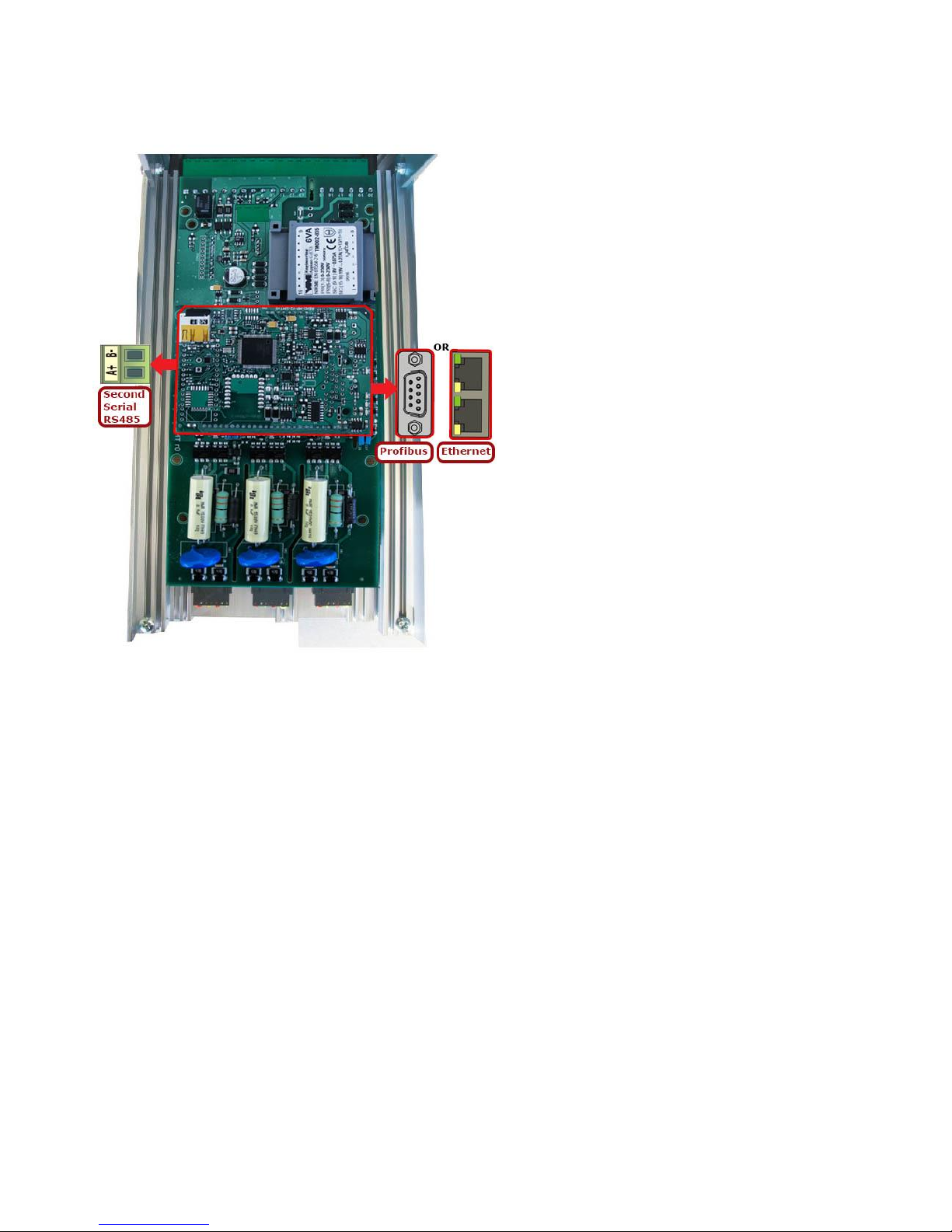
X 1
X
X
90 0 65535
0
65535
X 1
X
X
91 0 65535
0
65535
X 0 X
X
DAY_MONTH
8 bit H-> DAY 8 bit L ->MONTH
92 0 65535
0
65535
X 0 X
X
YEAR_HOUR
8 bit H-> YEAR 8 bit L ->HOUR
93 0 65535
0
65535
X 0 X
X
MIN_SEC
8 bit H-> MIN 8 bit L ->SEC
94 0 255
0
X
X
IP Address for WiFi module
95 0 255
0
X
X
96 0 255
0
X
X
97 0 255
0
x
X
98 0 9995
0
9995
ms X 2
No
X
Delay for zero cross of phase 1
99 0 9995
0
9995
ms X 2
No
X
Delay for zero cross of phase 2
100 0 9995
0
9995
ms X 2
No
X
Delay for zero cross of phase 3
101 0 1 0 1
Sw X 1
X
No
Enable the current limit (0 - off / 1 - on)
102 0 1000
0
1000
ratio
0 X
X
Power Factor
103 0 1000
0
1000
ratio
0
No
X
(not used)
104 0 1000
0
1000
ratio
0
No
X
(not used)
105 0 3 0 3
X 1
x
X
Process signal type for analog input 2
106 0 4096
0
4096
-
X
X
stored calibration value
Page 17

CD Automation Communication Manual Revo C
17
Par
Min
Max
Min UM
Max UM
UM
Write
Enable
Access
Level
1PH
2/3 PH
Description
107 0 4096
0
4096
-
X
X
(internal use)
108 0 4096
0
4096
-
X
X
109 0 4096
0
4096
-
X
X
110 0 4096
0
4096
-
X
X
111 0 4096
0
4096
-
X
X
112 0 4096
0
4096
-
X
X
113 0 4096
0
4096
-
X
X
114 0 4096
0
4096
-
X
X
115 0 4096
0
4096
-
X
X
116 0 2 0 2
Sw X 1
X
No
Function associated with AN2
117 0 9999
0
9999
-
X
X
Gain for power set point
(general gain gets copied into here if you
select to retransmit set point)
118 0 9999
0
9999
-
X
X
Gain for measured power rtx (VxI)
(general gain gets copied into here if you
select to retransmit power)
119 0 2
Sw -
X
X
Select which Hilscher module you have
populated
120 0 1
Sw 2
X
X
Enable the WiFi (0 - off / 1 - on)
121 0 65535
0
X
X
Internal use (used by Thyristor Configurator
to know which family is connected)
(0x07)
122 0 1024
X 1
X
X
If PROFIBUS is mounted, this is the external
address that is used to communicate over
PROFIBUS
123 0 65535
kVA X 0
X
X
Real Time power consumption calculation
(read only, can set to 0 to reset total count)
124 0 65535
X 1
X
X
General retransmission gain (automatically
copied into the correct position based on
the retransmission parameter that you
selected
125 0 65535
kW/h
0 X
X
Total count in kW/h
126 0 65535
0
X
X
127 0 1200 0 120
°C 0 X X
Temperature of the SCR (if NTC, you will see
the value, if T Stat 0 - okay / 1- alarm)
128 0 1200 0 120
°C X 3
x
X
Alarm set point for SCR (setting to 0 disables
this alarm)
129 0 4096
0
4096
-
X
X
Calibration value for AI1
Page 18

CD Automation Communication Manual Revo C
18
Par
Min
Max
Min UM
Max UM
UM
Write
Enable
Access
Level
1PH
2/3 PH
Description
130 0 4096
0
4096
-
X
X
131 0 65535
kW 0
X
X
Real time power consumption calculation
(includes power factor, internal use)
132 0 65535
-
X
X
Voltage value in calibration (used for scaling)
133 0 65535
-
X
X
Frequency value in calibration (used for
scaling)
134 0 9999
0
9999
-
X
X
Gain for voltage rtx (general gain gets copied
into here if you select to retransmit set
point)
135 0 9999
0
9999
-
X
X
Gain for current rtx (general gain gets copied
into here if you select to retransmit set
point)
136
0 X
X
Not used
137 0 1000
0
100,0
0
X
X
Current value of analog input 2 in percent
138 0 1000
0
100,0
0
X
X
Current value of analog input 1 in percent
139 0 1
X 0
X
X
Start or stop data logging (0 - off / 1 - on)
140 0 1
0
X
No
Enable bakeout function (0 - off / 1 - on)
141 0 65535
-
X
X
Used to select CDA protocol for Data log file
transfer, Live mode
(bit0 - Live Mode / bit1 - file upload mode)
142 0 1
X 1
X
X
Enable to Modbus watchdog
143 0 255
s X 1 X
Amount of time to wait before trigging
watchdog if no message is received before
triggering alarm
144 0 9999
min X 1
X
No
Bakeout total ramp time in minutes
145 0 9999
A X 1
X
No
Bakeout current limit
146 0 9999
min X 1
X
No
Time to wait while off before bakeout is
needed again (time for the heater to cool)
147 0 1024
0
X
X
Scaled AN1 value (0-1024)
148 0 1024
0
X
X
Scaled AN2 value (0-1024)
149 0 9999
-
X
X
Serial Number
150 0 9999
-
X
X
151 0 9999
-
X
X
152 0 9999
-
X
X
153
0
1000
0 X
X
154
0 Not used
Page 19
CD Automation Communication Manual Revo C
19
Par
Min
Max
Min UM
Max UM
UM
Write
Enable
Access
Level
1PH
2/3 PH
Description
155
0 Not used
156
0 Not used
157
0 Not used
158 0 65535
0 X X
CRC used for WiFi communication
159 0 65535
0
X
X
16 bit CRC of Modbus map
Page 20
CD Automation Communication Manual Revo C
20
2 Fieldbus
The Revo C is available in these fieldbus types:
• MODBUS/TCP
• PROFINET
• PROFIBUS DP
NOTE: In order change the write parameters (see page 42) from Configuration Software (USB
port) or from RS485 Modbus-RTU port, write from fieldbus must be disabled. If the connection is
terminated/compromised, these parameters will be continuously set to 0 until parameter 2 is
disabled or the connection is re-established and the parameters are set.
To disable write from bus use parameter 2
Parameter 2:
Par
Min
Max
Min UM
Max UM
UM
Write
En
Access
Level
1PH
2/3 PH
Description
2 0 1 1 X
X
Used to temporarily disable Field
Communications
0:Enabled
1: Disabled
Page 21
CD Automation Communication Manual Revo C
21
2.1 MODBUS/TCP
2.1.1 General description
The thyristor unit permit a data exchange via Modbus/TCP to an external device (HMI or PLC).
2.1.2 PROFINET Connection
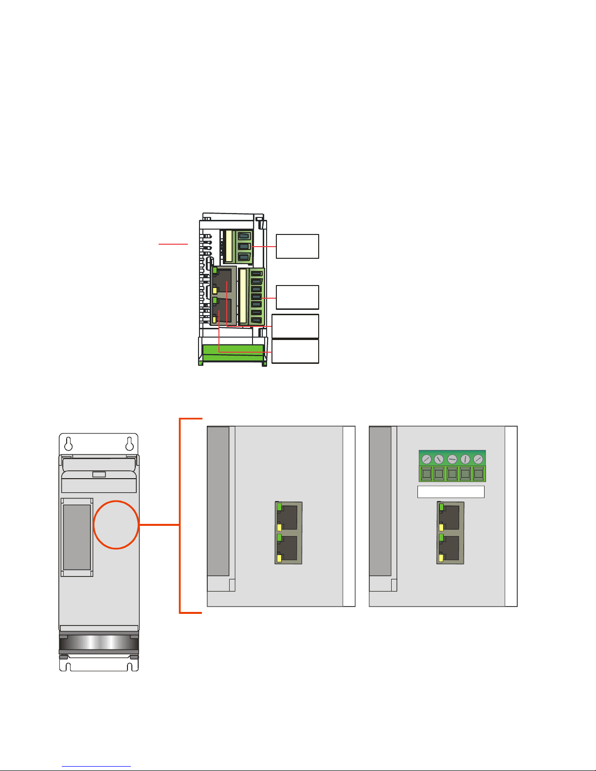
2.1.2.1 Communication Terminals 30-40A (SR9-SR10-SR11)
Ethernet Configuration Connectors
M1
M4
Eth2
Eth1
M1
M4
10 11 12 13 14 15 16
L1 L2 N
\
Leds
2.1.2.2 Communication Terminals 60-210A(From SR12 to SR17)
1 2 3 4 5
24V
GND
The LED status is internal.
If available
Page 22
CD Automation Communication Manual Revo C
22
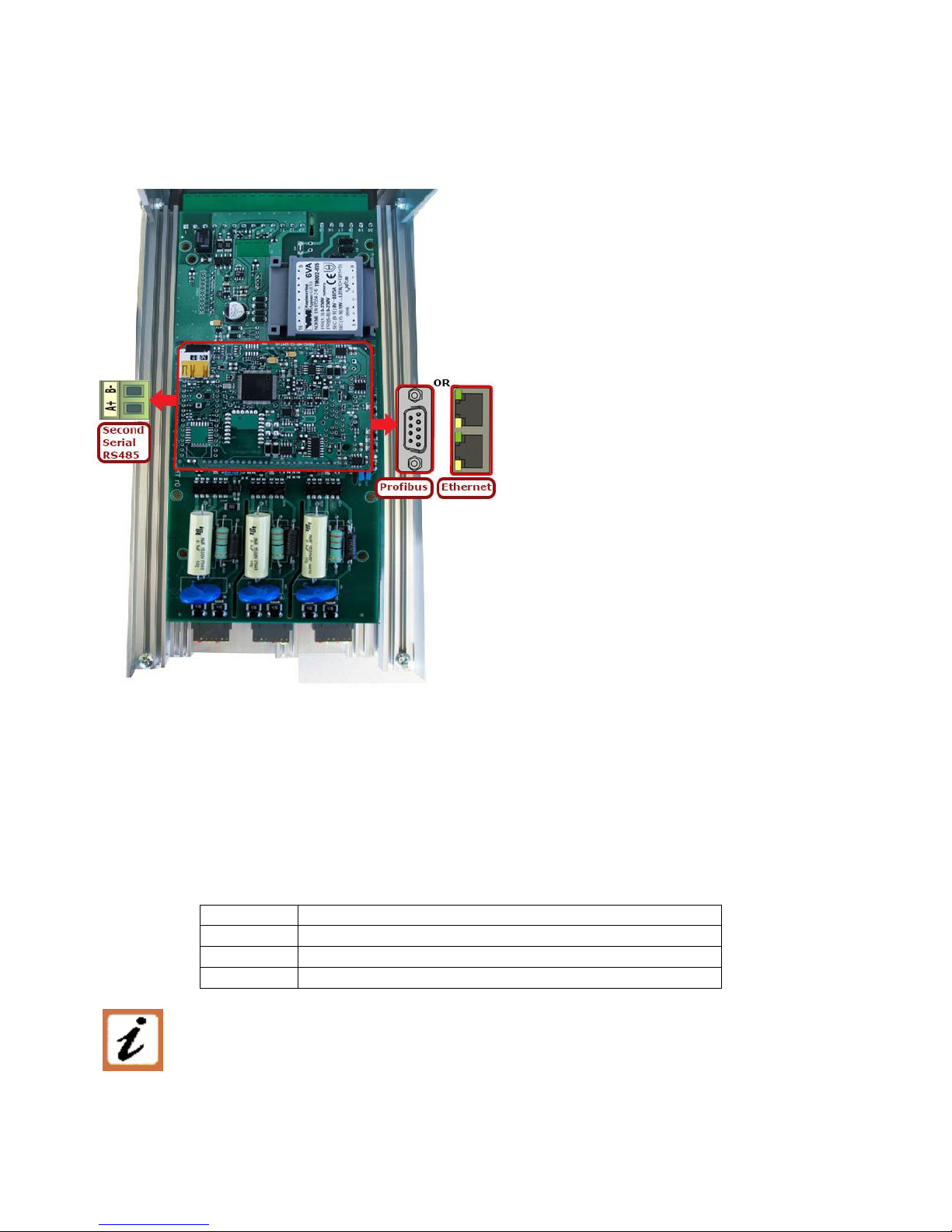
2.1.2.3 Communication Terminals 300-700A (S12-S13-S14)
2.1.3 MODBUS/TCP Protocol
The communication is based on the standard industrial MODBUS TCP with the following
restrictions:
The following MODBUS functions are supported:
Function
Description
04
Read Input Registers
06
Preset Single Registers
16
Preset Multiple Registers
The unit support the Broadcast messages:
It' possible send a Broadcast messages using the address 0, all the units respond at
the message without sending back any reply.
2.1.4 PLC/Device Configuration
The device to connect to the unit need to set the correct IP address, the port and the unit ID
Default values are:
Page 23
CD Automation Communication Manual Revo C
23
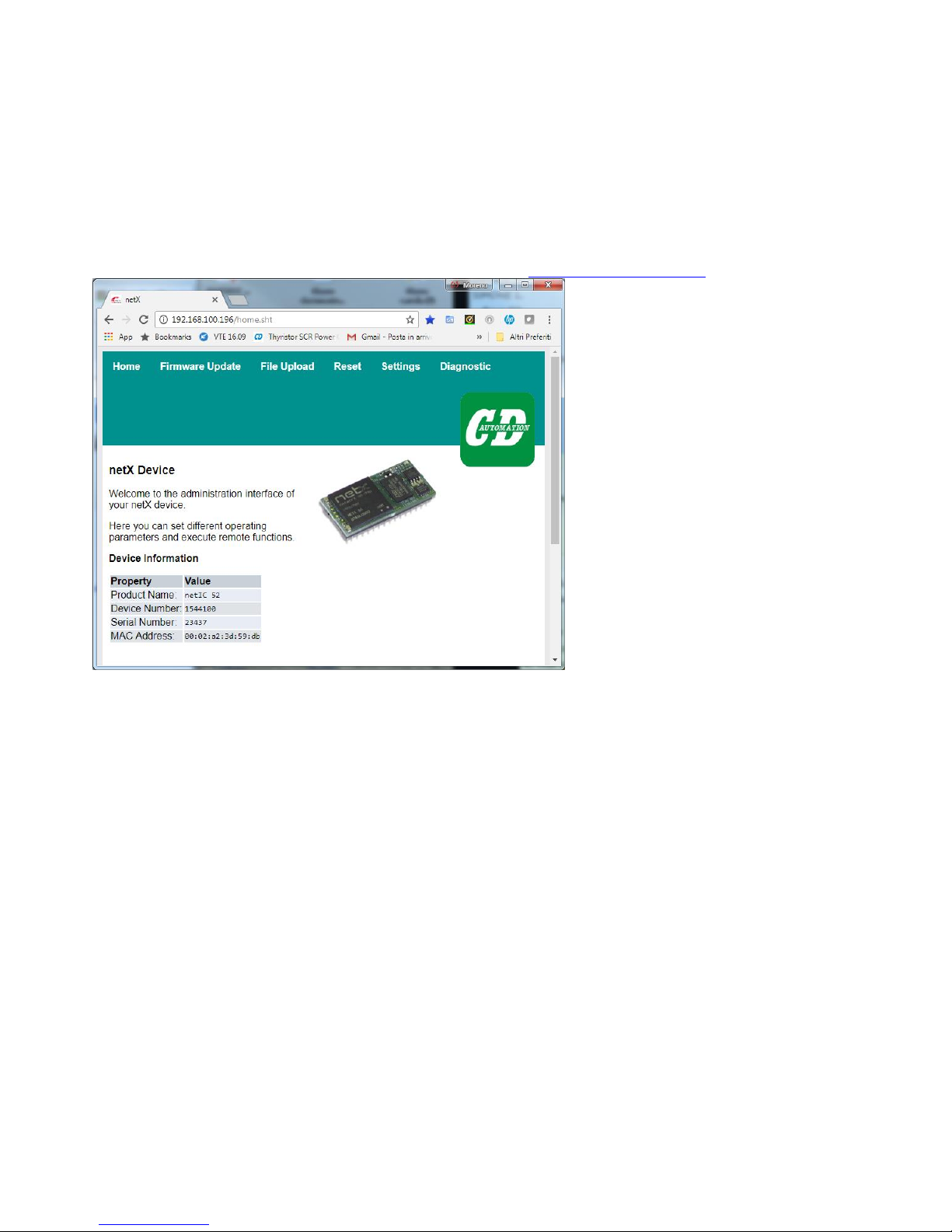
IP: 192168.100.196
S.M.: 255.255.255.0
Gateway: 192.168.100.101
2.1.5 Instrument IP Setting
On Software configuration is not possible set IP address, but only see the value.
Is possible to set it via web page or via application software
2.1.5.1 set IP Andress via web page
Open a browser and set on URL the actual IP address (Ex: http://192.168.100.196 )
Click on settings and when credentials are required, set:
User : ute1
Password : ute1_
Page 24
CD Automation Communication Manual Revo C
24
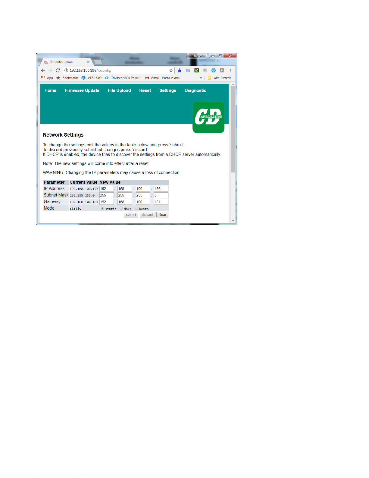
Will appear a page with IP address, Subnet Mask, Gateway and Mode,
set the configuration required and click on “submit” button to confirm
Page 25
CD Automation Communication Manual Revo C
25
2.1.5.2 set IP address desktop application
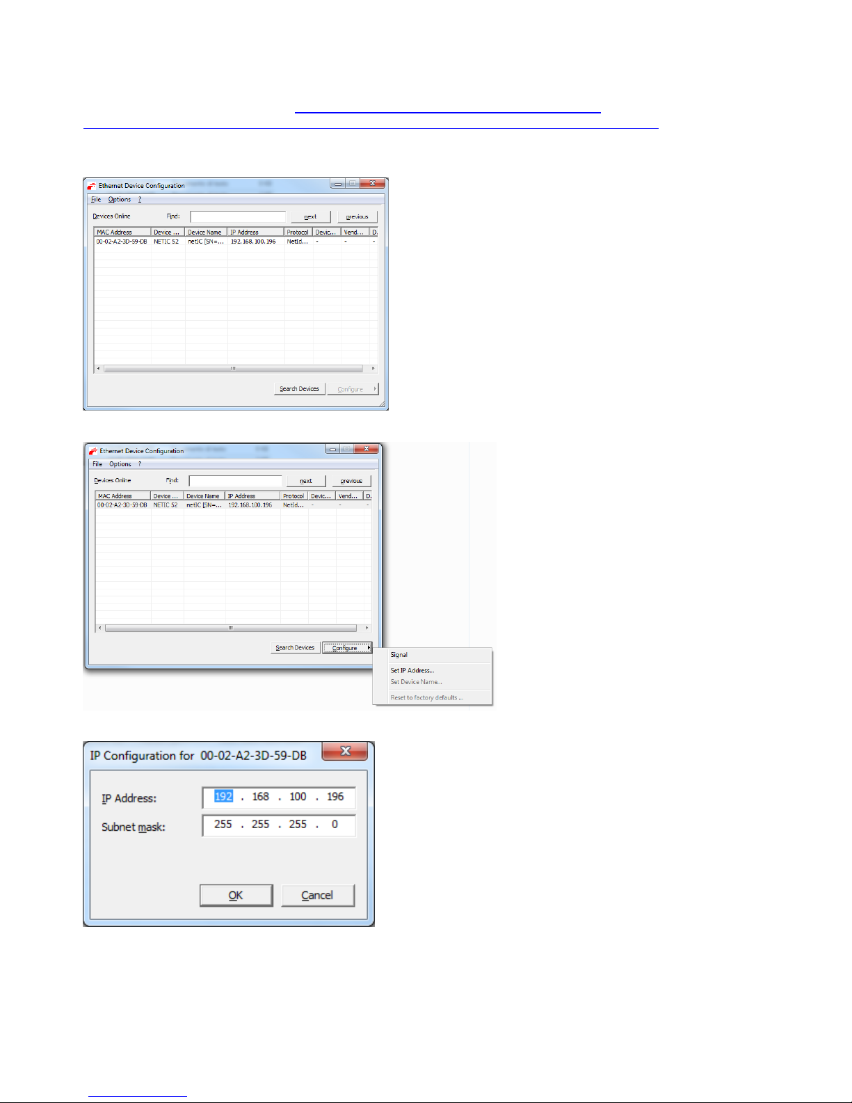
With a search tool on Ethernet (https://www.cdautomation.com/download/cd-
automation/software/fieldbus/EthernetDeviceConfiguration_V1.0900.1.8378-Setup.msi )
Is possible to search the units connected to the network, read the MAC address and set the correct
IP address
To set the IP address select the device with mouse left button and click on “Configure” button
Click on “Set IP address”
Write the right IP and Snubnet Mask and click OK to confirm
Page 26
CD Automation Communication Manual Revo C
26
2.2 PROFINET
2.2.1 General description
The thyristor unit permit a data exchange via PROFINET-IO Siemens protocol.
2.2.2 PROFINET Connection
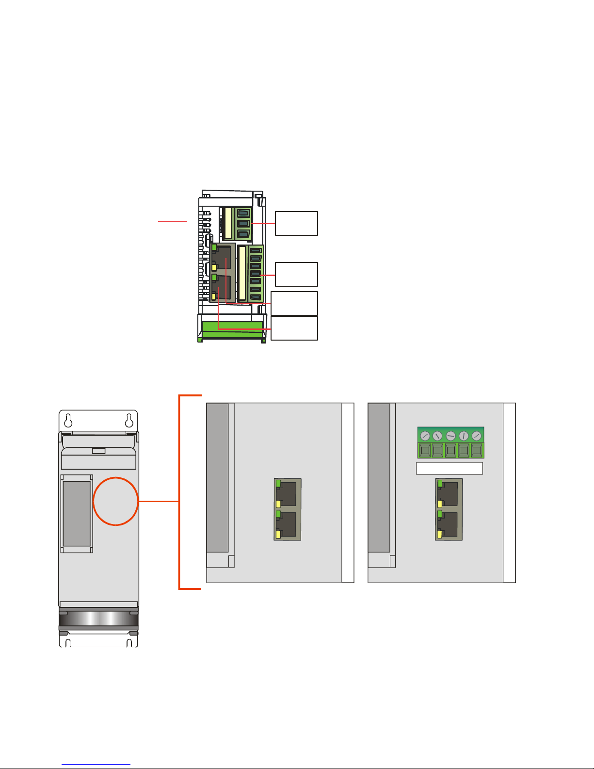
2.2.2.1 Communication Terminals 30-40A (SR9-SR10-SR11)
Ethernet Configuration Connectors
M1
M4
Eth2
Eth1
M1
M4
10 11 12 13 14 15 16
L1 L2 N
\
Leds
2.2.2.2 Communication Terminals 60-210A(From SR12 to SR17)
1 2 3 4 5
24V
GND
The LED status is internal
Page 27
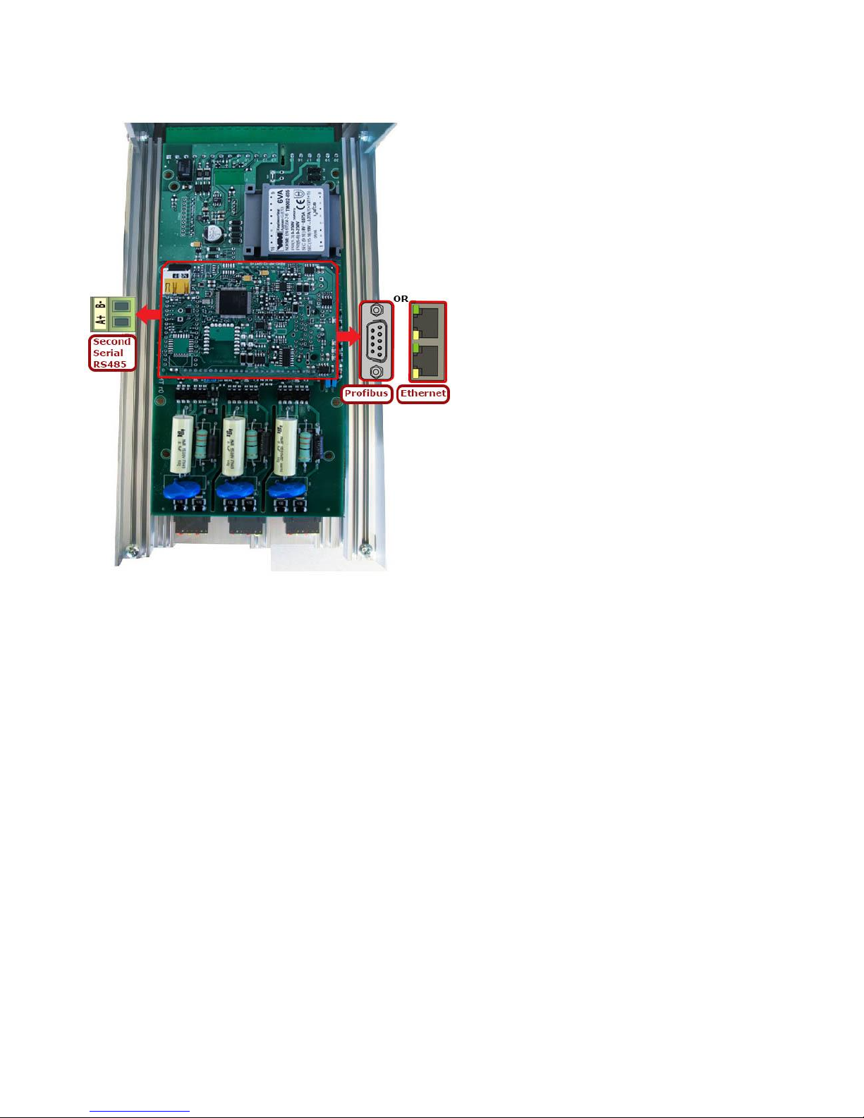
CD Automation Communication Manual Revo C
27
2.2.2.3 Communication Terminals 300-700A (S12-S13-S14)
Page 28
CD Automation Communication Manual Revo C
28
2.2.3 PLC Configuration
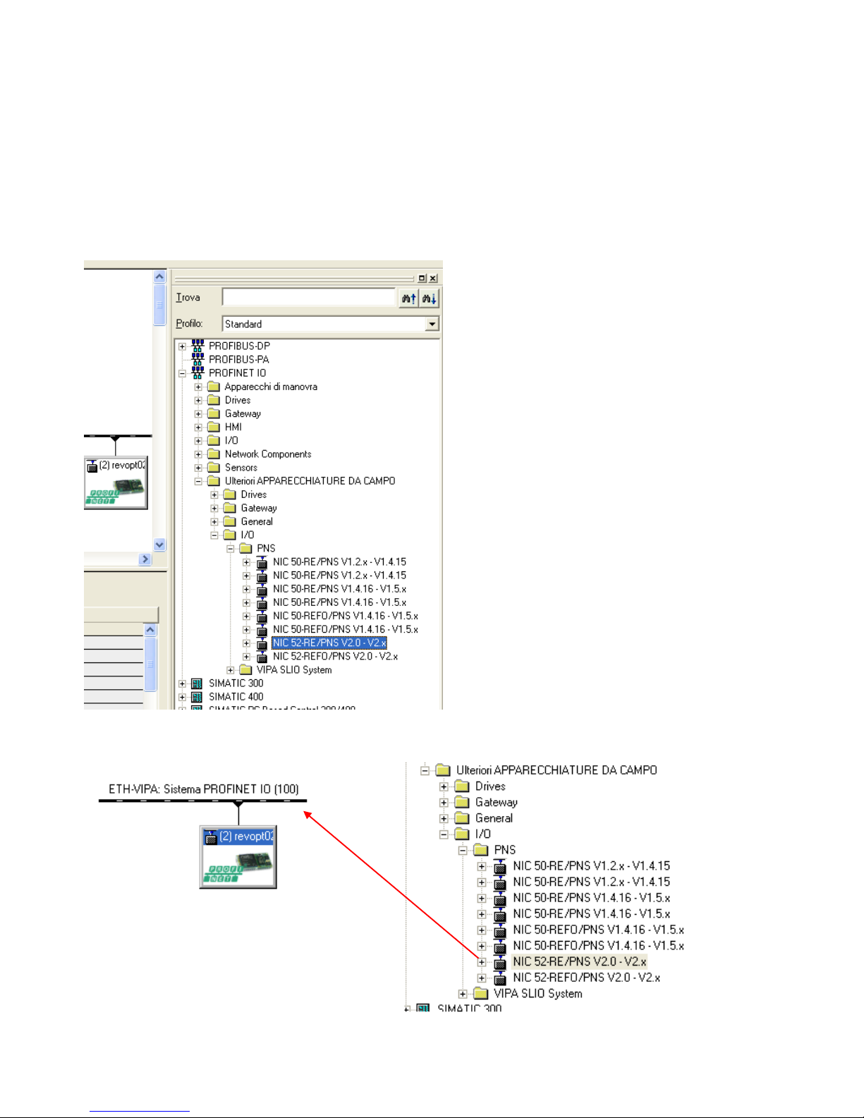
With PROFINET connection is possible read value in cyclic mode.
To do it you need use de GSDML plc configuration file that describe the product, and install in PLC
configuration software environment.
(GSDML-V2.32-HILSCHER-NIC 5X-RE PNS-20161102.xml)
If GSDML file is not installed, please install it
If installed or after installation will be present (NIC 52-RE/PNS V2.0-V2.x)
So is possible drag and drop it on network
Page 29
CD Automation Communication Manual Revo C
29
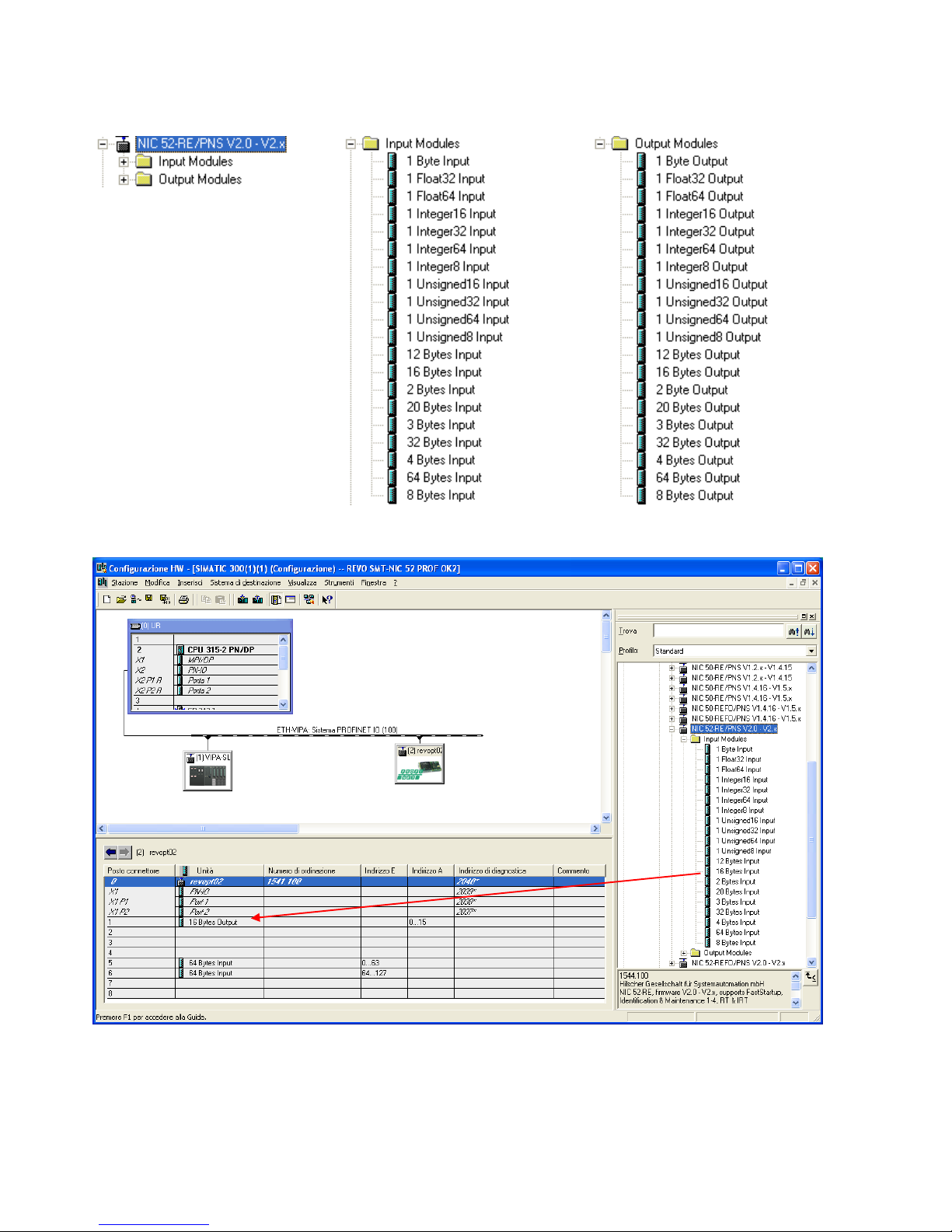
After expand Input and output
And set Input and output with drag and drop
Page 30
CD Automation Communication Manual Revo C
30
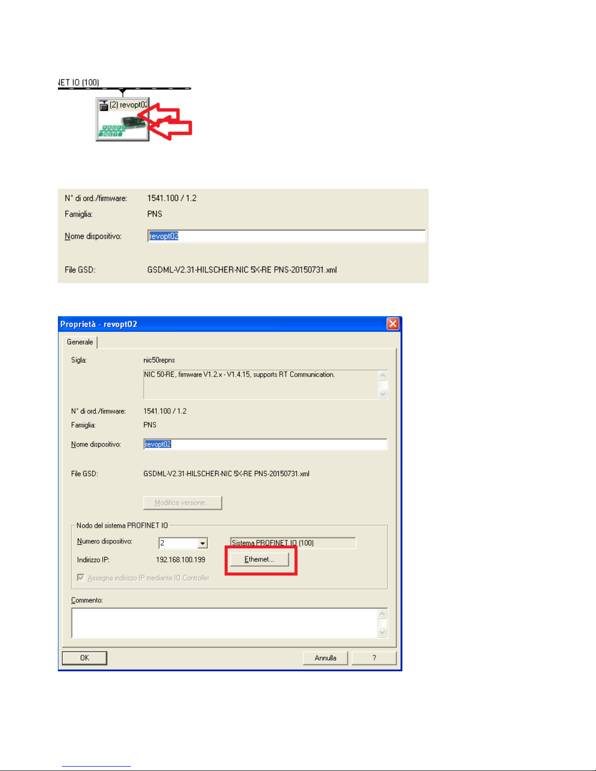
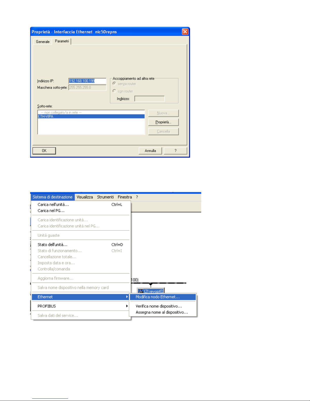
Set the configuration IP address and Name with double-click on it
Fill the Device Name
Click on Ethernet
Set the IP address
Page 31
CD Automation Communication Manual Revo C
31
Now save and send configuration to the PLC
Now we will set the Name to the THYRISTOR unit with Siemens tools
Page 32
CD Automation Communication Manual Revo C
32
2.3 PROFIBUS
2.3.1 General description
The thyristor unit permit a data exchange via PROFIBUS-DP Siemens protocol.
2.3.2 PROFIBUS Connection
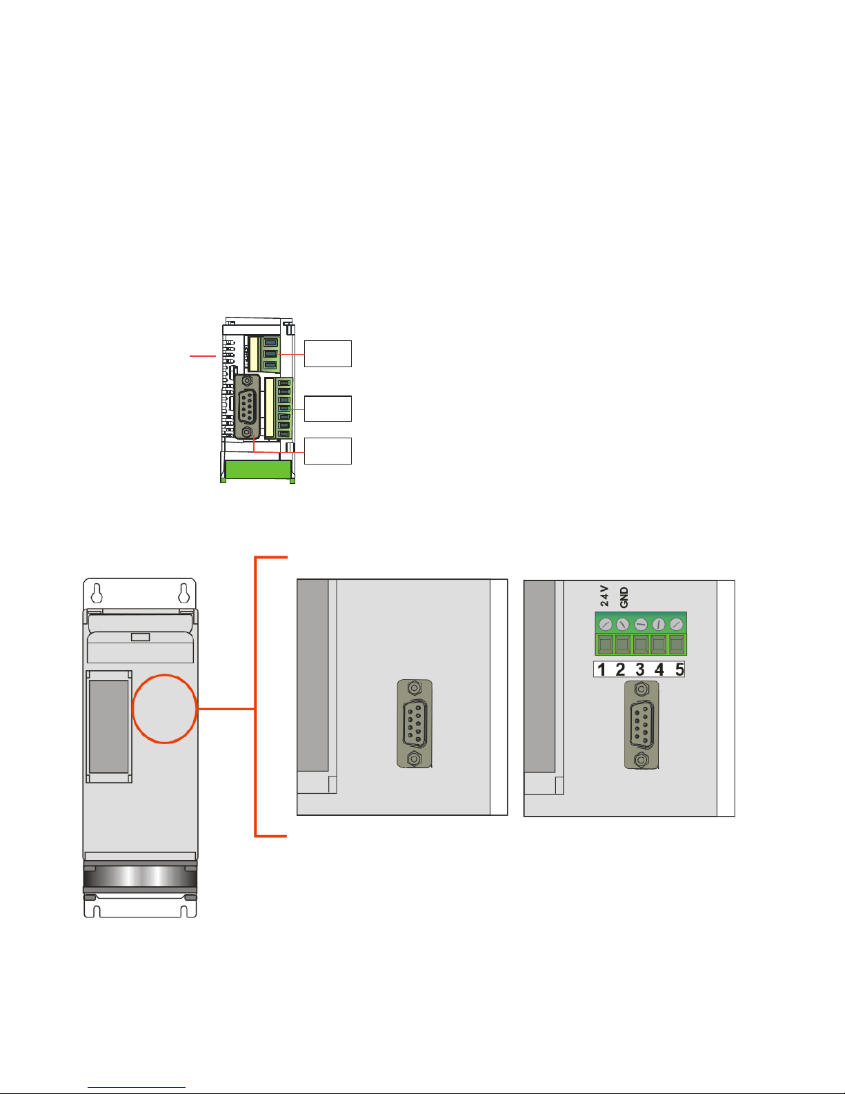
2.3.2.1 Communication Terminals 30-40A (SR9-SR10-SR11)
Ethernet Configuration Connectors
M1
M4
Pr1
M1
M4
10 11 12 13 14 15 16
L1 L2 N
\
Leds
2.3.2.2 Communication Terminals 60-210A(From SR12 to SR17)
The LED status is internal
Page 33
CD Automation Communication Manual Revo C
33
2.3.2.3 Communication Terminals 300-700A (S12-S13-S14)
Page 34
CD Automation Communication Manual Revo C
34
2.3.3 PLC Configuration
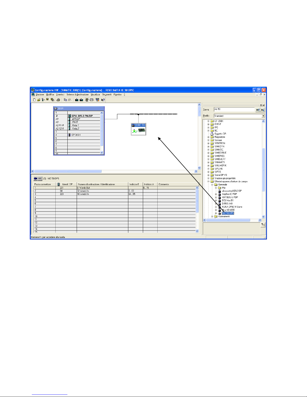
With PROFIBUS connection is possible read value in cyclic mode.
To do it you need use de GSD plc configuration file that describe the product, and install in PLC
configuration software environment.
If GSD file is not installed, please install it
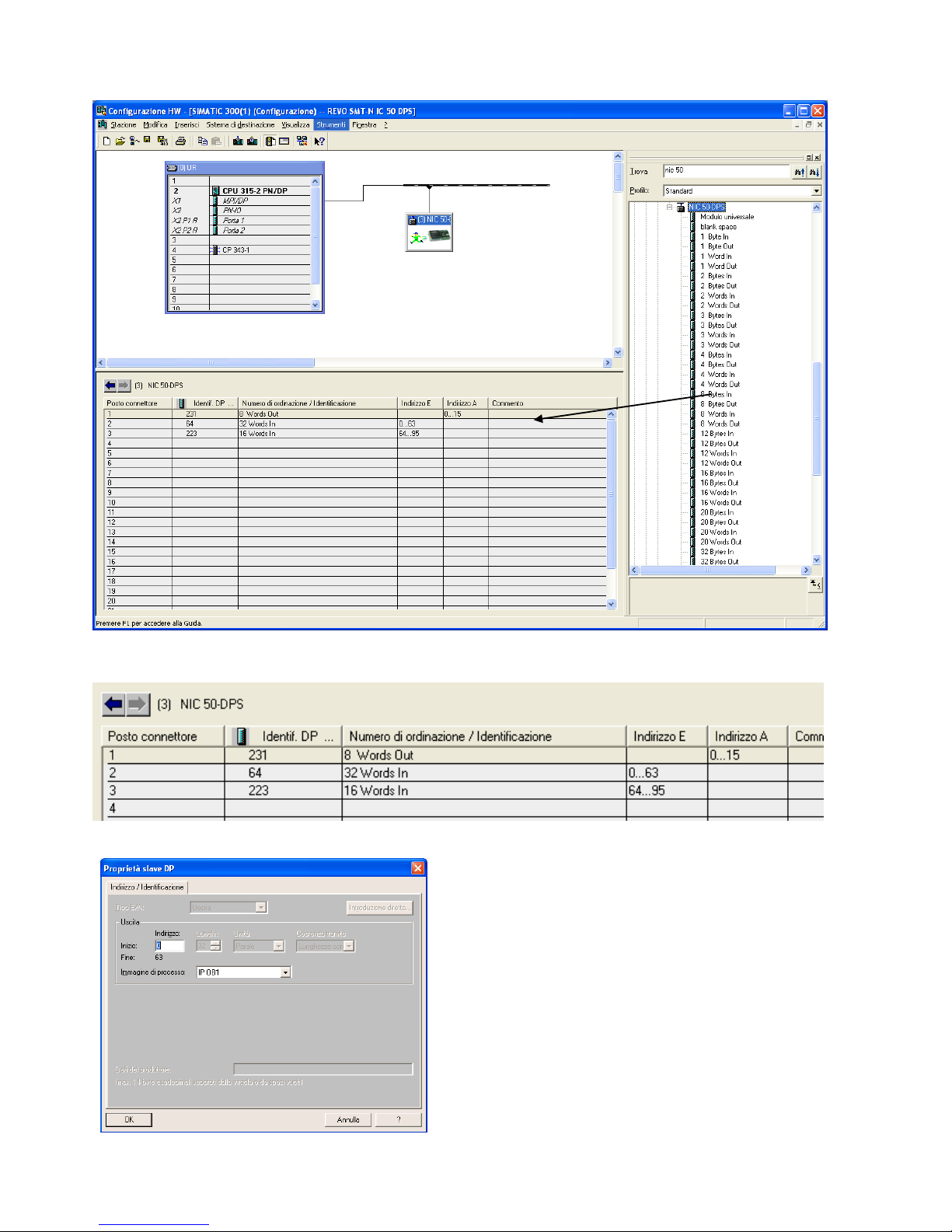
If installed or after installation will be present (NIC 50-DPS)
Page 35
CD Automation Communication Manual Revo C
35
And set Input and output with drag and drop
NOTE:
The module must have the right sequence
Is important the position, and the:
• Position 1 must be 8 Word OUT
• Position 2 must be 32 Word IN
• Position 2 must be 16 Word IN
After is possible assign the start address with a
double click on it
Page 36

CD Automation Communication Manual Revo C
36
2.4 Data Exchange Area
2.4.1 Read area
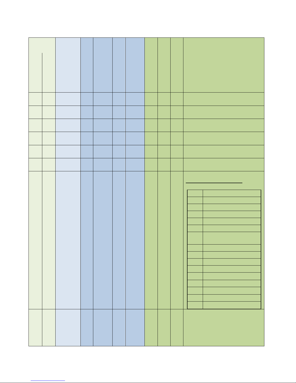
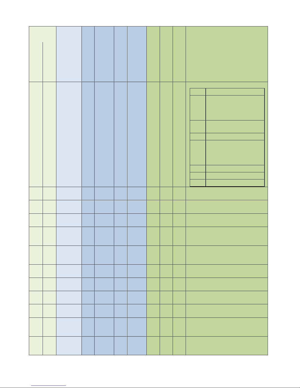
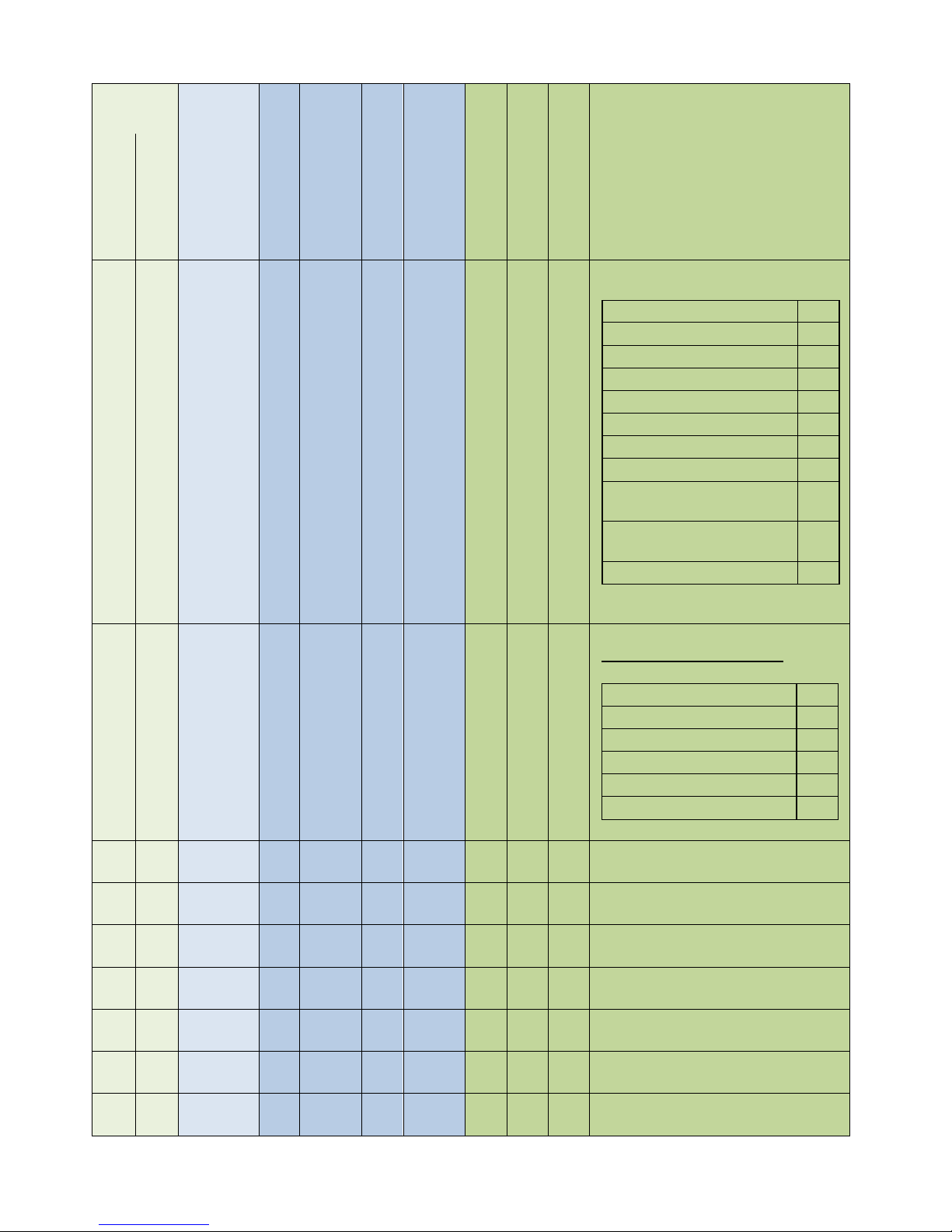
Columns
Byte Bus Offset:
The number of bytes from the “0” address to the parameter start
address
Word Bus Offset:
The number of “Words” offset from the “0” address.
Parameter
Number:
The Modbus parameter number
(Is Input register, so to read the data you Must use function 4)
Min:
the minimum actual value of the parameter.
Max:
the maximum actual value of the parameter.
Min UM:
The minimum value translated to its unit of measurment
Max UM:
The maximum value translated to its unit of measurment
UM:
Unit of measurment
1PH:
Checked if available on a single phase unit
2/3PH:
Checked if available on a two/three phase unit
Page 37
CD Automation Communication Manual Revo C
37
PROFIBUS
PROFINET
MODBUS
TCP
Byte Buss Offset
Word Bus
Offset
Parameter
number
Func 4
Min
Max
Min UM
Max UM
UM
1PH
2/3 PH
Description
0
0
0
30001
Not used
2
1
1
30002
Not used
4
2
2
30003
0
65535
0
655,35
Hz X X
Main network frequency
6
3
3
30004
0
1023
0
1023
V X X
Rms Voltage or average Voltage of
rms for multi-phase
8
4
4
30005
0
1023
0,0
102,3
A X X
RMS Current or Average RMS
Current (multi-phase)
10
5
5
30006
0
1023
0
1023
% X X
RMS Power or Average RMS Power
(multi-phase)
12
6
6
30007
0
1023
0
1023
Sw x x
Status bitmask
See relative Tables Chapter.
bit0
ShortCut Alarm
bit1
Heat Break Alam
bit2
ON/OFF unit
bit3
Not used
bit4
Current Limit Alarm
bit5
Therma Alarm
bit6
Communication Alarm
( WD)
bit7
Not used
bit8
Digital input 1 status
bit9
Digital input 2 status
bit10
Not used
bit11
Not used
bit12
Not used
bit13
Not used
bit14
Not used
bit15
Thermal Alarm active
Page 38
CD Automation Communication Manual Revo C
38
PROFIBUS
PROFINET
MODBUS
TCP
Byte Buss Offset
Word Bus
Offset
Parameter
number
Func 4
Min
Max
Min UM
Max UM
UM
1PH
2/3 PH
Description
14
7
7
30008
0
255
0
1023
Sw X 0
Command bitmask
bit0
Not used
bit1
Digital Reference
0= from analogue input
1= from
communication/keyb.
bit2
Unit enable
1= Enable 0= Disable
bit3
Not used
bit4
Current Limit Switch
0= from analogue input
1= from
communication/keyb.
bit5
Not used
bit6
Save Factory
bit7
Load Factory
16
8
8
30009
0
1023
0,0
100,0
% X X
Remote setpoint for unit
18
9
9
30010
0
255 0 100
% X X
How to scale the power set point
20
10
10
30011
0
1023 0 100
% X No
Digital current limit value
(local/remote)
22
11
11
30012
0
1023
0
1023
V x X
Nominal load voltage. Used to set
the % input to output voltage
scaling.
24
12
12
30013
0
9999
0
999,9
A X X
Nominal load Current. Used to set
the % input to output current
scaling.
26
13
13
30014
0
4096
0
4096
A X X
Measured RMS Current - phase 1
28
14
14
30015
0
4096
0
4096
A
No
X
Measured RMS Current - phase 2
30
15
15
30016
0
4096
0
4096
A
No
X
Measured RMS Current - phase 3
32
16
16
30017
0
65535
0
65535
V X X
AUX RMS input voltage
34
17
17
30018
0
65535
kW X X
Real time power consumption
calculation (includes power factor,
internal use)
36
18
18
30019
0
65535
kV
A
X
X
Real Time power consumption
calculation (read only, can set to 0 to
reset total count)
Page 39

CD Automation Communication Manual Revo C
39
PROFIBUS
PROFINET
MODBUS
TCP
Byte Buss Offset
Word Bus
Offset
Parameter
number
Func 4
Min
Max
Min UM
Max UM
UM
1PH
2/3 PH
Description
38
19
19
30020
0
65535
kW
/h
X
X
Total count in kW/h
40
20
20
30021
0
65535
X X
42
21
21
30022
0
1000
0
1000
rati
o
X
X
Power Factor
44
22
22
30023
0
1000
0
1000
rati
o
No
X
(not used)
46
23
23
30024
0
1000
0
1000
rati
o
No
X
(not used)
48
24
24
30025
0
1200 0 120
°C X X
Temperature of the SCR (if NTC, you
will see the value, if T Stat 0 - okay /
1- alarm)
50
25
25
30026
0
65535
0
655,35
oh
m
X
X
Calculated resistance of the load.
Based on a calculation of the Vrms
load voltage divided by the Irms load
current. (Average Irms in multi-phase
unit)
52
26
26
30027
0
65535
0
65535
oh
m
X
X
Used for calibrating the calculation
of resistance (not used)
54
27
27
30028
0
65535
0
65535
Sw x X
Unit type (1PH,2PH,3PH)
56
28
28
30029
0
1023
0
1023
V X X
Unit rating (max voltage rating for
the product ex: 480,600,690)
58
29
29
30030
0
9999
0
9999
A X X
Aspyre Amperage Rating
60
30
30
30031
0
1023
0
1023
V X X
Calculated aux voltage
(used to show overload/underload
voltage)
Page 40
CD Automation Communication Manual Revo C
40
PROFIBUS
PROFINET
MODBUS
TCP
Byte Buss Offset
Word Bus
Offset
Parameter
number
Func 4
Min
Max
Min UM
Max UM
UM
1PH
2/3 PH
Description
62
31
31
30032
0
1023
0
1023
Sw
X
Only
ZC
BF
Firing mode options
Zero Cross
1
Single Cycle
2
Burs Firing
3
Phase Angle
4
Phase Angle + Soft Start
20
Half Cycle
10
Burst Cycle + Soft Start
19
Burst Firing + Delay Trigger
35
Burst Firing + Delay Trigger
+ Safety Ramp Peak
227
Burst Firing + Delay Trigger
+Saftyramp
99
Half Cycle + Soft Start
74
64
32
32
30033
0
1023
0
1023
Sw x x
Feedback Modes.
See relative Tables Chapter.
VOLTAGE
32
VOLTAGE2
0
CURRENT
64
CURRENT2
2
POWER
128
NO_FEEDBACK
0
66
33
33
30034
0 1 0 1 X No
Selector for the current limit
68
34
34
30035
0
65535
0
65535
- X X
Selects which analog input is used
for the SP input
70
35
35
30036
0
1000
0
100,0
% X X
Current value of analog input 1 in
percent
72
36
36
30037
0
1000
0
100,0
% X X
Current value of analog input 2 in
percent
74
37
37
30038
0 5 0 5 Sw
X
No:
4,7
Defines the result of closing Digital
input 1
76
38
38
30039
0 5 0 5 Sw
X
No:
4,7
Defines the result of closing Digital
input 2
78
39
39
30040
0
65535
0
65535
Sw X
Defines the result of closing the
output relay
Page 41

CD Automation Communication Manual Revo C
41
PROFIBUS
PROFINET
MODBUS
TCP
Byte Buss Offset
Word Bus
Offset
Parameter
number
Func 4
Min
Max
Min UM
Max UM
UM
1PH
2/3 PH
Description
80
40
40
30041
0
65535
x50
mS
X
No
Once the output turns off, how much
time must pass before safety ramp
will be re-enabled
82
41
41
30042
0
65535
x50
mS
X
No
Time for the safety ramp
84
42
42
30043
0 1 X No
Enable bakeout function (0 - off / 1 on)
86
43
43
30044
0
9999
min X No
Bakeout total ramp time in minutes
88
44
44
30045
0
9999
A X No
Bakeout current limit
90
45
45
30046
0
9999
min X No
Time to wait while off before
bakeout is needed again (time for
the heater to cool)
92
46
46
30047
0 1 X X
Start or stop data logging (0 - off / 1 on)
94
47
47
30048
0 1 Sw X X
Enable the Wi-Fi (0 - off / 1 - on)
Page 42

CD Automation Communication Manual Revo C
42
2.4.2 Write area
Byte Bus Offset:
The number of bytes from the “0” address to the parameter start
address
Word Bus Offset:
The number of “Words” offset from the “0” address.
Parameter
Number:
The Modbus parameter number
(Is Holding register, so to read the data you Must use function 4
so to write the data you Must use function 6 or 16)
Min:
the minimum actual value of the parameter.
Max:
the maximum actual value of the parameter.
Min UM:
The minimum value translated to its unit of measurment
Max UM:
The maximum value translated to its unit of measurment
UM:
Unit of measurment
1PH:
Checked if available on a single phase unit
2/3PH:
Checked if available on a two/three phase unit
Page 43
CD Automation Communication Manual Revo C
43
PROFIBUS
PROFINET
Modbus
TCP
Byte Buss Offset
Word Bus
Offset
Parame
ter
number
Func 3/6/16
Min
Max
Min UM
UM
Max UM
1PH
2/3 PH
Description
0
0
0
40001
Not used
2
1
1
40002
Not used
4
2
2
40003
0
255
0
Sw
1023
X
0
Command bitmask
bit0
Not used
bit1
Digital Reference
0= from analogue input
1= from
communication/keyb.
bit2
Unit enable
1= Enable 0= Disable
bit3
Not used
bit4
Not used
bit5
Not used
bit6
Save Factory
bit7
Load Factory
bit8
Not used
bit9
Not used
bit10
Not used
bit11
Not used
bit12
Not used
bit13
Not used
bit14
Not used
bit15
Not used
.
6
3
3
40004
0
1023
0,0 % 100,0
X
X
Remote set point for unit
8
4
4
40005
0
255
0 % 100
X
X
How to scale the power set point
10 5
 Loading...