

Page 1
CD Automation S.r.l.
Via Picasso 34/36 - 20025 – Legnano (MI) – ITALY
Tel +39 0331 577479 – Fax +39 0331 579479
E-Mail: [email protected]
- WEB: www.cdautomation.com
USER’S MANUAL
Rev. 01/2007
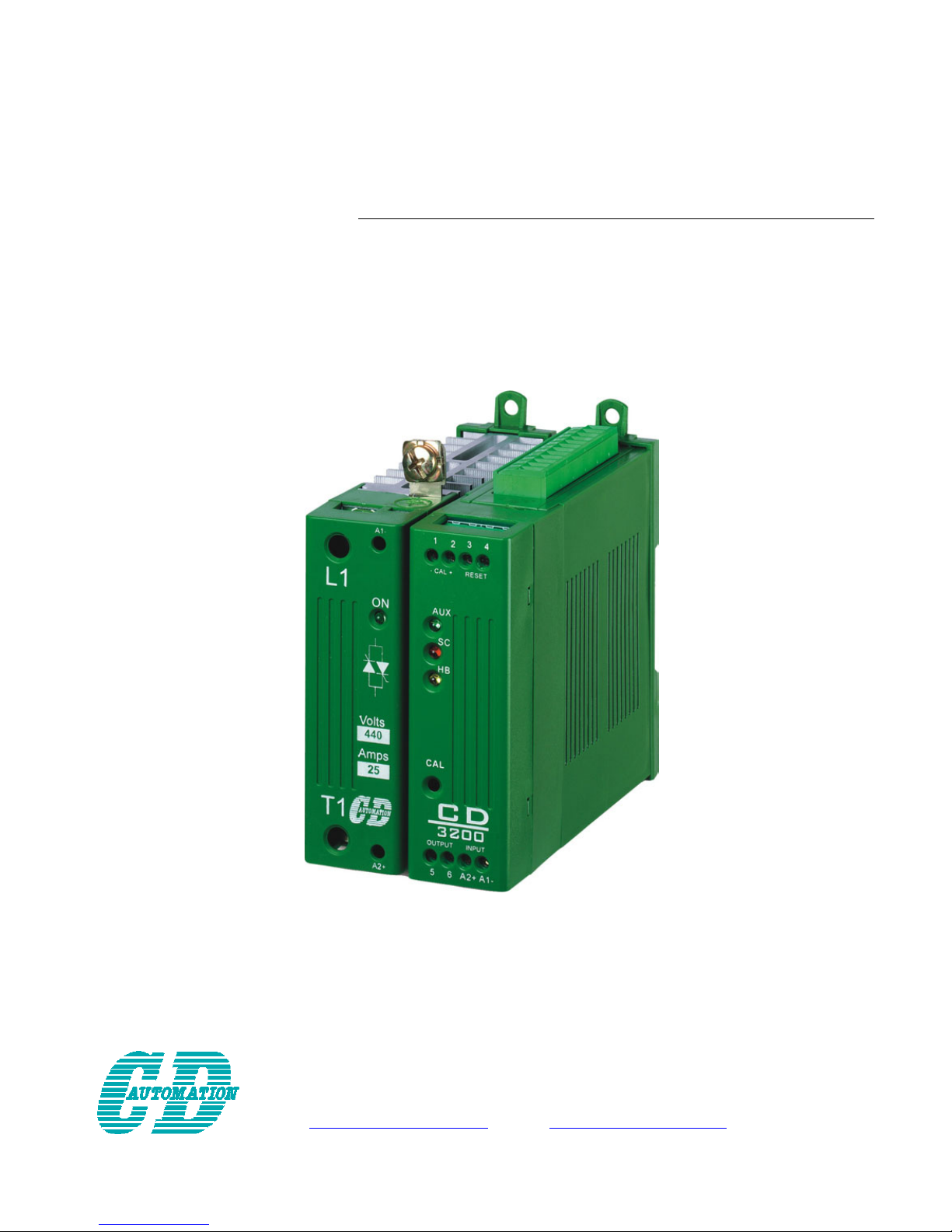
CD3200
Thyristor Unit
from 15A to 110A
Page 2

Page 3

SUMMARY
1 Important warnings for safety..................................................................................... 5
2 Introduction ................................................................................................................ 7
2.1 Advantages compared with analog thyristor unit 7
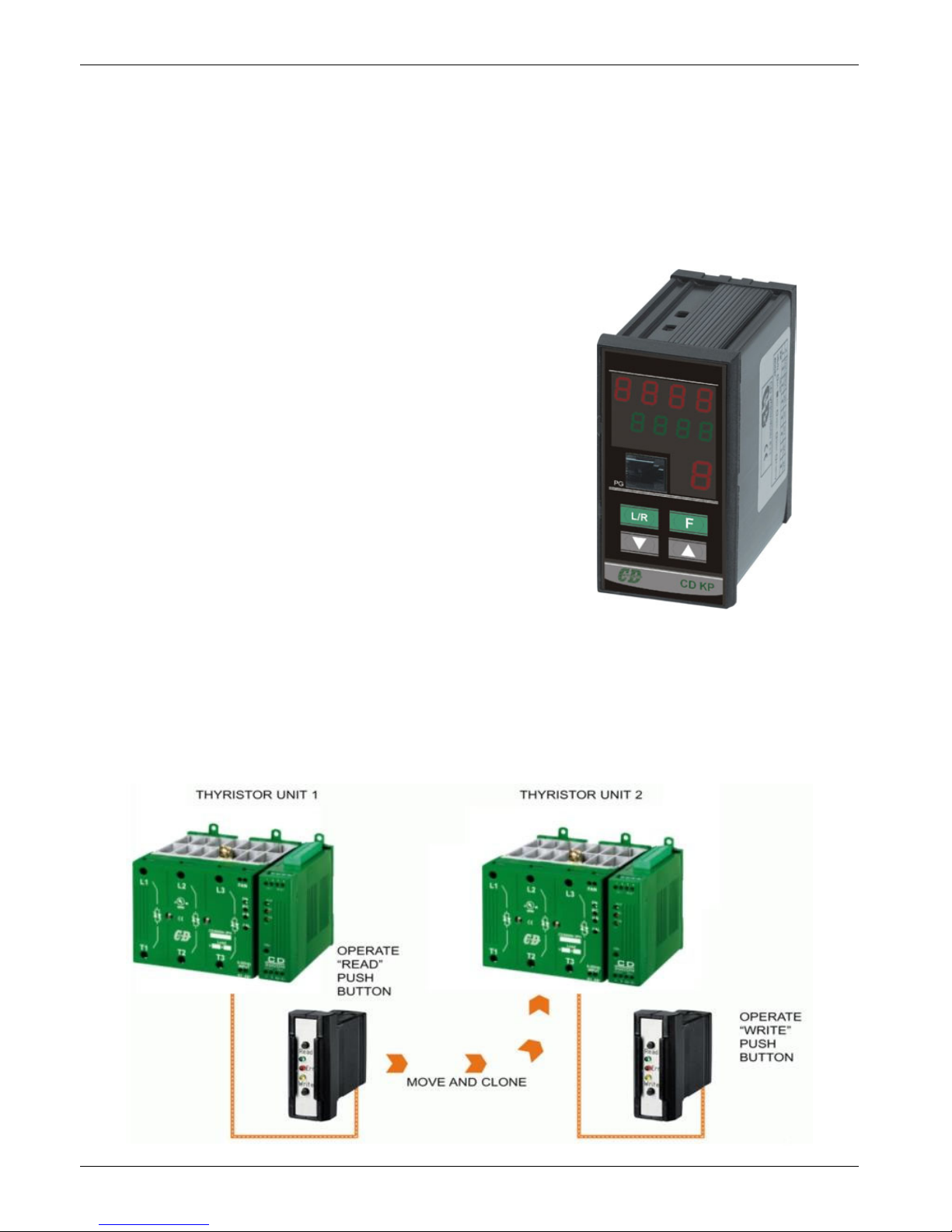
2.2 CD-KP 8
2.3 CD-EASY 8
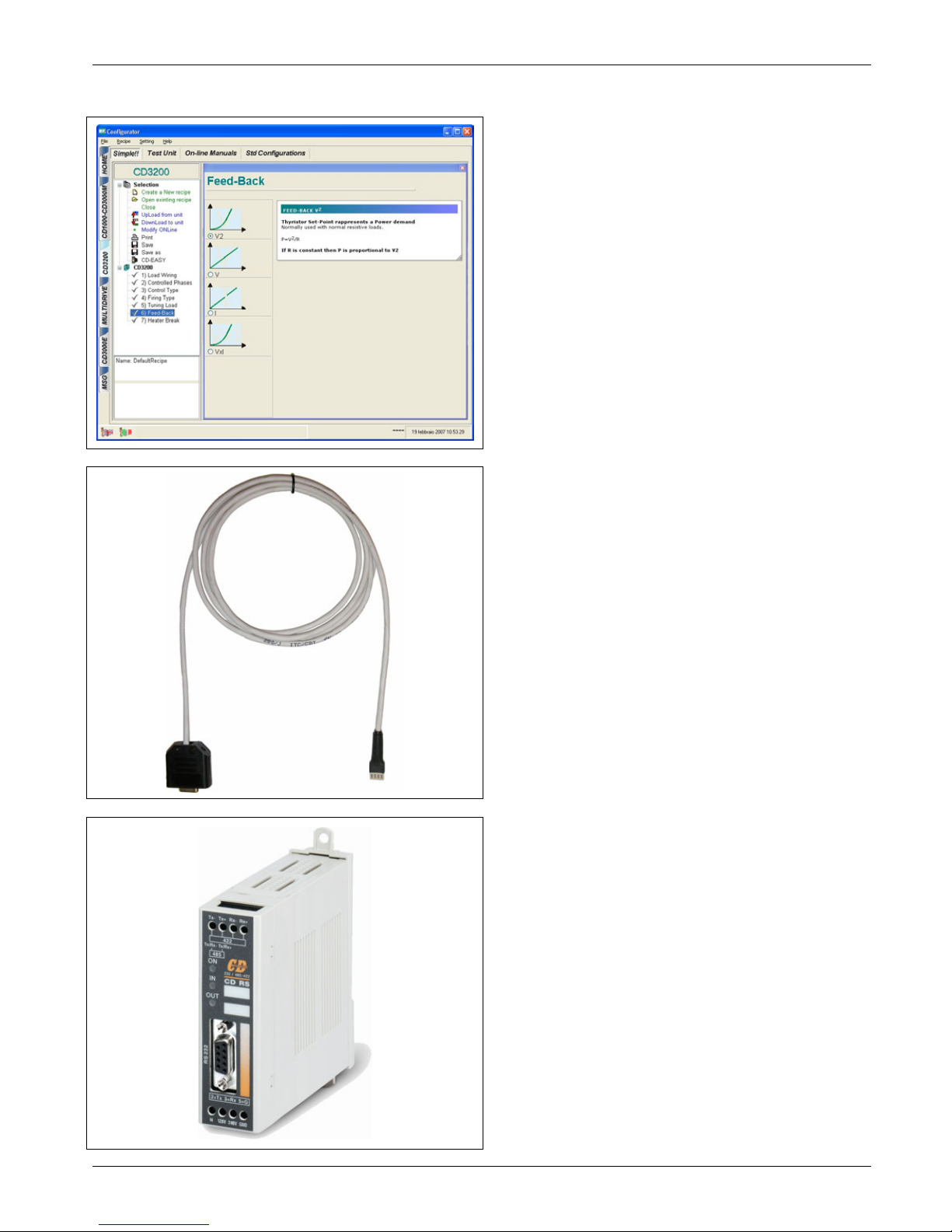
2.4 Software Configurator 9
3 Quick Start ................................................................................................................ 10
4 CD3200 Sizing ........................................................................................................... 10
5 Identification and Order Code.................................................................................... 11
5.1 Identification of the unit 11
5.2 Order Code 12
6 Installation................................................................................................................ 13
6.1 Environmental installation conditions 13
6.2 Dimensions and Weight 14
6.3 CT dimensions 14
6.4 Fixing holes 15
7 Wiring instructions .................................................................................................... 16
7.1 Removing the cover 16
7.2 Wiring details 17
7.3 Power Terminals 18
7.4 Command Terminals 18
7.5 Diagram of control connection from size 15A to 25A 19
7.6 Diagram of control connection from size 35A to 45A 20
7.7 Diagram of control connection from size 60A to 110A 21
8 Power output features ............................................................................................... 22
8.1 Derating curve 22
8.2 Cooling fans 22
9 Led status and Alarms ...............................................................................................23
9.1 LED Status Table 23
9.2 Not Critical Alarm 23
9.3 Calibration Procedure 24
10 Firing type ............................................................................................................... 24
10.1 Phase Angle (PA) 25
10.2 Soft Start with Phase Angle (S+PA) 25
10.3 Action of the Limit Current 26
10.4 Feed-back type 27
Page 4

11 Connection description ............................................................................................ 28
11.1 Access to the Electronic boards 28
11.2 Supply the Electronic Board 29
11.3 Analog Inputs 30
11.4 Digital Input 32
11.5 Digital Output 34
11.6 PG Connector 35
11.7 RS485 Serial Port 35
11.8 Address configuration 36
12 MODBUS communication ......................................................................................... 37
12.1 MODBUS RTU Protocol 37
12.2 Message Format 37
12.3 Read Holding Registers 39
12.4 Preset Multiple Registers 39
12.5 Error and exception responses 40
13 Configuration Parameters........................................................................................ 41
14 FuseHolder and Fuses.............................................................................................. 44
14.1 FuseHolder size 44
14.2 Fuses and Fuse Code for UL 45
14.3 Fuses and Fuse Code for CE 46
15 Maintenance ............................................................................................................ 47
15.1 Trouble Shooting 47
15.2 Fans 48
15.3 Maintenance 48
15.4 Repairing procedure 48
15.5 Warranty condition 48
16 Note ........................................................................................................................ 49
Page 5
CD Automation srl CD3200-1PH from 15A to 110A User’s Manual
5
1 Important warnings for safety
This chapter contains important information for the safety. The not observance of these instructions may
result in serious personal injury or death and can cause serious damages to the Thyristor unit and to the
components system included.
The installation should be performed by qualified persons.
The Thyristor unit are integral part of industrial equipments. When it is supply, the
Thyristor unit is subject to dangerous tensions.
• Don't remove the protection Cover.
• Don't use these unit in aerospace applications and/ or nuclear.
The nominal current corresponds to use at temperature not superior to 40°C.
• The Thyristor unit must be mounted in vertical position and without obstruction above
and below to allow a good flow ventilation.
• The hot air of one thyristor unit must not invest the unit positioned above.
• For side by side placed leave a space of 15mm between the unit.
A suitable device must ensure that the unit can be electrically isolated from the supply, this
allows the qualified people to work in safety.
Protection (Protection, Protezione)
The unit have IP20 protection rating as defined by the specific international. Is necessary
consider the place of installation.
Earth (Terre, Messa a terra)
For safety, the Thyristor unit with isolated heat-sink must be connected to earth.
Earth impedance should be correspondent to local earth regulation. Periodically the earth
efficiency should be inspected.
Electronic supply (Alimentation électronique, Alimentazione elettronica)
The electronic circuit of the Thyristor unit must be supplied by dedicated voltage for all
electronic circuits and not in parallel with coil contactors, solenoids and other.
It's recommended to use a shielded transformer.
Electric Shock Hazard (Risque de choque électrique, Rischi di scosse elettriche)
When the Thyristor unit is energized, after the power supply is shut off, wait least a minute
for allow the discharge of the internal capacitors where there is a dangerous tension. Before
working, make sure that:
• Only authorized personnel must perform maintenance, inspection, and replacement
operations.
• The authorized personnel must read this manual before to have access to the unit.
• Unqualified People don't perform jobs on the same unit or in the immediate vicinities.
Page 6
CD Automation srl CD3200-1PH from 15A to 110A User’s Manual
6
Important warnings (Attention, Avvertenze importanti)
During the operations with units under tension, local regulations regarding electrical
installation should be rigidly observed:
• Respect the internal safety rules.
• Don't bend components to maintain insulation distances.
• Protect the units from high temperature humidity and vibrations.
• Don't touch components to prevent electrostatic discharges on them.
• Verify that the size is in line with real needs.
• To measure voltage current etc. on unit, remove rings and other jewels from fingers
and hands.
• Authorized personnel that work on thyristor unit under power supply voltage must be
on insulated board
This listing does not represent a complete enumeration of all necessary safety cautions.
Electromagnetic compatibility
(Compatibilità électromagnétique, Compatibilità elettromagnetica)
Our thyristor units have an excellent immunity to electromagnetic interferences if all
suggestions contained in this manual are respected. In respect to a good Engineering
practice, all inductive loads like solenoids contactor coils should have a filter in parallel.
Emissions (Emission, Emissioni)
All solid-state power controllers emit a certain amount of radio-frequency energy because of
the fast switching of the power devices.
The CD Automation’s Thyristor unit are in accord with the EMC norms, CE mark.
In most installations, near by electronic systems will experience no difficulty with
interference. If very sensitive electronic measuring equipment or low-frequency radio
receivers are to be used near the unit, some special precautions may be required. These
may include the installation of a line supply filter and the use of screened (shielded) output
cable to the load.
Note
Warning: This icon is present in all the operational procedures where the Improper
operation may result in serious personal injury or death
Caution: This icon is present in all the operational procedures where the Improper
operation can cause damage for the Thyristor unit.
CD Automation reserves the right to modify the own products and this manual without any
advise.
CUS
LISTED
U
L
®
Page 7
CD Automation srl CD3200-1PH from 15A to 110A User’s Manual
7
2 Introduction
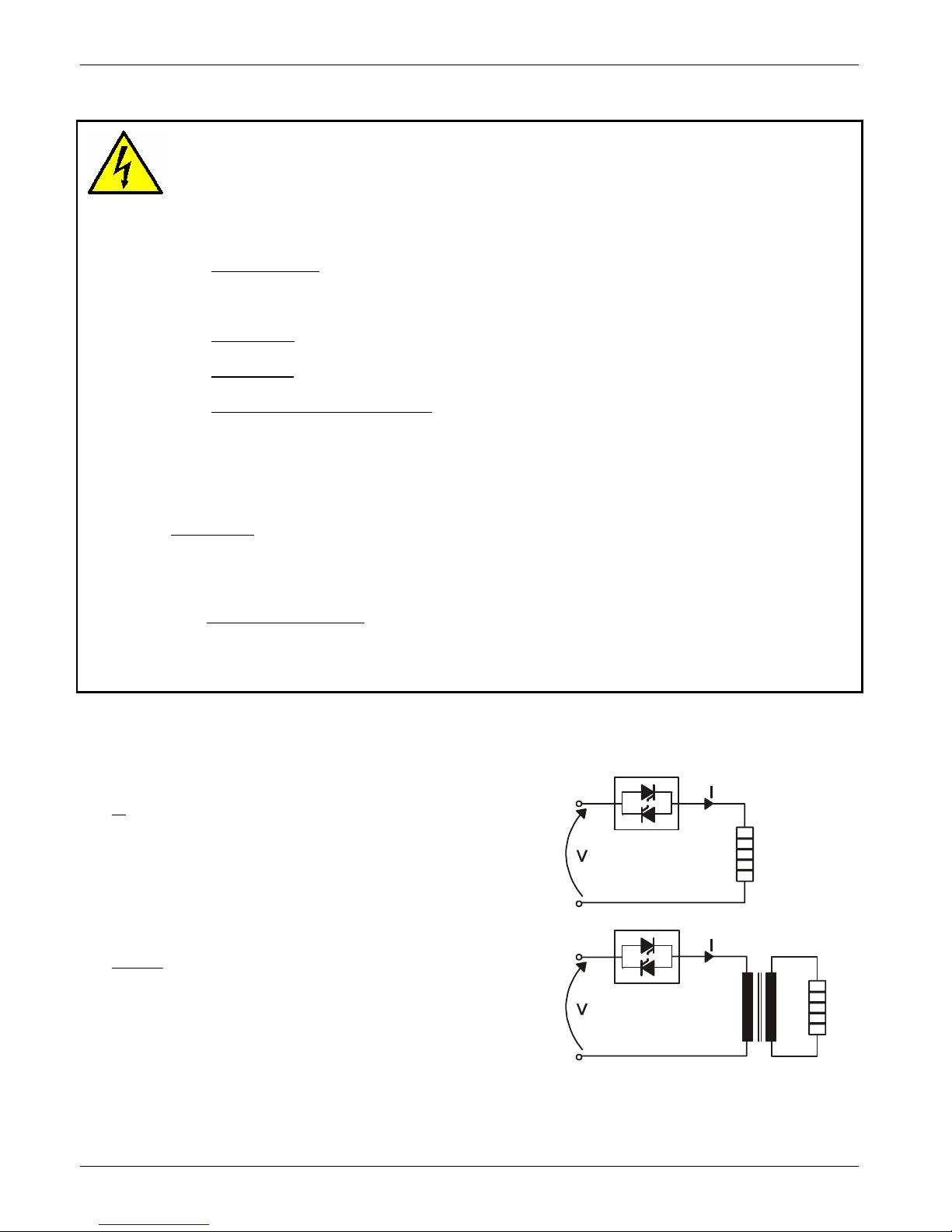
A thyristor unit is semiconductor device which acts as a switch formed by two thyristors in ant parallel.
To switch on the alternating current the input signal will be on and the thyristor will switch off at first
Zero Crossing voltage with no input signal.
The benefits of thyristor units compared with elettromechanical contactors are numerouses: no moving
parts, no maintenance and capacity to switch very fast. Thyristors are the only solution to control
transformers and special loads that change resistance with temperature and with age.
Load
Thyristor
2.1 Advantages compared with analog thyristor unit
Communication RS485 is a standard feature of CD3200 this allows the use of many information like:
current, power, load state and all the parameters for diagnostic and configuration. Ulterior advantages of
the digital system vs the analogical is the flexibility and the possibility of implement special
characteristics without change the hardware. Several strategies can be implemented and selected
through the configuration parameters.
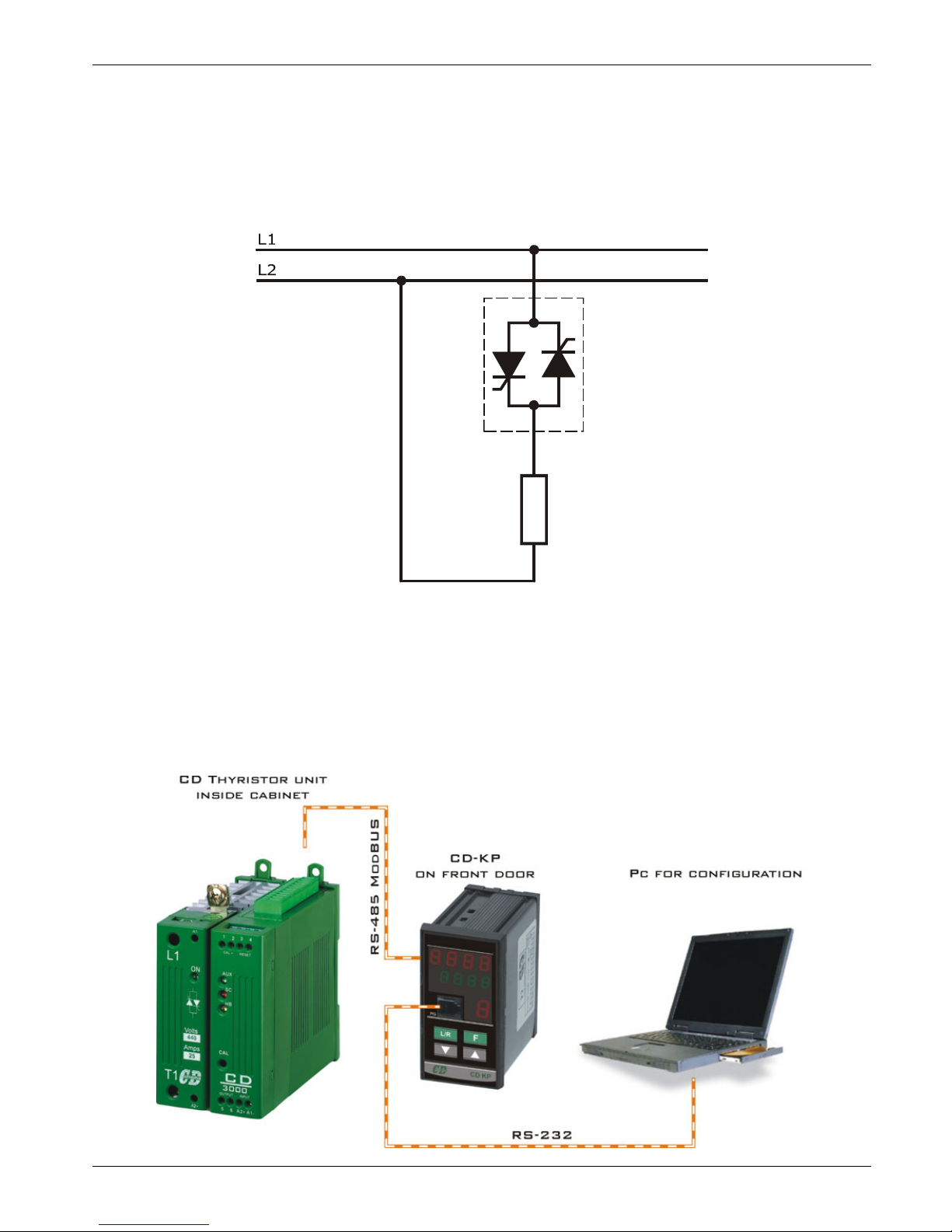
With CD-KP, you can have access to the configuration parameters without expose at the dangerous
voltage inside the cabinet and without stop the plant.
Page 8
CD Automation srl CD3200-1PH from 15A to 110A User’s Manual
8
2.2 CD-KP
The CD-KP is designed to be connected with all CD Automation's Thyristor units via RS485
communication. On front unit is possible to read the principal operational parameters of the unit like:
power, tension, current, reference, alarms, etc.
One of these variables can be selected and retransmitted via an isolated output (4÷20mA or 0÷10V)
All the menus (except the operator menu) can be protected by password to avoid accidental change of
configuration parameters by unauthorised personnel.
On front unit is also available a plug-in connector RS485 for connect a PC with the Thyristor units
without open the cabinet and without stop the production process.
Technical Specification:
• Use in Local/Remote
• Set Point Ramp UP - Down
• Scroll selection of:
- Set point
- Power output
- Current
- Voltage
• Display indication for:
- Heater Break alarm
- SCR short circuit
• Password for configuration parameters
• Plug-in connector on front to use software configurator
• Retransmission (4-20mA or 0-10Vdc) of one of these
parameters: Power PV, Current, Voltage.
• Dimension 48x96x92mm (LxAxP)
• Comply with EMC, CE marked
2.3 CD-EASY
CD-EASY is a Memory of support used for maintenance people that is not confident in personal
computer.
With the CD-EASY is possible memorize the configuration of one Thyristor Unit and paste it into another
in few seconds.
CD-EASY could be loaded with the personal configuration of the unit and stored together with the
system drawings in a convenient place, enabling unit reconfiguration within seconds if require.
Page 9
CD Automation srl CD3200-1PH from 15A to 110A User’s Manual
9
2.4 Software Configurator
The software configuration is free and is possible
download it from our site:
www.cdautomation.com
If the Order Code is in line with requirement, then
CD3200 has been already configured in Factory
and it's ready to use.
You need the software only to modify the ordered
configuration. Anyway we suggest to check the
unit on the machine with the "Test unit" section.
For install the software, launch the program and
follow the instructions on the screen.
To connect the unit at the PC, it's necessary use
the programming cable connected between the PG
connector (see par. 11.6) and the serial port
RS232 of the PC.
The programming cable is not included.
With the CD-RS serial converter is possible
configure the Thyristor unit also through the
RS485 (see par. 11.7).
For this solution, the programming cable is not
necessary.
Run the software configurator and set the serial
port of the PC with con baudrate =9600 and the
address of Thyristor unit (default=1).
Page 10
CD Automation srl CD3200-1PH from 15A to 110A User’s Manual
10
3 Quick Start
Caution: this procedure must be performed only by qualified persons.
If the Order Code of the Thyristor unit is in line with what you really need, then CD3200 has been
already configured in Factory and you just need to do the following steps:
1. Verify the CD3200 Sizing
. Making sure that:
• The load current is equal or less than the MAX current of CD3200.
• The load voltage is equal or less than the MAX voltage of CD3200.
(see par. 4)
2. Verify the Order Code
(see par. 5.2)
3. Verify the Installation
(see par. 6)
4. Verify the Diagram of control connection
:
• All auxiliary connections must be done in line with wirings on this manual.
• Verify that there isn’t a short circuit on the load.
• Verify that the Reset Contact on terminal 3 and 4 are closed.
• With External Enable option give Enable to the unit.
(see par. 7.5)
5. Supply the Electronic boards
(see Order Code
)
6. Supply the Fan at 230VAC ±15% 50/60Hz (110VAC ±15% 50/60Hz Optional)
(only for size S8C)
7. Supply the Power unit
(see par. 7.3)
8. Make the Calibration procedure
(see par. 9.3)
The CD3200 Thyristor unit is ready to start.
4 CD3200 Sizing
4.1.1 Wiring with resistive load
V
P
I =
V = Nominal voltage phase to phase
I = Nominal current to the load
P = Nominal power to the load
4.1.2 Wiring with inductive load
φ
cosV
P
I =
V = Nominal voltage phase to phase
I = Nominal current to the load
P = Nominal power to the load
Page 11
CD Automation srl CD3200-1PH from 15A to 110A User’s Manual
11
5 Identification and Order Code
5.1 Identification of the unit
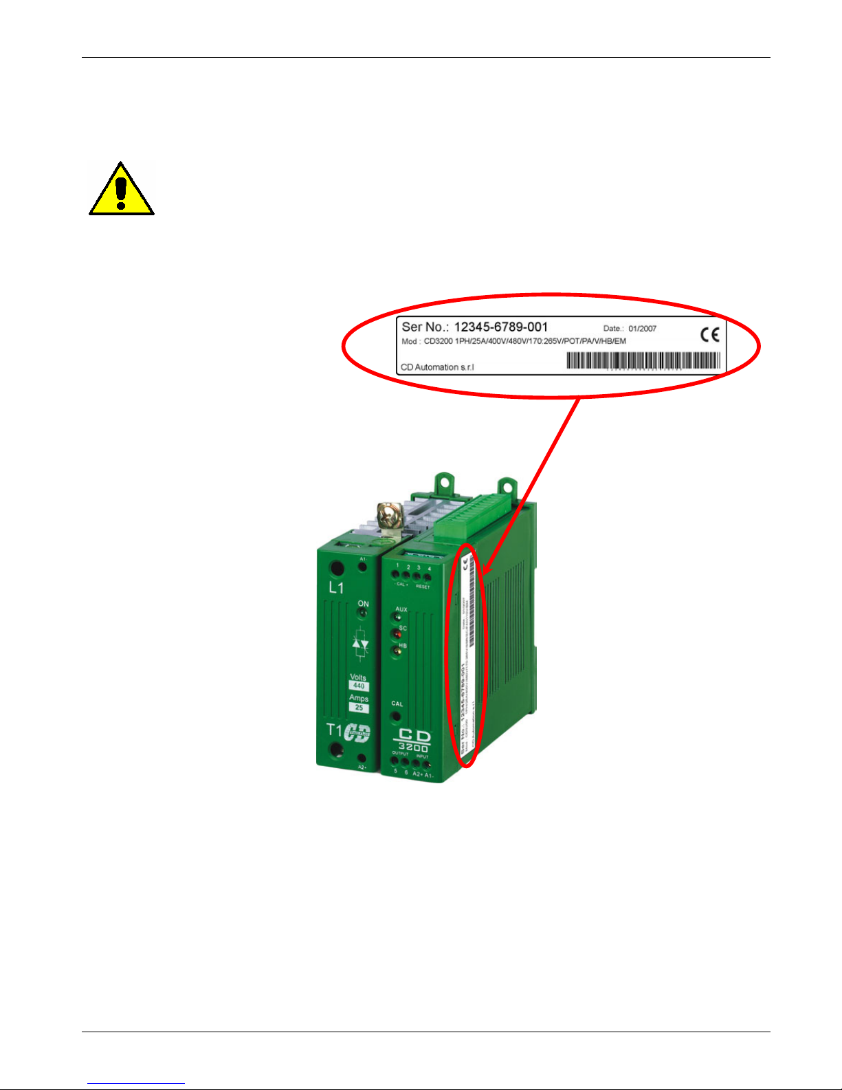
Caution: Before to install, make sure that the Thyristor unit have not damages. If the
product has a fault, please contact the dealer from which you purchased the product.
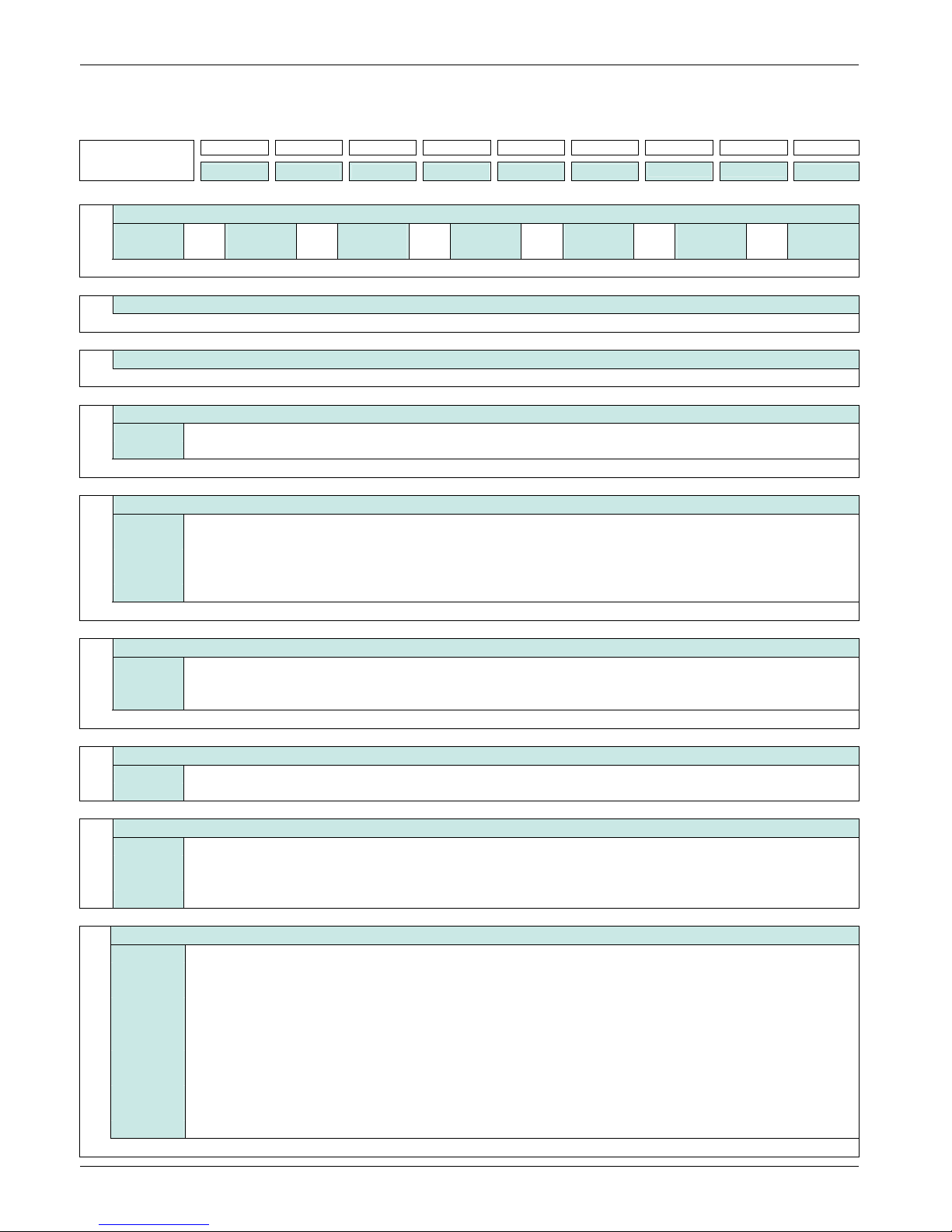
The identification's label give all the information regarding the factory settings of the Thyristor unit, this
label is on the unit, like represented in figure.
Verify that the product is the same thing as ordered (see par. 5.2).
Page 12
CD Automation srl CD3200-1PH from 15A to 110A User’s Manual
12
5.2 Order Code
Model 1 2 3 4 5 6 7 8 9
CD3200
1
Max Current of CD3200
15A 35A 60A 110A
25A 45A 90A
The Max Current must be equal or more than Load Current
2
Load Current
Specify this value to configure the unit in CD Automation
3
Load Voltage
Specify this value to configure the unit in CD Automation
4
Max Voltage of CD3200
480V
600V
The Max Voltage must be equal or more than Load Voltage
5
Auxiliary Voltage (Voltage supply for the Electronic boards)
90:130 From 90 to 130Vac; 10VA
170:265 From 170 to 265Vac; 10VA
230:345 From 230 to 345Vac; 10VA
300:530 From 300 to 530Vac; 10VA
510:690 From 510 to 690Vac; 10VA
6
Input
0÷10V 0÷10Vdc
4÷20mA 4÷20mA
POT Potentiometer 10KΩ
7
Firing Type
S+PA Soft Start + Phase Angle
PA Phase Angle
8
Feed Back
V Voltage
I Current
V2 Voltage square
VxI Power (VxI)
9
Option
NCL No current limit
CLP External current limit profiling (0÷10Vdc)
EN Opto isolated external enable
FBS Opto isolated Feed-back Selection
EF External fuses and fuse holders
NF No fuses
HB Heater Break Alarm
CD-KP External Keypad
110Fan Fan voltage supply 110VAC ± 15% (std 230VAC ± 15%) 50/60Hz
EP External Protection IP20 for size S7C and S8C
UL UL Certification
Page 13
CD Automation srl CD3200-1PH from 15A to 110A User’s Manual
13
6 Installation
Caution: Don't install near the hot elements or near the units that could give
electromagnetic interferences.
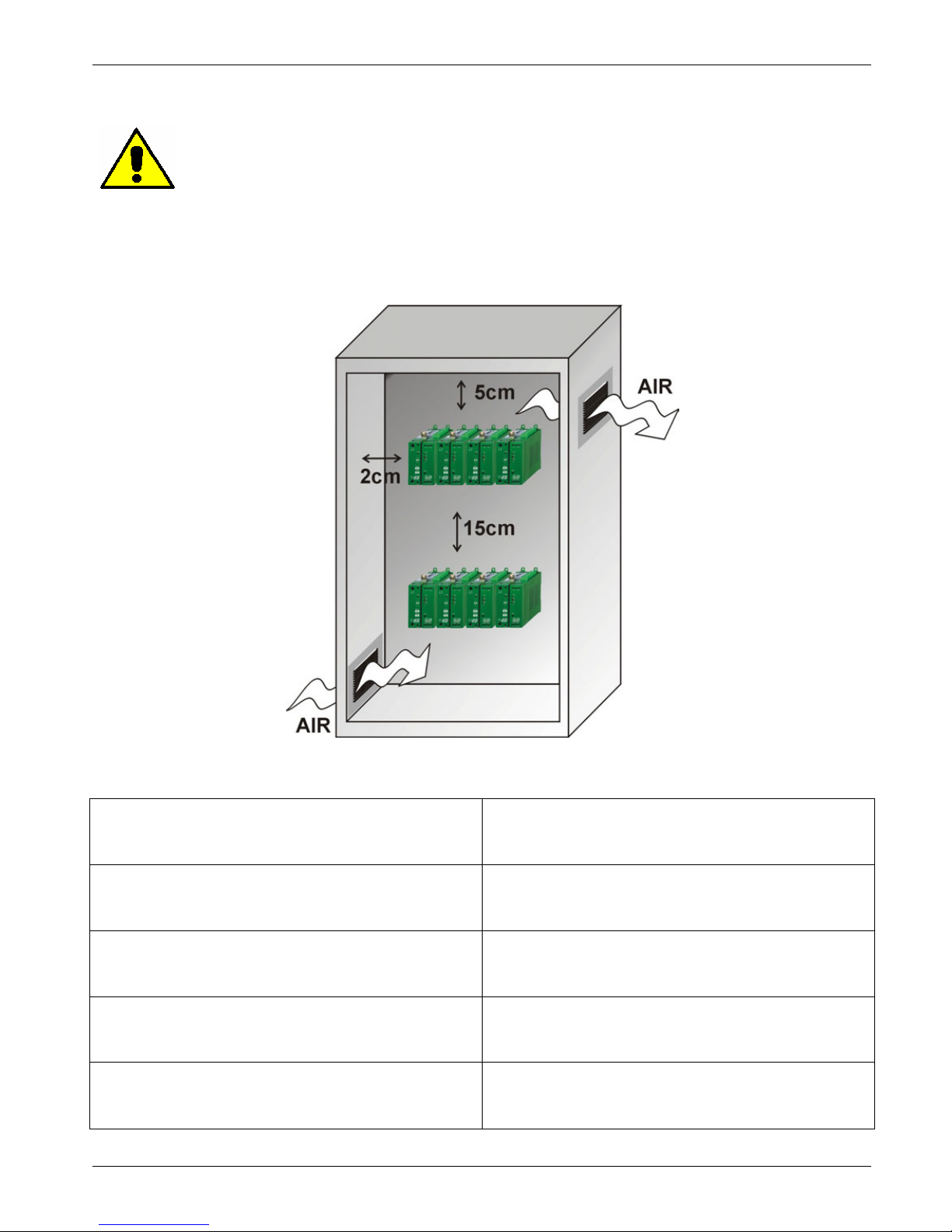
The CD3200 Thyristor unit must be always mounted in vertical position to improve air cooling on heatsink. Maintain the minimum distances in vertical and in horizontal as represented.
When more unit has mounted inside the cabinet maintain the air circulation like represented in figure.
Sometimes is necessary installing a fan to have better air circulation.
6.1 Environmental installation conditions
Ambient temperature
0-40°C at nominal current. Over 40°C use the
derating curve (see par. 8.1)
Storage temperature -25°C to 70°C
Installation place
Don’t install at direct sun light, where there are
conductive dust, corrosive gas, vibration or water
and also in salty environmental.
Altitude
Up to 1000 meter over sea level. For higher
altitude reduce the nominal current of 2% for each
100m over 1000m
Humidity From 5 to 95% without condense and ice
Page 14
CD Automation srl CD3200-1PH from 15A to 110A User’s Manual
14
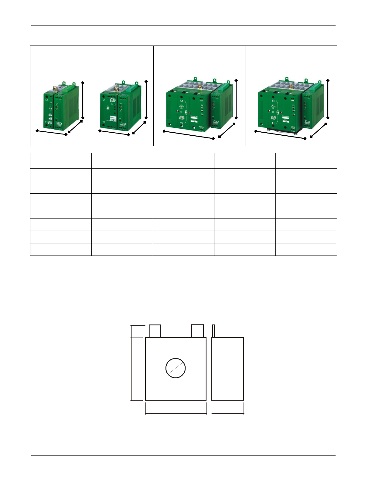
6.2 Dimensions and Weight
CD3200
15A÷25A (S0C)
CD3200
35A÷45A (S3C)
CD3200
60A÷90A (S7C)
CD3200
110A (S8C)
Size W(mm) H(mm) D(mm) Weight (kg)
15A (S0C) 63 120 120 0,7
25A (S0C) 63 120 120 0,7
35A (S3C) 85 120 120 0,95
45A (S3C) 85 120 120 0,95
60A (S7C) 148 120 159 2
90A (S7C) 148 120 159 2
110A (S8C) 148 138 159 2,15
6.3 CT dimensions
8
1
2
39
39 20
D
H
W
D
H
W
D
H
W
D
H
W
Page 15
CD Automation srl CD3200-1PH from 15A to 110A User’s Manual
15
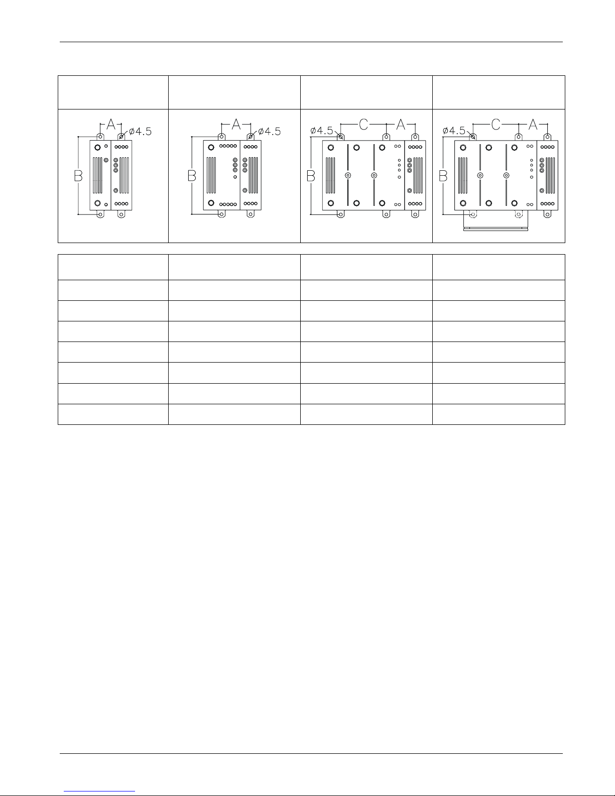
6.4 Fixing holes
CD3200
15A÷25A (S0C)
CD3200
35A÷45A (S3C)
CD3200
60A÷90A (S7C)
CD3200
110A (S8C)
Size A(mm) B(mm) C(mm)
15A (S0C) 30 110 -
25A (S0C) 30 110 -
35A (S3C) 41 110 -
45A (S3C) 41 110 -
60A (S7C) 41 110 65
90A (S7C) 41 110 65
110A (S8C) 41 110 65
Page 16
CD Automation srl CD3200-1PH from 15A to 110A User’s Manual
16
7 Wiring instructions
Caution: this procedure must be performed only by qualified persons.
The Thyristor unit could be susceptible to interferences lost by near equipments or by the power supply,
for this reason in accord to the fundamental practices rules is opportune take some precautions:
• The electronic circuit of the Thyristor unit must be supplied from a dedicated voltage and not with
inductive or capacitive loads. We recommend the use of a screened transformer.
• The coil contactor, the relays and other inductive loads must be equipped with opportune RC filter.
• Use shielded bipolar cables for all the input and output signals.
• The signal cables must not be near and parallel to the power cables.
• Local regulations regarding electrical installation should be rigidly observed.
For safety connect the heat-sink to the earth with his terminal.
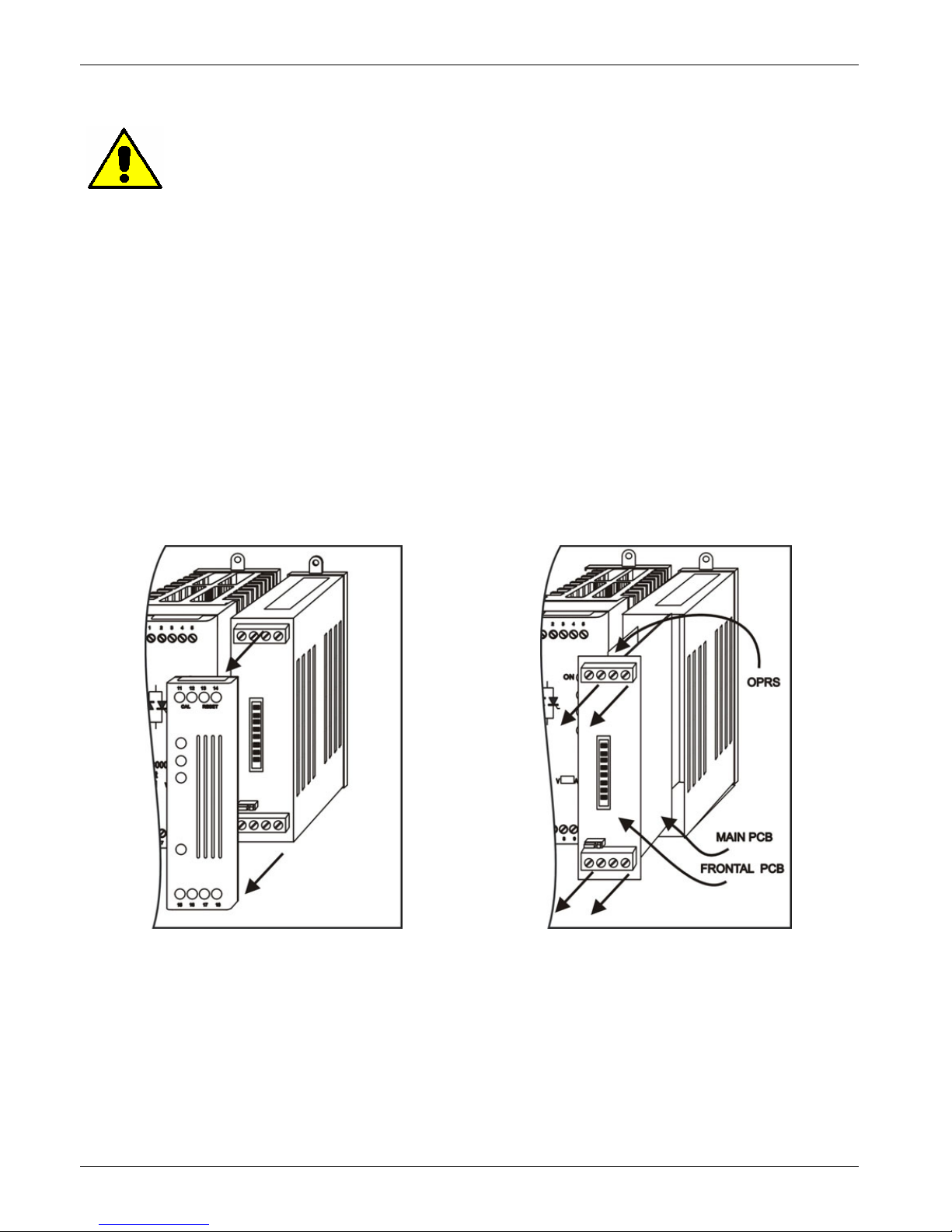
7.1 Removing the cover
Remove plastic Cover For all size To remove the board Pull the PCB
Page 17
CD Automation srl CD3200-1PH from 15A to 110A User’s Manual
17
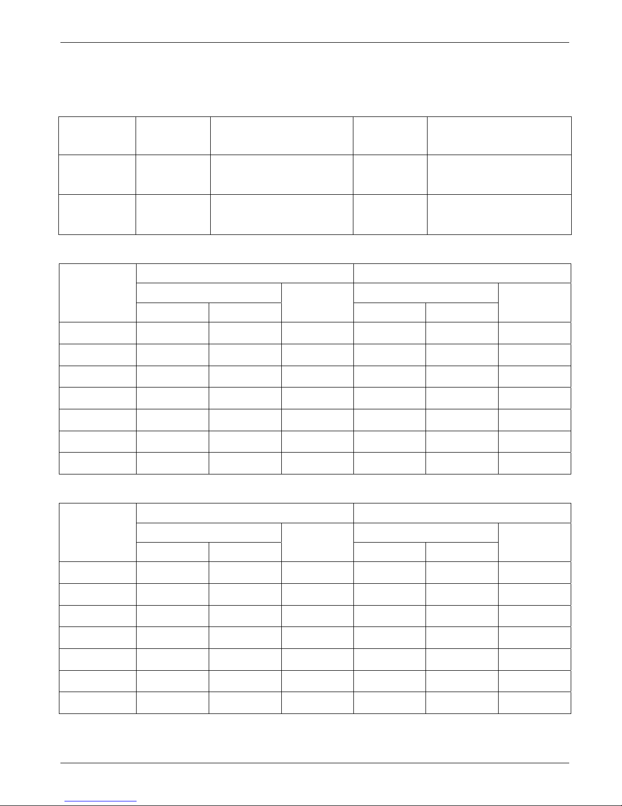
7.2 Wiring details
Use copper cables and wires rated for use at 75°C only.
7.2.1 Power cable torque (suggested)
Current
Connector
Type
Torque
Lb-in (N-m)
Wire
Range
AWG / kcmil
Wire
Terminal
15A,25A
35A,45A
M5 Screw 26.6 (3.0) 8
UL Listed (ZMVV)
Wire Pin
60A,90A
110A
M6 Screw 70.8 (8.0) 1
UL Listed (ZMVV)
Fork/Spade Terminal
Copper Tube Crimp. Lug
7.2.2 Power cable dimensions (suggested)
Supply Load
Current Cable Screw Cable Screw
mm² AWG M mm² AWG M
15A (S0C) 4 12 M5 4 12 M5
25A (S0C) 6 10 M5 6 10 M5
35A (S3C) 10 8 M5 10 8 M5
45A (S3C) 10 8 M5 10 8 M5
60A (S7C) 16 6 M6 16 6 M6
90A (S7C) 35 3 M6 35 3 M6
110A (S8C) 35 3 M6 35 3 M6
7.2.3 Cable dimensions (suggested) of Earth and of the Command Terminals
Earth Command Terminals
Current Cable Screw Cable
mm² AWG M mm² AWG
15A (S0C) 4 12 M5 0,50 18
25A (S0C) 6 10 M5 0,50 18
35A (S3C) 6 10 M5 0,50 18
45A (S3C) 6 10 M5 0,50 18
60A (S7C) 6 10 M5 0,50 18
90A (S7C) 6 10 M5 0,50 18
110A (S8C) 6 10 M5 0,50 18
Page 18
CD Automation srl CD3200-1PH from 15A to 110A User’s Manual
18
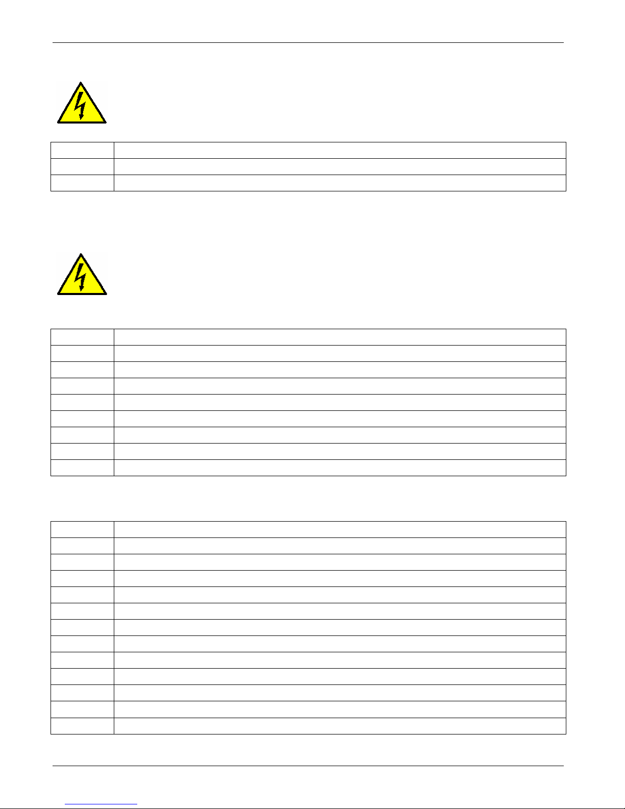
7.3 Power Terminals
Warning: Before connecting or disconnecting the unit check that power and control cables
are isolated from voltage sources.
Terminal Description
L1 Line Input Phase 1
T1 Load Output Phase 1
7.4 Command Terminals
Warning: Before connecting or disconnecting the unit check that power and control cables
are isolated from voltage sources.
7.4.1 Upper Terminal
Terminal Description
1 (-) External Calibration 24 Vdc max
2 (+)External Calibration 24 Vdc max
3 Reset
4 Reset
5 (+) CD32000 Output Command signal (Internal Connections)
6 (-) CD3200 Output Command signal (Internal Connections)
A2+ (+) Input command signal 0÷10V,4÷20mA,POT
A1- (-) Input command signal 0÷10V,4÷20mA,POT
(see par. 11.1)
7.4.2 Lateral Terminal
Terminal Description
7 RS485 A
8 RS485 B
9 Output +8Vdc stabilized 1 mA MAX
10 HB relay contact (Max 500mA , 125Vac) Optional
11 HB relay contact (Max 500mA , 125Vac) Optional
12 External current limit profiling
13 Current Transformer “CT1” input
14 Current Transformer “CT1” input
15 Not connected
16 Voltage Supply for Electronic Boards (Auxiliary)
17 Earth
18 Voltage Supply for Electronic Boards (Auxiliary)
(see par. 11.1)
Page 19
CD Automation srl CD3200-1PH from 15A to 110A User’s Manual
19
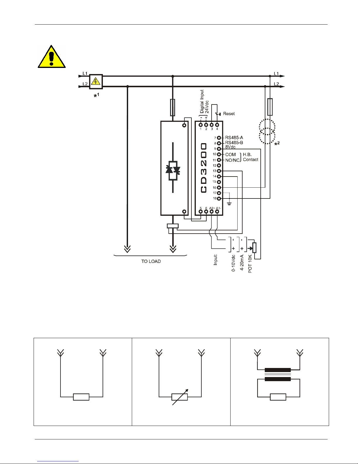
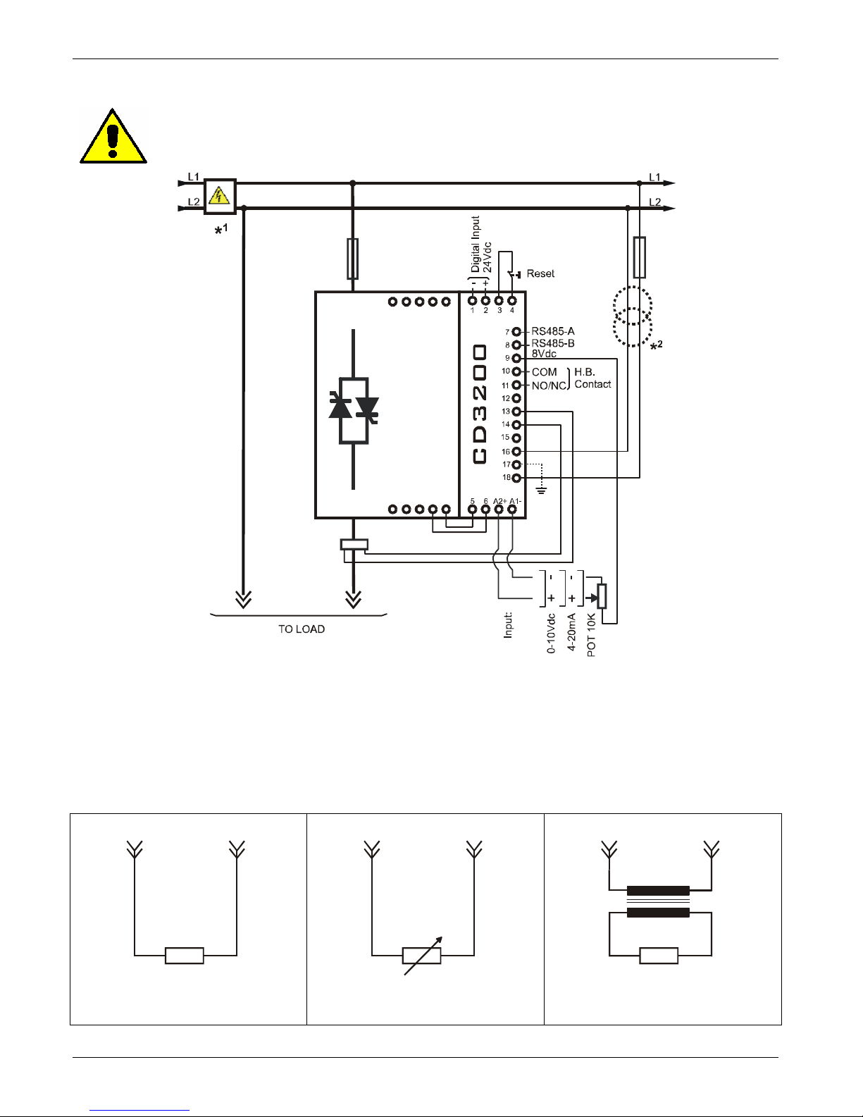
7.5 Diagram of control connection from size 15A to 25A
Caution: this procedure must be performed only by qualified persons.
CT1
L1
T1
POWER UNIT
A1-A
2+
NOTE:
• * The user installation must be protecting by electromagnetic circuit breaker or by fuse isolator.
• *² The auxiliary voltage supply of the CD3200 unit must be synchronized with load voltage power
supply. If the Auxiliary Voltage (written on the identification label) is different from Supply Voltage
(to the load), use an external transformer as designated.
• To work, the Reset Contact on terminal 3 and 4 must be closed.
Load Type
L2 T1
L2 T1
L2 T1
Resistances and
Infrared Lamps
Variable Resistances
Super kanthal or Silicon carbide
elements
Transformers and
Inductances
Page 20
CD Automation srl CD3200-1PH from 15A to 110A User’s Manual
20
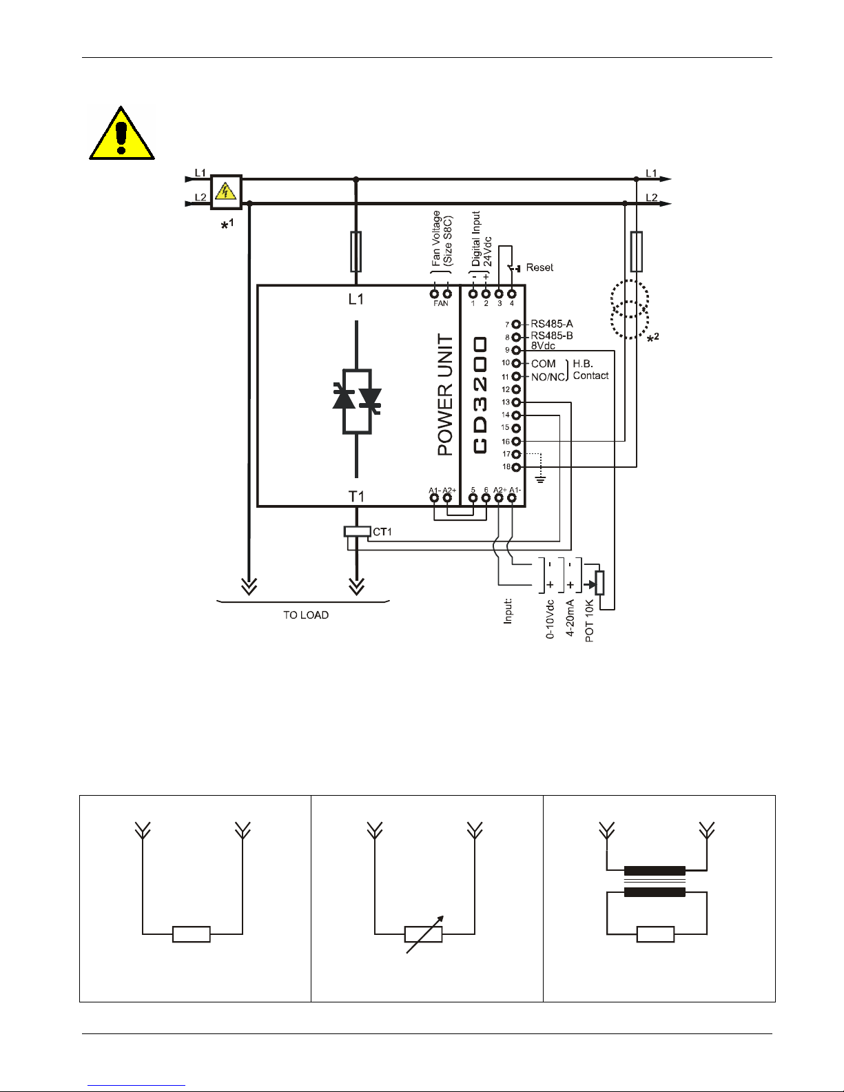
7.6 Diagram of control connection from size 35A to 45A
Caution: this procedure must be performed only by qualified persons.
POWER UNIT
L1
CT1
T1
A2+A
1-
NOTE:
• * The user installation must be protecting by electromagnetic circuit breaker or by fuse isolator.
• *² The auxiliary voltage supply of the CD3200 unit must be synchronized with load voltage power
supply. If the Auxiliary Voltage (written on the identification label) is different from Supply Voltage
(to the load), use an external transformer as designated.
• To work, the Reset Contact on terminal 3 and 4 must be closed.
Load Type
L2 T1
L2 T1
L2 T1
Resistances and
Infrared Lamps
Variable Resistances
Super kanthal or Silicon carbide
elements
Transformers and
Inductances
Page 21
CD Automation srl CD3200-1PH from 15A to 110A User’s Manual
21
7.7 Diagram of control connection from size 60A to 110A
Caution: this procedure must be performed only by qualified persons.
NOTE:
• * The user installation must be protecting by electromagnetic circuit breaker or by fuse isolator.
• *² The auxiliary voltage supply of the CD3200 unit must be synchronized with load voltage power
supply. If the Auxiliary Voltage (written on the identification label) is different from Supply Voltage
(to the load), use an external transformer as designated.
• To work, the Reset Contact on terminal 3 and 4 must be closed.
Load Type
L2 T1
L2 T1
L2 T1
Resistances and
Infrared Lamps
Variable Resistances
Super kanthal or Silicon carbide
elements
Transformers and
Inductances
Page 22
CD Automation srl CD3200-1PH from 15A to 110A User’s Manual
22
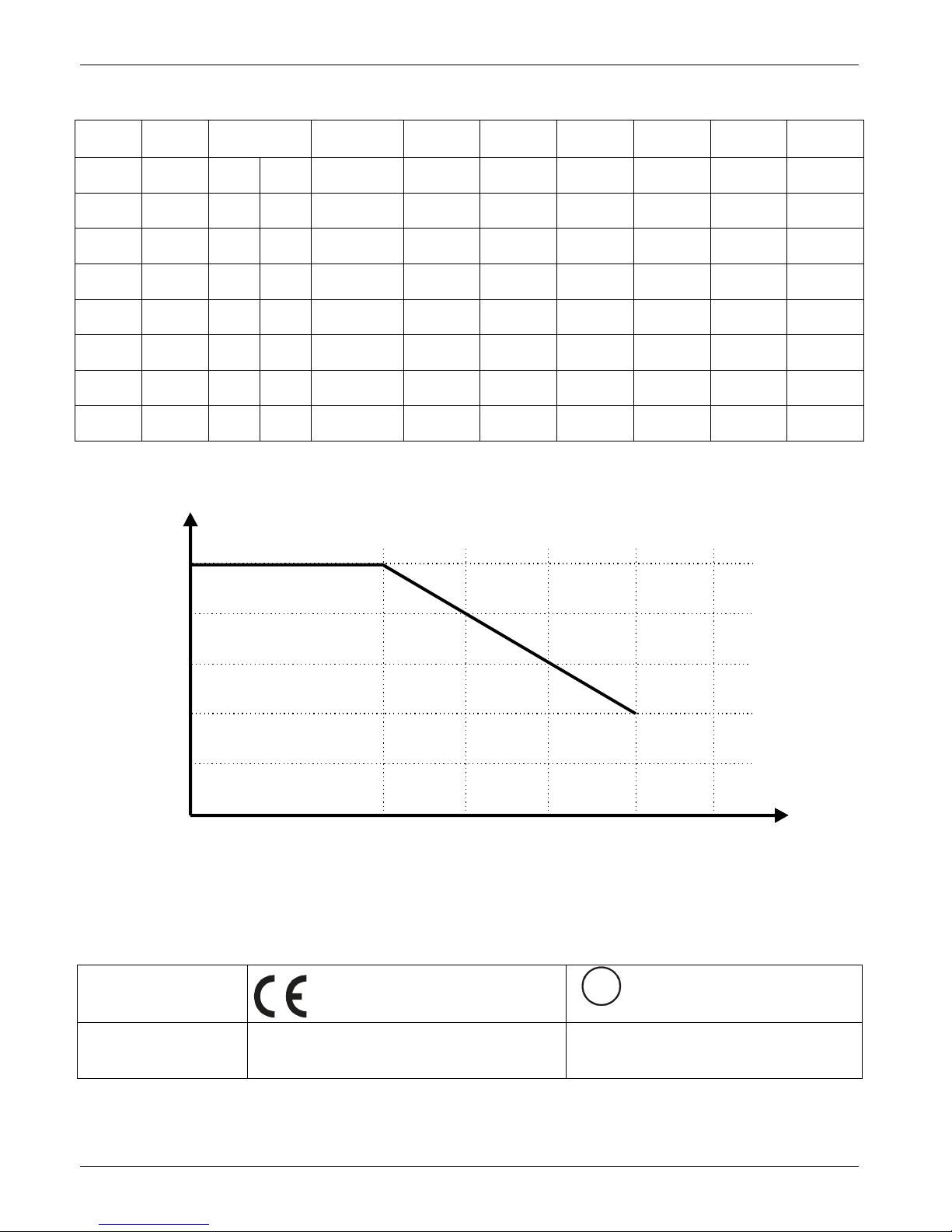
8 Power output features
Current
Voltage
range
Repetitive peak
reverse voltage
Latching
current
Max peak
one cycle
Leakage
current
I
2
T value
max
Frequency
range
Power loss
Isolation
Voltage
(A) (V) (480V) (600V) (mAeff)
(10msec.)
(A)
(mAeff) tp=10msec (Hz) I=Inom (W) Vac
15A 24÷480 1200 1200 150 230 15 610 47÷70 18 2500
25A 24÷480 1200 1200 150 230 15 610 47÷70 30 2500
35A 24÷600 1200 1600 250 400 15 780 47÷70 42 2500
45A 24÷600 1200 1600 250 600 15 1800 47÷70 54 2500
60A 24÷600 1200 1600 450 1000 15 4750 47÷70 72 2500
90A 24÷600 1200 1600 450 2000 15 19100 47÷70 108 2500
110A 24÷600 1200 1600 450 1540 15 11300 47÷70 137 2500
8.1 Derating curve
1
0.8
0.6
0.4
0.2
0
40 50 60 70 80
K
°
C
I = I x K
NOMMAX
8.2 Cooling fans
The thyristor units from size 110A are equipped with a cooling fan. The supply voltage is standard
230VAC ±15% 50/60Hz or optional 110VAC ±15% 50/60Hz.
The fan’s power consumption is below listed:
Size
Number of fans
CUS
LISTED
U
L
®
Number of fans
110A (S8C) One Fan - 16W One Fan - 16W
Page 23
CD Automation srl CD3200-1PH from 15A to 110A User’s Manual
23
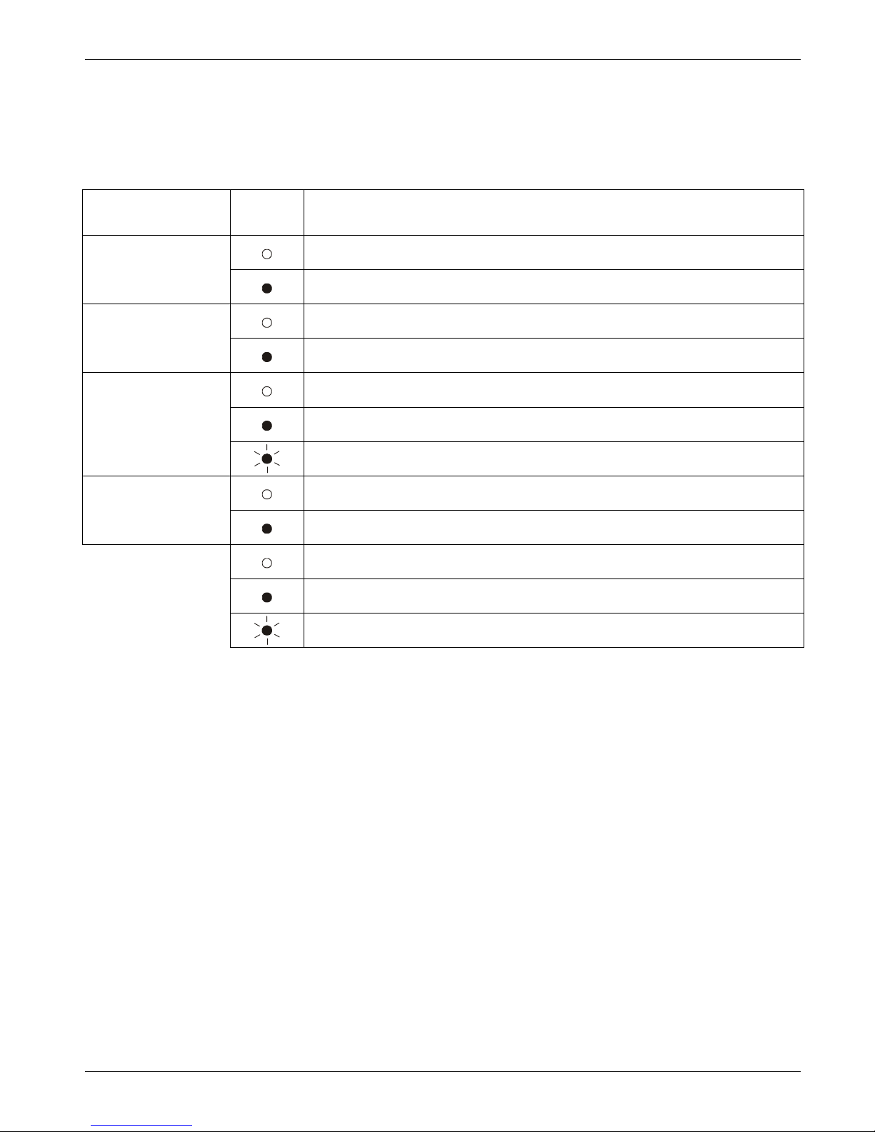
9 Led status and Alarms
9.1 LED Status Table
In front of the thyristor unit there are LED that indicates the state of the Electronic cards:
LED
For All size
STATUS DESCRIPTION
The power supply is not connected or fault on the electronic board
Aux
The power supply is not connected and the Electronic board is OK
OFF Condition (Load IS NOT Powered)
ON
ON Condition (Load IS Powered)
SCR OK
SCR short circuit
SC
No External Enable (see par. 11.4)
Load OK
HB
Load Fault
= OFF
= ON
= Flashing
9.2 Not Critical Alarm
The Not Critical Alarm, doesn’t stop the thyristor unit.
When one of these Not Critical Alarm is active, the HB relay change status (see par. 11.5)
9.2.1 SCR Short Circuit (only with the HB option)
This alarm is active when the thyristor unit read the output current in absence of the input signal. This is
possible if there are a short circuit on the thyristor or if there are a wrong wiring of the load.
When the problem is solved is necessary use the digital input: “Reset”
(Terminals 3-4)
Page 24
CD Automation srl CD3200-1PH from 15A to 110A User’s Manual
24
9.2.2 Heater Break alarm HB (only with the HB option)
This alarm is active when the load current decrease under the threshold set on the parameter P126H
(see par. 13).
The Heater Break alarm could be active also if there are a wrong wiring of the load.
When the problem is solved is necessary use the digital input: “Reset”
(Terminals 3-4).
The Heater Break circuit to work properly must have at least an input of 25% of the nominal current.
H.B. circuit read load current via a current transformer 25-50/0.05 or 100/0.05 depending on thyristor
size.
Minimum current is 30% of the current transformer size’s. If load current is below this value make two
turns or more around current transformer. H.B. circuit also diagnoses fuse failure.
Caution: In the first start, and each time that the load is replaced, it’s necessary make the
Calibration procedure
.
9.3 Calibration Procedure
The Calibration procedure is an automatic procedure that save in memory the value of load current.
To make the Calibration procedure follow these steps:
• Turned completely in counter-clockwise sense the trimmer R13 (see par 10.3 )
• Give the power supply
• Press the “CAL” button on front unit, or use the configurable digital input (see par. 11.4).
• All LEDS are on, this means that calibration procedure is active.
• Turn the trimmer R13 in clockwise sense and set the wished current limit.
• After a minute the values of voltage and current are stored in memory.
• the CD3200 comes back to the initial situation.
The Calibration procedure is done.
10 Firing type
Choose an correct firing type allows to optimize the thyristor unit for the installed load.
The firing type has already configured in line with customer requirements that are defined in the Order
Code. The Order Code is written on the identification label.
However, if you wish to change the firing type you can use the software configurator or the parameter
on serial link (see par. 13).
Caution: this procedure must be performed only by qualified persons.
Page 25
CD Automation srl CD3200-1PH from 15A to 110A User’s Manual
25
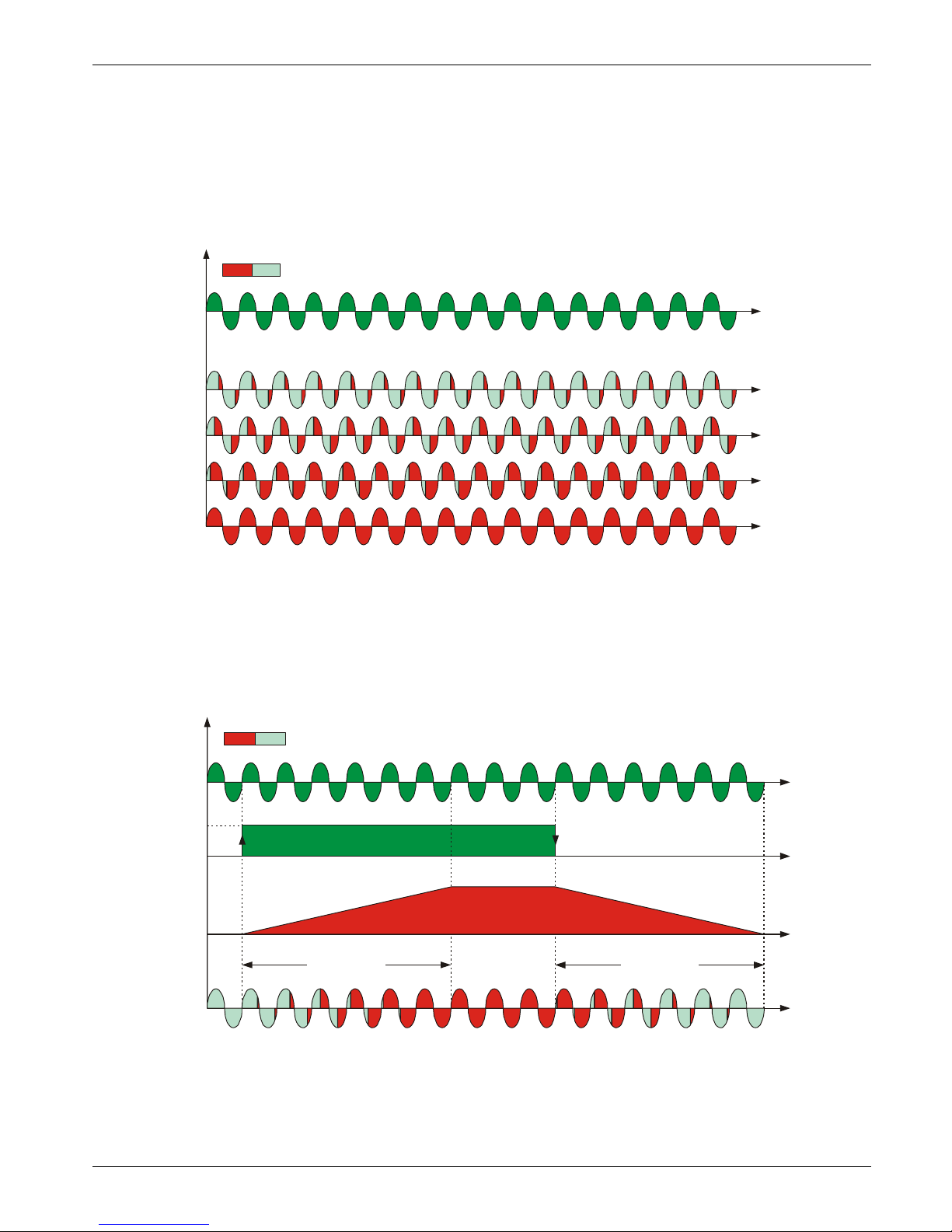
10.1 Phase Angle (PA)
The Phase Angle firing allow the control of the power on the load, for this firing the thyristor can be in
conduction only for a part of the voltage cycle.
This part of the voltage cycle is adjustable in function of the input signal from 0 at 100%.
The PA firing is normally used for control the inductive loads, and is also possible control a primary of
transformer coupled with the cold resistances like: Superkanthal, Molybdenum, Platinum, Tungsten or
Quartz Lamp. The only disadvantage with phase angle is the possible generation of interferences that
however can be reduced with opportune filters.
VOLTAGE SUPPLY (V)
100%
ON OFF
LOAD VOLTAGE (V)
75%
50%
25%
10.2 Soft Start with Phase Angle (S+PA)
This is an additional function to the Phase Angle. The firing angle of the thyristor increase or decrease up
to the final setpoint value.
The Soft start ramp is an important feature to reduce the inrush current with transformers during the
during the cycle of magnetization or with cold resistance that are near to the short circuit when they are
supplied.
VOLTAGE SUPPLY (V)
ON OFF
Setpoint Value (%)
OUTPUT VOLTAGE (V)
100%
0%
Ramp Up Ramp Down
Load voltage RMS (V)
Page 26
CD Automation srl CD3200-1PH from 15A to 110A User’s Manual
26
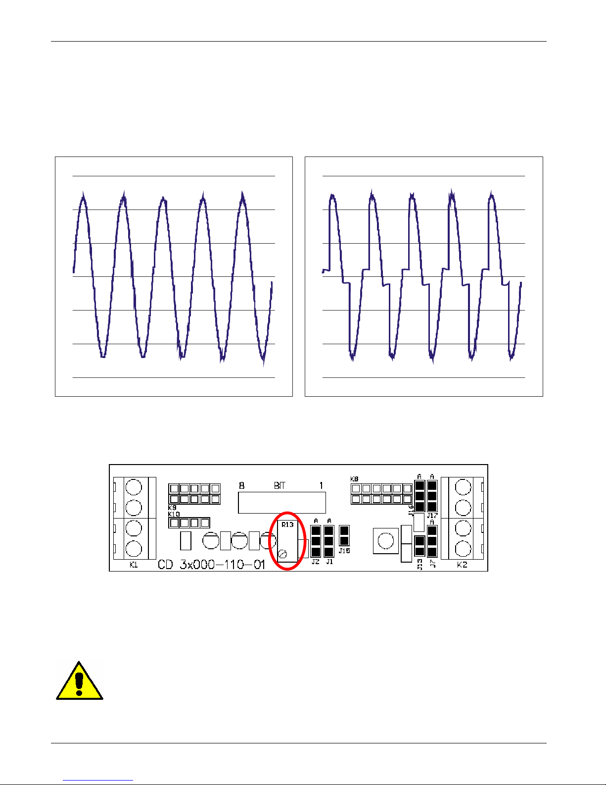
10.3 Action of the Limit Current
The Current Limit control the firing angle of the thyristor to maintain the RMS current under the set
value.
When the current exceeds this value, the voltage is decreased up to reach the current limit set
I Load <= I Limit Set I Load > I Limit Set
10.3.1 Current Limit Set
The Current limit is set up through the R13 trimmer on Frontal Board PCB (see par. 11.1)
Turned completely in counter-clockwise sense, will be Current limit = 0%.
Turned completely in clockwise sense, will be Current limit = 100% of the Max value of current
transformer (25/0.05 ,50/0.05 o 100/0.05 depending on thyristor size).
Minimum current is 25% of the current transformer size’s. If load current is below this value make two
turns or more around current transformer. H.B. circuit also diagnoses fuse failure.
If the External current limit profiling is used, before turning the R13 trimmer, supplying with 10Vdc the
secondary analogic input (see par. 11.3.3)..
Caution: this procedure must be performed only by qualified persons
Page 27

CD Automation srl CD3200-1PH from 15A to 110A User’s Manual
27
10.4 Feed-back type
The Feed-back type has already configured in line with customer requirements that are defined in the
Order Code. The Order Code is written on the identification label.
However, if you wish to change the Feed-back type you can use the software configurator or the
parameter on serial link (see par. 13).
Caution: this procedure must be performed only by qualified persons..
If the configurable digital input has set like Feed-Back Selection (see par. 11.4), it's possible to change
the select Feed-Back with the Voltage Feed-Back (V) simply activating the input.
The feed-back defines the Control Mode. It’s possible to have:
• V=Voltage feed-back.
The input signal is proportional to the output voltage. This means that input signal becomes a
voltage demand. This control mode compensates the voltage fluctuation of the incoming line supply.
• I=Current feed-back.
The input signal is proportional to the current output. This means that input signal becomes a
current demand. This control mode maintain the current also if the load impedance changes.
• V2=Square Voltage feed-back.
The input signal is proportional to the output square voltage. This means that input signal becomes
a power demand. The power remains constant if the load impedance doesn't change.
• VxI= Power feed-back.
The input signal is proportional to the power output. This means that input signal becomes a power
demand. The power remains constant also if voltage and load impedance change. This feed-back is
used with silicon carbide elements that change its resistive value with temperature and with age. In
addition it compensate the voltage fluctuation of the incoming line supply.
If the user change the type of feed-back, it’s necessary repeat the calibration procedure
(see par. 9.3)
Page 28
CD Automation srl CD3200-1PH from 15A to 110A User’s Manual
28
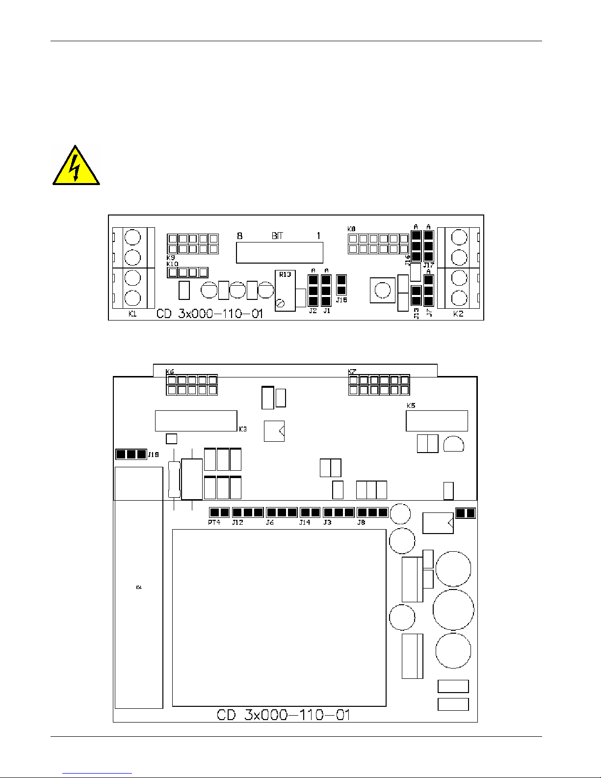
11 Connection description
11.1 Access to the Electronic boards
To have access to the electronic boards the user must removing the unit’s cover
(see par.7.1)
Warning: Before operate, be sure that power and control cables are isolated from voltage
sources
Front PCB
Main PCB
Page 29
CD Automation srl CD3200-1PH from 15A to 110A User’s Manual
29
11.2 Supply the Electronic Board
The CD3200 thyristor unit, to work, requires a voltage supply for the electronic boards. The Max
consumption is 10VA.
The voltage supply for the electronic boards is configured in line with customer requirements that are
defined in the Order Code. The Order Code is written on the identification label.
Warning: Before connecting or disconnecting the unit check that power and control cables
are isolated from voltage sources.
Terminal Description
16 Voltage Supply for Electronic Boards (Auxiliary Voltage)
17 Earth
18 Voltage Supply for Electronic Boards (Auxiliary Voltage)
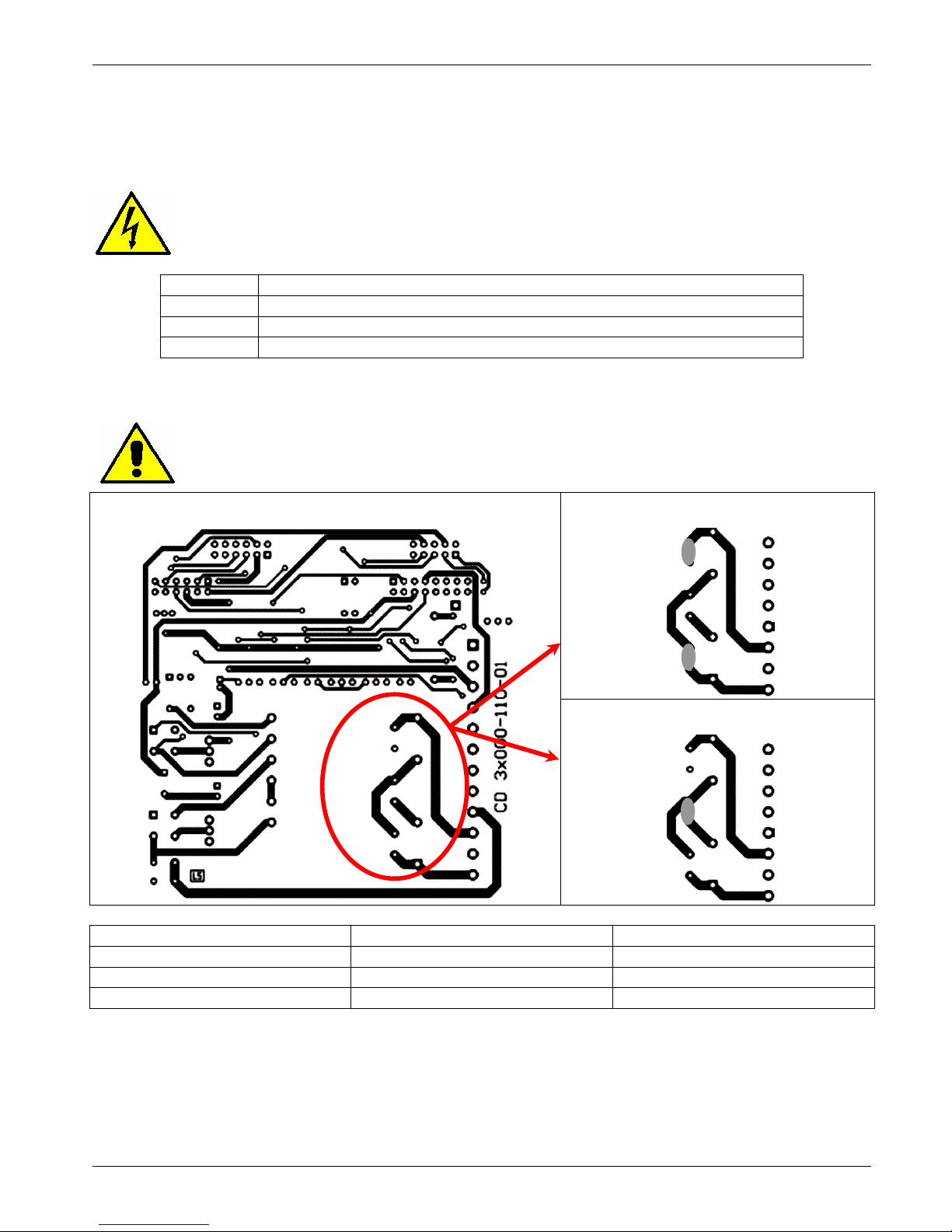
To change auxiliary supply voltage sold the correct link-jumper on main PCB:
Warning: this procedure can be done just by specialized personnel.
Link-Jumper J9+J11
Main PCB
Link-Jumper J9+J11
Transformer Type Link-Jumper J9+J11 Link-Jumper J10
TR-605 120V 90:130V TR-605 230V 170:265V 300:530V
TR-605 300V 230:345V 510:690V
• The type of mounted transformer depends of the chosen Auxiliary Voltage in the order code.
(see par. 5.2)
• If the Auxiliary Voltage (written on the identification label) is different from Supply Voltage (to the
load), use an external transformer with primary equal to load voltage and secondary equal to the
Auxiliary Voltage.
J9
J10
J11
J9
J10
J11
J9
J10
J11
Page 30
CD Automation srl CD3200-1PH from 15A to 110A User’s Manual
30
11.3 Analog Inputs
CD3200 thyristor unit have have an analogue input to drive the output and a second analogue input that
can be use for external current profiling
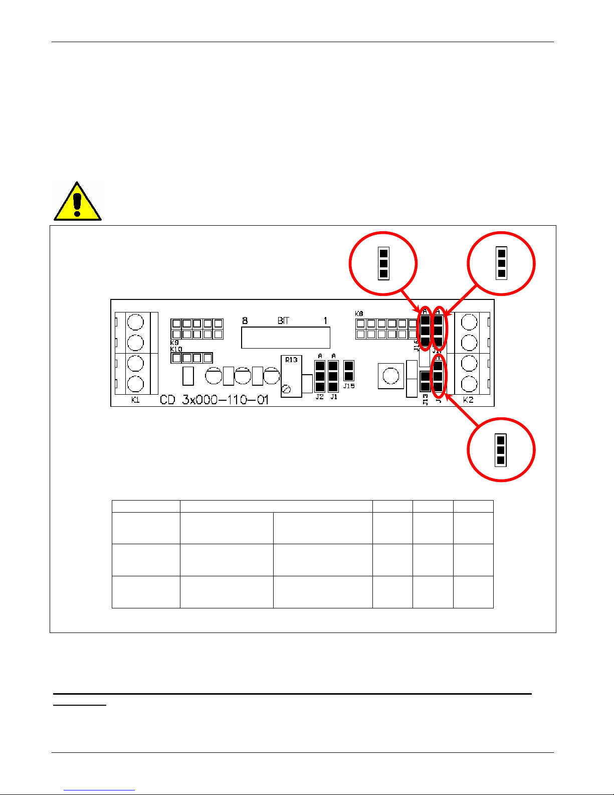
11.3.1 Input command signal configuration (Terminals A2+ and A1- see par. 7.4)
The Input command signal is already configured in line with customer requirements that are defined in
the complete product code. The product code is written on the identification label.
However, if you wish to change the input type (i.e. from 0÷10V to 4÷20mA) proceed as follows:
Warning: this procedure can be done just by specialized personnel
Front PCB
J1
6
A
B
C
J1
7
A
B
C
To configure the input type, set the jumper as below represented:
J7
A
B
C
Type Input features J7 J16 J17
0÷10V Impedance 10KΩ C-B B-A B-A
POT Impedance 10KΩ min C-B B-A B-A
4÷20mA Impedance 100Ω B-A B-A B-A
When operator finishes to configure the hardware setting he must do the input calibration
procedure
Page 31
CD Automation srl CD3200-1PH from 15A to 110A User’s Manual
31
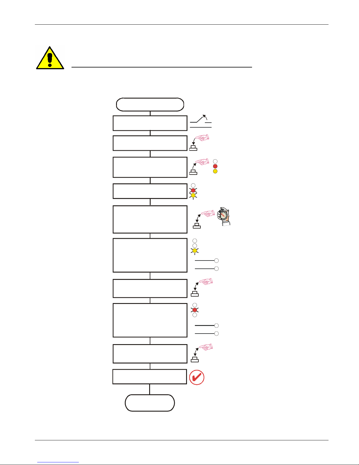
11.3.2 Input calibration procedure
Warning: this procedure can be done just by specialized personnel
This procedure is needed only if you change the input type
Auxiliary power supply
OFF
Start TUNE
End
TUNE
Mantain Key CAL pushed
and give the power supply
Analog input
is tuned
Within 10 sec. from start
flashing yellow and red leds
push again momentary
CAL Key
Yellow led only is
flashing, apply
0 input Signal
I.E.: 0V for 0-10V
4mA for 4-20mA
Now press CAL Key again
Release key
when red and yellow
led are ON
Yellow and Red leds
are flashing
ON
ON
2sec.
S/C
S/C
H.B.
H.B.
ON
S/C
H.B
ON
S/C
H.B
0% Signal
100% Signal
Red led only is
flashing, apply
10V for 0-10V input
or
20mA for 4-20mA input
Now press CAL Key again
Page 32
CD Automation srl CD3200-1PH from 15A to 110A User’s Manual
32
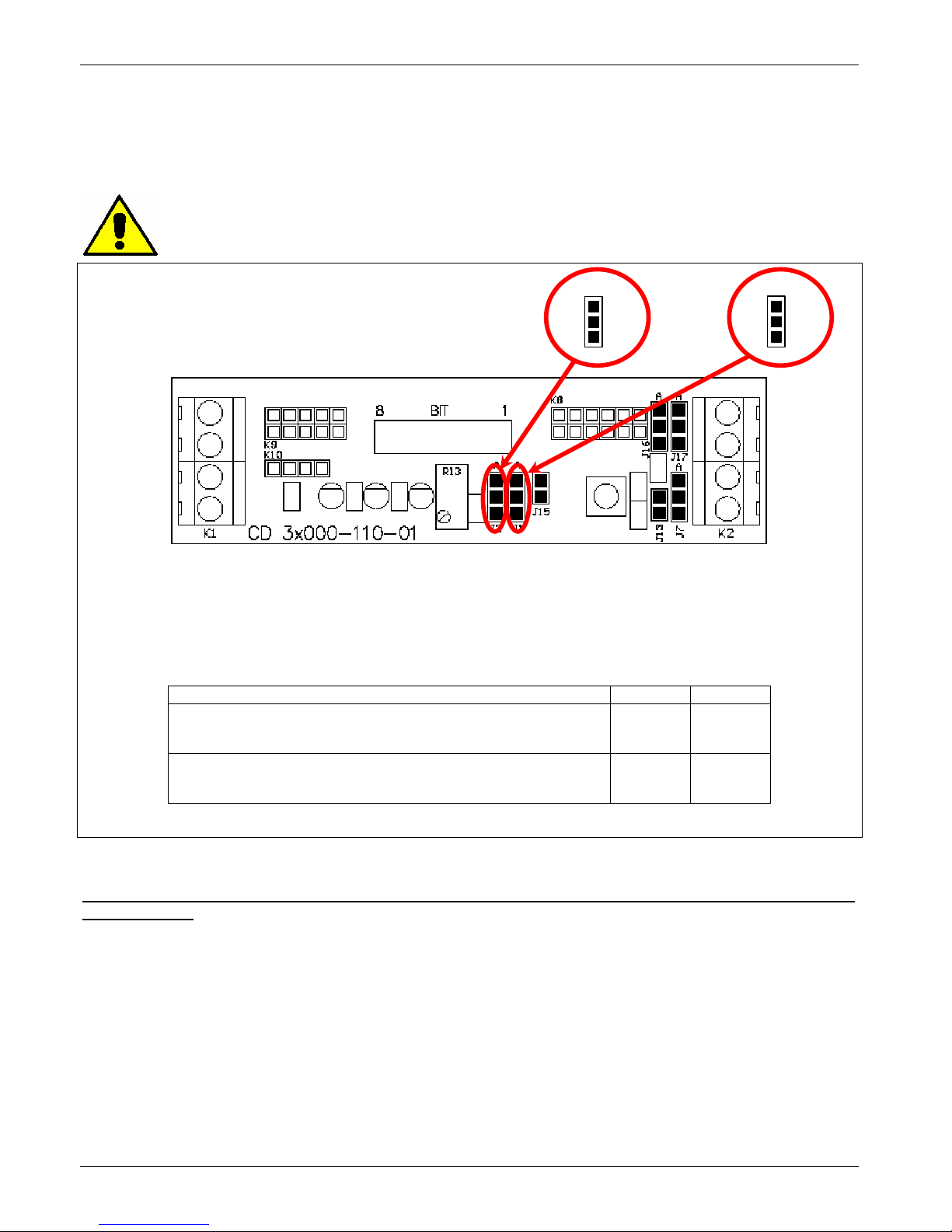
11.3.3 Secondary input (Terminals 12 & A1- see par. 7.4)
This analogue input 0-10V may be configured for External current limit profiling.
The Secondary input is already configured in line with customer requirements that are defined in the
complete product code. The product code is written on the identification label.
However, if you wish to change the input type proceed as follows:
Warning: this procedure can be done just by specialized personnel
Front PCB
J2
A
B
C
J1
A
B
C
To configure the input type, set the jumper as below represented:
Current Limit J2 J1
Regulation through the R13 trimmer, mounted on the
front PCB. (secondary input not used)
C-B C-B
Regulation through the secondary input
(External current limit profiling)
B-A C-B
If the user change the type of Secondary input, it’s necessary repeat the calibration procedure
(see par. 9.3)
11.4 Digital Input
CD3200 thyristor unit has two digital inputs.
Page 33
CD Automation srl CD3200-1PH from 15A to 110A User’s Manual
33
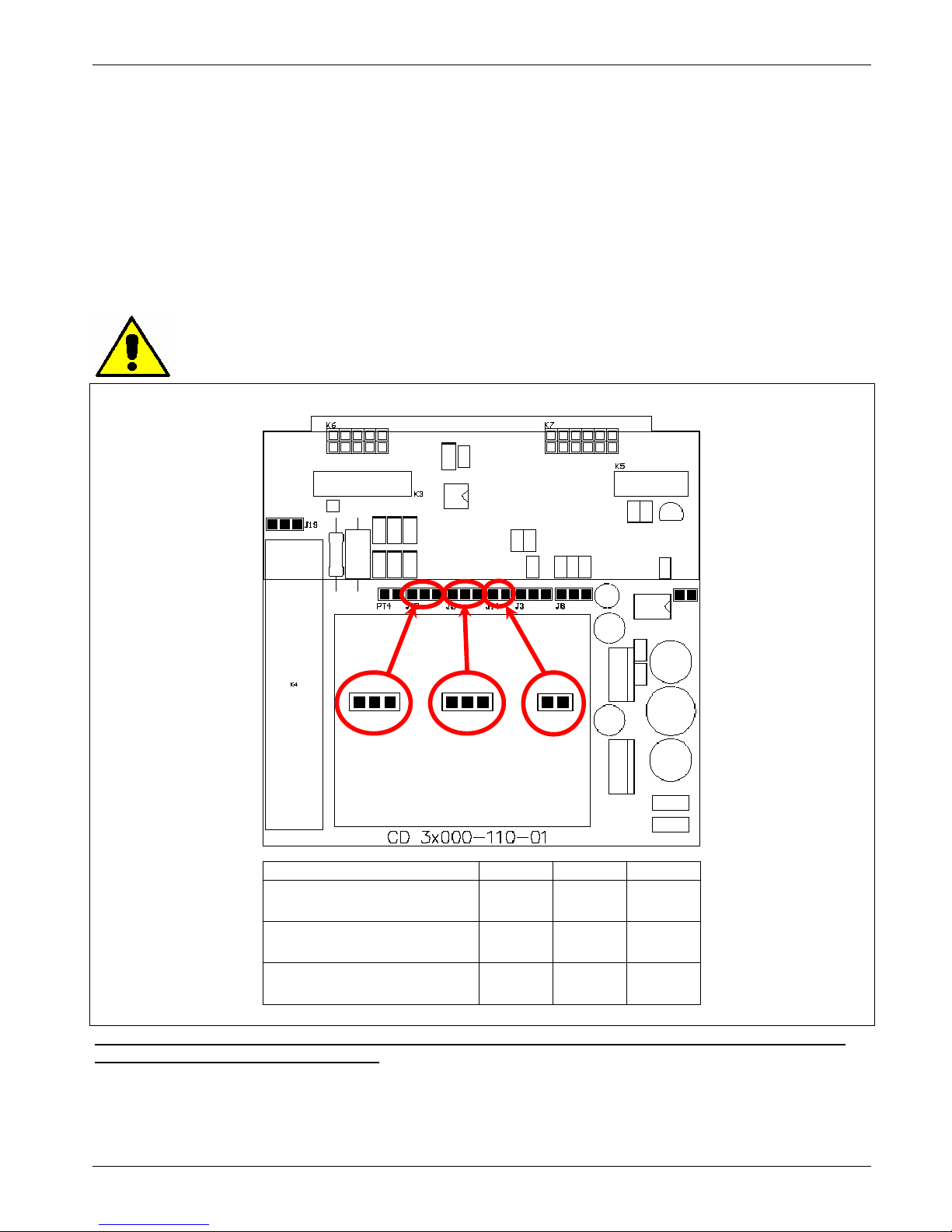
11.4.1 Configurable Input (Terminals 1 and 2 see par. 7.4)
This digital input is configurable and can be:
• External Calibration (Standard):
The Calibration input activates the Calibration procedure that is necessary if you use the Heater
break alarm (see par. 9.3). Supply with 24Vdc terminals 1-2 to start the Heater Break procedure.
• External Enable:
Without Enable the out is always to zero and red led (SC) flashing, otherwise the out will follow the
input signal.
• Feed-back Selection:
to switch the set Feed-back with the voltage Feed-back (V)
Without Digital Input the Unit use the voltage Feed-back, otherwise use the set Feed-back.
To configure the input type, set the jumper as below represented:
Warning: this procedure can be done just by specialized personnel
Main PCB
Type J12 J6 J14
External Calibration C-B C-B Open
External Enable B-A Open Open
Feed-back Selection * C-B Open Close
* With the Feed-back Selection open the jumper J15 on the Front PCB board
If you use the input like External Enable or like Feed-back Selection, is not possible use the
input for the Calibration Procedure
11.4.2 Reset (Terminals 3 and 4 see par. 7.4)
The Reset Alarm is used for restore the unit after an alarm occurs (see par. 9.2).
Open link to terminals 3-4 to stop the CD3200 thyristor unit and reset the alarm.
J12
C B A
J6
C B A
J14
Page 34
CD Automation srl CD3200-1PH from 15A to 110A User’s Manual
34
11.5 Digital Output
CD3200 thyristor unit with HB option has 1 digital output with relay contact (Max 500mA, 125Vac) that
gives indications of the alarms state, the contacts can be (NO or NC).
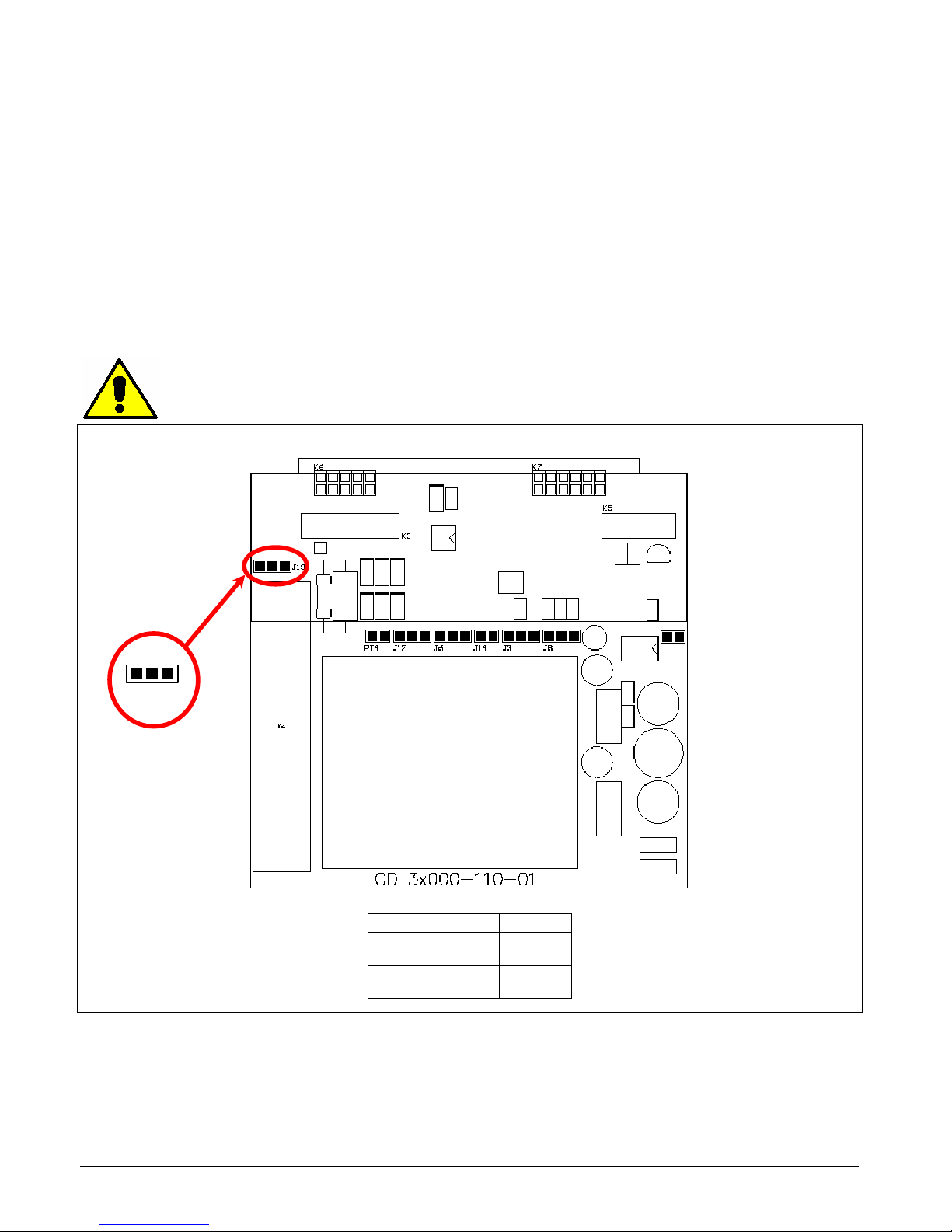
11.5.1 HB alarm contact (Only with HB Option - see par. 9.2)
The standard contact used for this output is normally open (NO):
• In normal conditions (without alarm) and with auxiliary power supply, the contact to the terminals
has opened (relay coil energized).
• In alarm condition or without auxiliary power supply the contact to the terminals is closed
(relay coil not energized).
if you wish to change the alarm contact put the jumper as shown:
Caution: this procedure must be performed only by qualified persons
Main PCB
J19
C B A
Type J19
NO (standard) C-B
NC B-A
Page 35
CD Automation srl CD3200-1PH from 15A to 110A User’s Manual
35
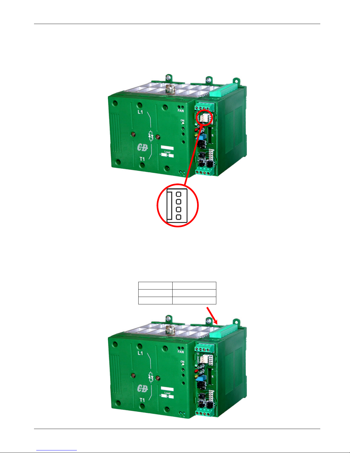
11.6 PG Connector
The PG Connector is used to configure the thyristor unit with the configuration software and with the
programming cable.
The programming cable is not included.
PG Connector
11.7 RS485 Serial Port
The serial communication port is on Terminals 7 and 8.
On this port may be done a network up to 255 unit.
Terminal Description
7 RS485 A
8 RS485 B
Page 36
CD Automation srl CD3200-1PH from 15A to 110A User’s Manual
36
11.8 Address configuration
The thyristor unit is assigned a unique device address by the user in the range 1 (default) to
255. This address is used to recognise the messages queries to her assigned.
The thyristor unit does not respond at the messages queries that don't have the same assigned address.
The thyristor unit will also accept global messages (Broadcast) sends at the address 0. No responses are
returned for globally addressed queries.
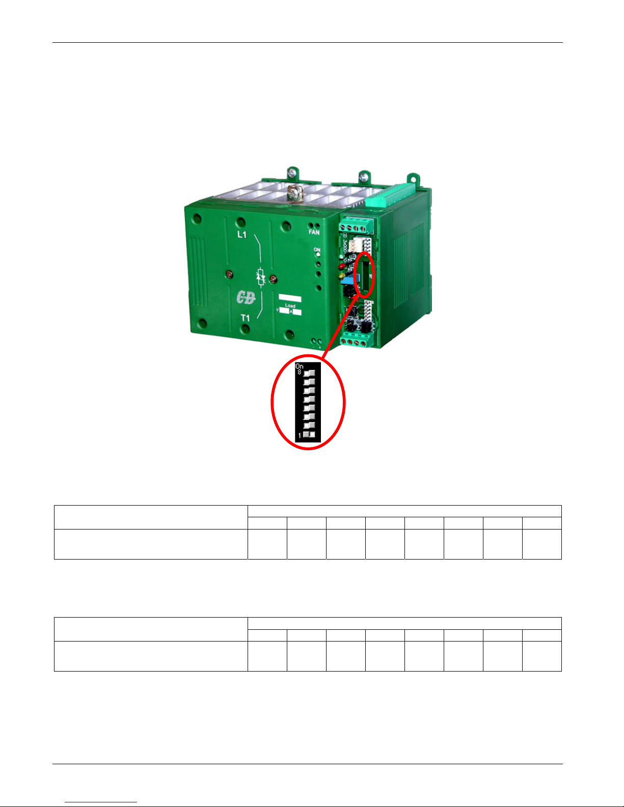
To configure communication address remove cover and set the dip-switch as below specified:
Dip Switch
Convert the Address Number in Binary for Example: 150 Dec = 10010110 Bin
The dip switch number corresponds to the bit number:
Dip Switch Number
Address Number
8 7 6 5 4 3 2 1
150 Dec -> 10010110 Bin
1
(On) 0 (Off) 0 (Off) 1 (On) 0 (Off) 1 (On) 1 (On) 0 (Off)
For convert the Number in Binary you can use this method:
Dip Switch Number have this value:
Dip Switch Number
8 7 6 5 4 3 2 1
Value 128 64 32 16 8 4 2 1
The Address Number Ex. 150 = 128(Dip 8) + 16(Dip 5) + 4(Dip 3) + 2(Dip2)
Page 37
CD Automation srl CD3200-1PH from 15A to 110A User’s Manual
37
12 MODBUS communication
The serial communication port of the thyristor unit is two-wire RS485 type.
This port use an half-duplex system.
When a Unit must transmit active the transmission line, and when there are not units in transmission
the outputs are fixed to high impedance.
The serial communication port allows to communicate between the thyristor units and a MASTER device
(ex. an computer or a terminal). The cable must be rated for use to data transfer.
12.1 MODBUS RTU Protocol
The communication is based on the standard industrial MODBUS RTU with the following restrictions:
• The Baud rate is 9600 Baud.
• The Preset Multiple Registers (Funct. 16) is limited to the writing of a single parameter
for message.
The following MODBUS functions are supported:
Function Description
03 Read Holding Registers
16 Preset Multiple Registers
The unit support the Broadcast messages:
It' possible send a Broadcast messages using the address 0, all the units respond at the
message without sending back any reply.
12.2 Message Format
The transmission format is a 1 bit start, 8 date bit, and 1 bit stop with no parity verification.
Each message terminate after a said time of "time out", equal at 3.5 time of a character transmission,
where there are not transitions on the transmission line.
The first Byte of each message is always the address of the unit that is a value from 1 to 255 or 0 for the
broadcast messages, the second is always the function number, and the rest of the message depends of
the function demand.
When a Slave receive an message, the unit send an answer with the same structure but
with the information demanded.
Each message is followed by CRC (Cyclic Redundancy Check) with two byte. The CRC identify the
incongruity situations of the message, in this case the receiver ignore the message.
The CRC is calculated in accordance with a formula that imply a recursive division of the data by a
polynomial.
The polynomial divisor is:
2
16
+ 215 + 22 + 1(Hex 18005)
but is modified in two ways:
• Since the bits order are reversed, then the binary pattern is also reversed, and the most significant
bit (MSB) is the right-most bit.
• Since interest only the remainder, the right-most bit could be discarded.
Therefore, the polynomial divisor has value: Hex A001
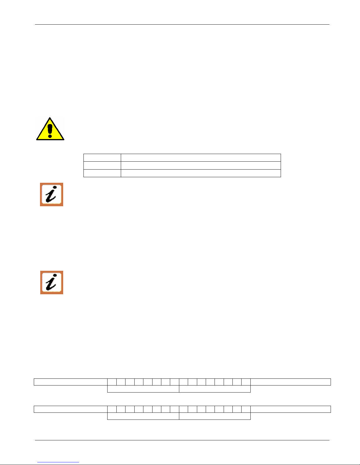
Normal bit order:
Most significant bit Least significant bit
Most significant Byte Least significant Byte
Reversed bit order:
Least significant bit Most significant bit
Least significant Byte Most significant Byte
N.B.: With the reversed bit order, also the CRC16 returns the with the reversed bit order
Page 38
CD Automation srl CD3200-1PH from 15A to 110A User’s Manual
38
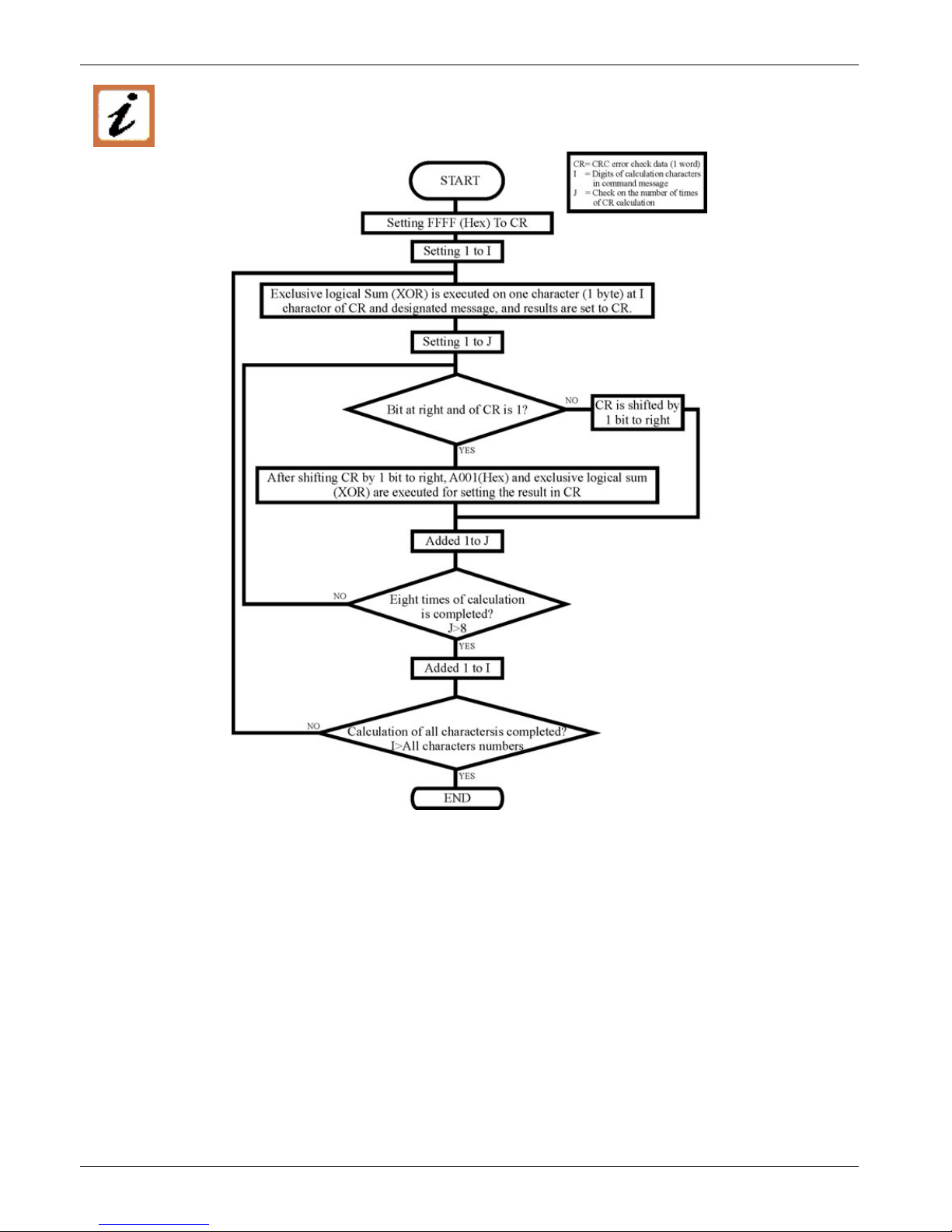
The following flow-diagram show how to organize the CRC 16 bit.
C Language CRC 16 Example
static short CRC16 (unsigned char *p_first,unsigned char *p_last)
{
unsigned int crc=0xffff;
short j;
for (;p_first<=p_last;p_first++)
{
crc ^= *p_first;
for(j=8;j>0;j--)
{
if(crc & 0x0001)
{
crc = crc >> 1;
crc ^= 0xA001;
}
else
{
crc = crc >> 1;
}
}
}
return (crc);
}
Page 39
CD Automation srl CD3200-1PH from 15A to 110A User’s Manual
39
12.3 Read Holding Registers
This function reads the instantaneous value of a specified number of parameters from an address.
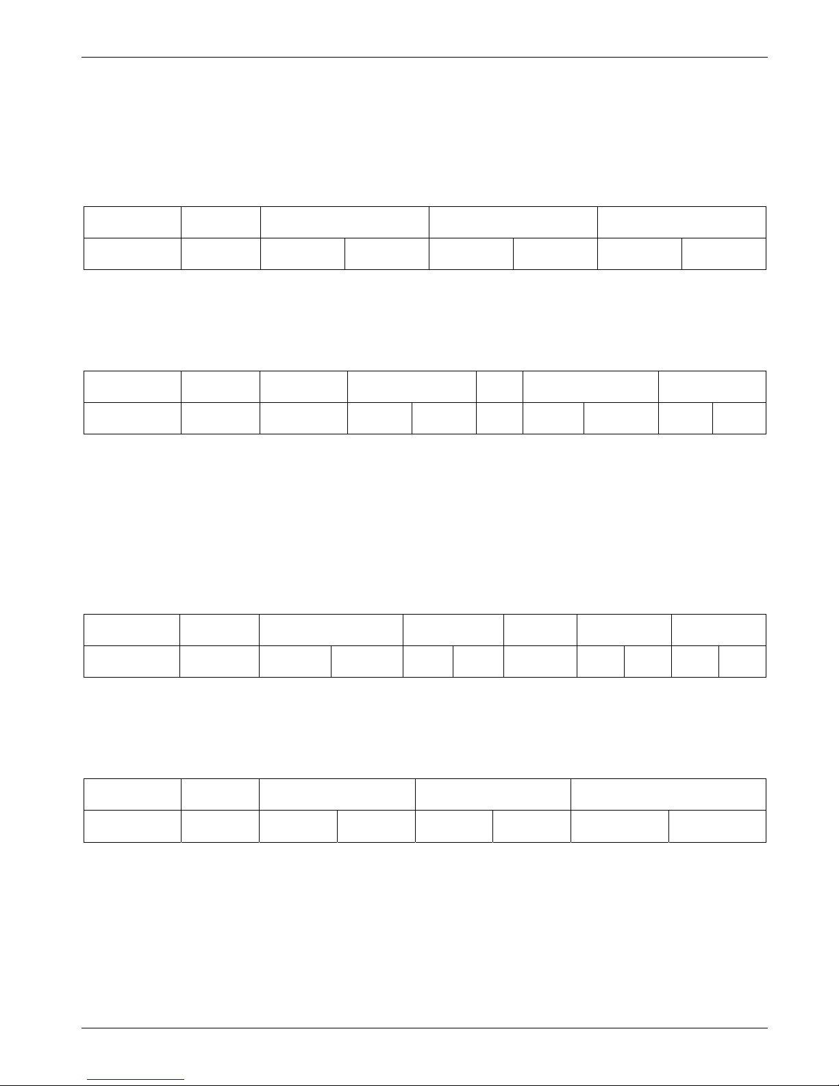
The message is composed by 8 Byte: one Byte is for the address, one for the function (03 Hex), two
Byte for the first parameter to read, two Byte for the total number of parameters to read and finally two
Byte for the CRC:
Address
Unit
Function
Address of the First
Parameter
N° of the Parameter CRC 16
3
3Hex
HI LO HI LO LO HI
The answer is an echo of the first two Byte (address and function), one byte with the number of
following byte to exclusion of the CRC, the demanded values and finally two Byte for the CRC:
Address
Unit
Function N° of Byte
First Parameter
Value
Last parameter
value
CRC 16
3
3Hex
HI LO … HI LO LO HI
12.4 Preset Multiple Registers
This function could write only a parameter for each message.
The message is composed by 11 Byte: one Byte for the address, one for the function (10 Hex), two Byte
for first parameter to write, two Bytes for the N° of parameters, fixed to 1 (0001 Hex), one Byte with the
number of following Bytes, fixed to 2 (02 Hex), two Byte for the CRC:
Address
Unit
Function
Address of the
First Parameter
N° of the
Parameter
N° of
Byte
Value to
write
CRC 16
16
10Hex
HI LO 0 1 2 HI LO LO HI
The answer is an echo of the first two Byte (address and function), two Byte for first written parameter,
two Byte with the N° of parameters, fixed to 1 (0001 Hex), two Byte for the CRC:
Address
Unit
Function
Address of the First
Parameter
N° of the
Parameter
CRC 16
16
10Hex
HI LO 0 1 LO HI
Page 40
CD Automation srl CD3200-1PH from 15A to 110A User’s Manual
40
12.5 Error and exception responses
If a message contains an altered character, if fails the CRC, or if the received message contains a syntax
error (for example the number of the byte or of the words is not correct), then the unit will ignore the
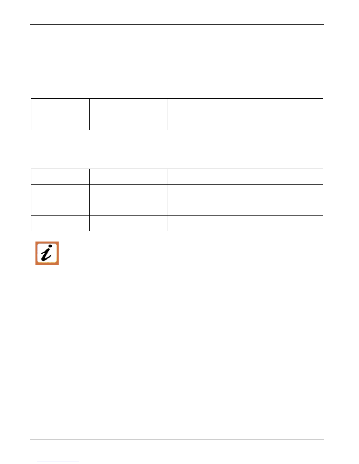
message.
If the received message is correct but contains a not valid value, the unit will send an answer of
exception (5 byte):
Address Unit Function Error Code CRC 16
LO HI
The byte with the function number, represent the function number of the message that has caused the
error with the first Bit set to 1 (ex. the function 3 becomes 0x83) The error code could be one of the
followings:
Error Code Name Cause
1 ILLEGAL FUNCTION Function not supported.
2 ILLEGAL DATA ADDRESS Address out of range.
3 ILLEGAL DATA VALUE Attempt to write invalid or action not carried out.
NOTE: If you write a parameter's value equal at his actual value this is a valid transaction
and don't cause an error.
Page 41

CD Automation srl CD3200-1PH from 15A to 110A User’s Manual
41
13 Configuration Parameters
The Configuration Parameters are accessible from the software configurator or through the serial
communication port RS485.
P001L (H01) Byte Lo = Load Voltage R
Function: This parameter show the Voltage rms value
Min/Max: 0 ÷ 255 (0 ÷ FF Hex)
Value: Value depends on the Unit type
P001H (H01) Byte Hi = Load Current R
Function: This parameter shows the Current rms value.
Min/Max: 0 ÷ 255 (0 ÷ FF Hex)
Value: Value depends on when turns have current transformer and from his size’s.
Example: With one passage on the current transformer (CT) 25/0.05A, the max value
corresponds to the max value of the CT:
Read value=255 (FF Hex) -> Load Current= 25A
P002L (H02) Byte Lo = Set-point Voltage R/W
Function: This parameter is the Set-point voltage saved by the Calibration Procedure
Min/Max: 0 ÷ 255 (0 ÷ FF Hex)
P002H (H02) Byte Hi = Set-point Current R/W
Function: This parameter is the Set-point of current below which HB alarm occurs
Min/Max: 0 ÷ 255 (0 ÷ FF Hex)
Value: This value is the load current(P001H) minus % value of parameter P126H
P003 (H03) Status Table R
Function: It’s a tab in bit that represent the “Status” of thyristor unit
Value: Bit 0 = 1 -> Short circuit on SCR
Bit 1 = 1 -> Load Failure (HB Alarm)
Bit 2 = 1 -> Output signal ON
Bit 3 = 1 -> HB Calibration in progress
Bit 4 = 1 -> Current Limit Flag
Bit 5 = 1 -> Thermal switch
P004 (H04) Command Table R/W
Function: It’s a tab in bit for remote commands via RS485
Value: Bit 0 = 1 -> Activate HB Calibration procedure
Bit 1 = 1 -> Input Command from RS485 (see P005)
Bit 2 = 1 -> Disable Output signal (Only with Input from RS485)
Bit 3 = 1 -> Reset HB Alarm
Bit 4 = 1 -> Current Limit via RS485 (see P007)
Note: When unit is switch off all command parameter are set to 0
P005L (H05) Input command signal R
Function:
This parameter reads the Input command signal (see par. 7.4)
When the P004 Bit1 =1 This parameter could be written and become the Input
Command from RS485
Min/Max: 0 ÷ 255 (0 ÷ FF Hex)
Example: Input 4mA -> P005L = 0 (0%)
Input 12mA -> P005L = 128 (50%)
Input 20mA -> P005L = 255 (100%)
P005H (H05) Byte Hi = Ramped Input command signal R
Function: This parameter reads the Input command signal after the ramp
Min/Max: 0 ÷ 255 (0 ÷ FF Hex)
Example: Input 4mA -> P005H = 0 (0%)
Input 12mA -> P005H = 128 (50%)
Input 20mA -> P005H = 255 (100%)
Page 42
CD Automation srl CD3200-1PH from 15A to 110A User’s Manual
42
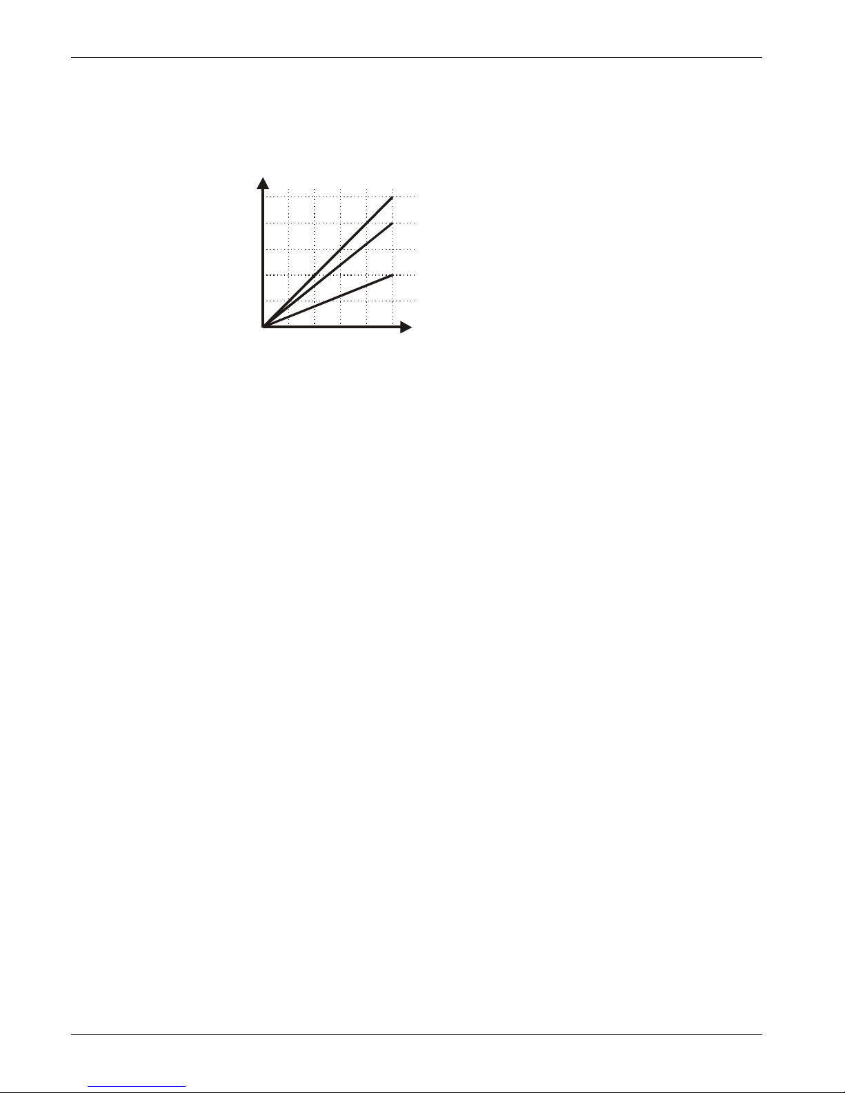
P006 (H06) Power adjust R/W
Function: Its’ a scaling factor of the Input command signal
Min/Max: 0 ÷ 255 (0 ÷FF Hex)
Value: from 0 = 0% of Output,
To 255 = 100% of Output.
Note: This parameter limit the Output Power
100
Power Adjust = 100%
Power Adju st = 80%
Power Adju st = 40%
80
60
40
20
0
4020 60 10080
Input %
OUT %
P007 (H07) Current Limit R
Function: This parameter show the Current Limit value (see par. 10.3)
When the P004 Bit4 =1 This parameter could be written and become the
Current Limit from RS485
Min/Max: 0 ÷ 255 (0 ÷ FF Hex)
Value: Value depends on when turns have current transformer and from his size’s
Example: With one passage on the current transformer (CT) 25/0.05A, the max value
corresponds to the max value of the CT:
Read value=255 (FF Hex) -> Load Current= 25A
P121 (H79) CD Unit ID R
Function: This parameter Identify the CD type Family
Value: CD32 Hex = CD3200 Family
P122 (H7A) CD Ver R
Function: This parameter is for internal use
P123 (H7B) Password R/W
Function: This parameter give the access to configuration
Min/Max: 0 ÷ FFFF Hex
Value: 9357 Hex = Writing parameters activated
any value = Writing parameters disabled
Note: When the unit comes out and then re-lighted, for change the parameters you
must re-insert the password.
P124 (H7C) Actual power R
Function: This parameter show the actual value of the power demand
Min/Max: 0 ÷ 65535 (0 ÷ FFFF Hex)
Value: from 0 = 0% output power,
to 65535 = 100% output power.
Page 43

CD Automation srl CD3200-1PH from 15A to 110A User’s Manual
43
P125L (H7D) Byte Lo = Feed-Back Type R/W
Function: This parameter set the Feed-Back Type
Value: 00 Hex = V2
20 Hex = V
40 Hex = I
80 Hex = VxI
Default: 20 (if not specified in the Order Code)
P125H (H7D) Byte Hi = Soft start time R/W
Function: The Unit starts in phase angle mode with a ramp starting from zero up to full
voltage in a presetted and Adjustable time.
The time is setted by this parameter
Min/Max: 0 ÷ 255 (0 ÷FF Hex)
Value: Each step is 50msec
Default: 20 (S+PA)
P126L (H7E) Byte Lo = HB Delay time R/W
Function: This parameter set a delay to have HB alarm active
Min/Max: 1 ÷ 255 (0 ÷ FF Hex)
Value: Each step is 50msec
Default: 30 (if not specified in the Order Code)
Note: If Soft start option is enabled HB Delay time must be greater than Soft start
time: P126L x 50msec > P125H x 50msec
P126H (H7E) Byte Hi = HB sensibility R/W
Function: This parameter is the maximum reduction of Load Current to establish the HB
Alarm
Min/Max: 0 ÷ 100 (0 ÷64 Hex)
Value: Each step is 1% from Nominal Current
Default: 14 Hex
Note: When you change this parameter, HB Calibration procedure is necessary.
P127 (H7F) Power Set R/W
Function: This parameter show the Power set saved by the Calibration Procedure
Min/Max: 0 ÷ 65535 (0 ÷ FFFF Hex)
Value: from 0 = 0% output power,
to 65535 = 100% output power.
P128L (H80) Byte Lo = Integral R/W
Function: This parameter is the integral time of the feed-back loop
Min/Max: 0 ÷ 255 (0 ÷FF Hex)
Default: 50 Hex
Note: If you increase integral time you increase the output stability, but you increase
also the time to reach the set.
P128H (H80) Byte Hi = Proportional R/W
Function: This parameter is the gain of the feed-back loop
Min/Max: 0 ÷ 255 (0 ÷FF Hex)
Default: VxI or V2 = 5 Hex
V or I =12 Hex
Note: This parameter increase the loop speed but decrease the loop stability.
Page 44
CD Automation srl CD3200-1PH from 15A to 110A User’s Manual
44
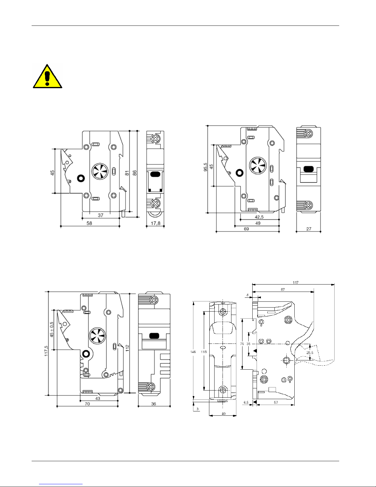
14 FuseHolder and Fuses
CD3200 unit must be protected by fuses against short circuit selecting the proper I²t that must be lower
than the thyristor one (I²t max).
Caution:
USE ONLY EXTRARAPID FUSE WITH APPROPRIATE I²T
14.1 FuseHolder size
for size 15A - 25A for size 35A - 45A
for size 60A - 90A(CE) for size 90A(UL) - 110A
Page 45
CD Automation srl CD3200-1PH from 15A to 110A User’s Manual
45
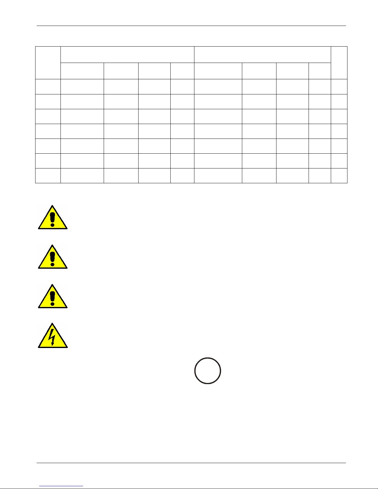
14.2 Fuses and Fuse Code for UL
Bussmann Div Cooper (UK) Ltd
(200 kARMS Symmetrical A.I.C.)
Ferraz Shawmut SA
(200 kARMS Symmetrical A.I.C.)
SIZE
Fuse
CODE
Current
(ARMS)
I²T
(A²sec)
Vac
Fuse
CODE
Current
(ARMS)
I²T
(A²sec)
Vac
Qty
15A FWC 16A10F 16 150 600
660 Grb
10-16
16 145 660 1
25A FWC 32A10F 32 600 600
660 Grb
10-32
32 740 660 1
35A FWP 40A14F 40 750 700
CP URC
14x51/40
40 700 660 1
45A FWP 50A14F 50 1800 700
CP URC
14x51/50
50 1500 660 1
60A FWP 80A22F 80 6600 700
CP URD
22x58/80
80 3800 660 1
90A - - - -
CP URQ
27x60/125
125 6970 660 1
110A - - - -
CP URQ
27x60/160
160 15000 660 1
Caution:
The Fuses must have I²t 20% less than thyristor's I²t.
Caution:
High speed fuses are used only for the thyristor protection and can not be used to
protect the installation.
Caution:
The warranty of thyristor is null if no proper fuses are used. See tab.
Warning:
The user installation must be protected by electromagnetic circuit breaker or by
fuse isolator.
CUS
LISTED
U
L
®
Page 46
CD Automation srl CD3200-1PH from 15A to 110A User’s Manual
46
14.3 Fuses and Fuse Code for CE
SIZE
Fuse and Fuse holder
CODE
Fuse CODE
Current
(ARMS)
I²T (max)
(A² sec.)
15A FFH1038/16A FU1038/16A 16 150
25A FFH1038/32A FU1038/32A 32 600
35A FFH1451/40A FU1451/40A 40 1650
45A FFH1451/50A FU1451/50A 50 2000
60A FFH2258/80A FU2258/80A 80 6550
90A FFH2258/125A FU2258/125A 125 14000
110A FFH2760/160A FU2760/160A 160 15000
Caution:
The Fuses must have I²t 20% less than thyristor's I²t.
Caution:
High speed fuses are used only for the thyristor protection and can not be used to
protect the installation.
Caution:
The warranty of thyristor is null if no proper fuses are used. See tab.
Warning:
The user installation must be protected by electromagnetic circuit breaker or by
fuse isolator.
Page 47

CD Automation srl CD3200-1PH from 15A to 110A User’s Manual
47
15 Maintenance
15.1 Trouble Shooting
Small problems sometimes can be solved locally with the help of the below tab of trouble shooting. If
you don’t succeed, contact us or your nearest distributor.
Symptom
Indication on
front unit
Possible reasons of the symptom Actions
Green LED
(Aux)
always light off
• No voltage auxiliary power
• Give auxiliary voltage supply
(see wiring diagram)
Green LED
(Aux) light on
Green LED
(ON) light off
• No input signal
• Reversed polarities of input signal
• Reset contact is open
• Provide to give input signal
• Reverse the input signal
polarity
• Make link on reset terminals
(see wiring diagram)
Thyristor unit
doesn’t go in
conduction with
input signal
Green LED
(Aux) light on
Green LED
(ON) light on
• Fuse failure
• Load failure
• Load connection interruption
• Thyristor faulty and always in open
circuit
With HB option the yellow led (HB) is
light on
• Substitute the fuse
• Check the load
• Check the wiring
• Substitute the faulty thyristor
Load current
flows also with no
input signal
Green LED
(ON)
always light off.
• Wrong wiring
• Short circuit on thyristor
If there is HB option the red LED (SC) is
light on
• Check the load wiring
• Substitute the thyristor
Current flows at
nominal value but
Yellow LED (HB)
is light on
Yellow LED
(HB) light on
• HB circuit not tuned
• Current transformers not properly
wired
• Make HB calibration procedure
• Control current transformers
wiring
Current flows at
nominal value but
Red LED (SC) is
light on
Red LED
(SC) light on
• HB circuit not tuned
• Make HB calibration procedure
Thyristor unit
doesn’t work
properly
• Wrong input signal selection.
• Wrong input signal calibration (out
of range).
• Auxiliary voltage supply out of
limits
• Control input signal setting.
• Repeat input calibration
procedure.
• Verify the auxiliary voltage
supply
Page 48

CD Automation srl CD3200-1PH from 15A to 110A User’s Manual
48
15.2 Fans
The thyristor unit with forced ventilation uses fans that rotate permanently when the unit is supplied. In
case of fan failure, the heat-sink can be reach high temperature. In this case to give protection to
thyristor there is a thermal switch properly setted. The function of this switch is to open the input signal
until the heat-sink temperature falls below the setted value. This means that also with input signal in ON
condition the unit is switched OFF and the system can not work at full power. For this reason is
important to control periodically the fans status checking that are rotating.
15.3 Maintenance
For maintain a correct cooling, the consumer must clean the heat-sink and the protective grate of the
fans. The frequency of these operations depends on the atmospheric local pollution.
Check also that the screw of the power terminals and earth terminals are shut correctly
(see Diagram of control connection).
15.4 Repairing procedure
• Phone to CD Automation.
• Explain to Service Engineer the problem because sometimes it can be solved with a phone call.
If this is not possible, ship the unit to CD Automation or to your distributor.
• Write a fault description and give the name of your personnel to which refers.
• Use a rugged packaging to ship the unit.
15.5 Warranty condition
CD Automation gives a 12 months warranty to its products. The warranty is limited to repairing and
parts substitution in our factory and does exclude products not properly used and fuses.
Warranty does not include products with serial numbers deleted. The faulty product should be shipped to
CD Automation at customer’s cost and our Service will evaluate if product is under warranty terms.
Substituted parts remain of CD Automation property.
Page 49

CD Automation srl CD3200-1PH from 15A to 110A User’s Manual
49
16 Note
Page 50

CD Automation srl CD3200-1PH from 15A to 110A User’s Manual
50
ENG CD3200-1PH__15-110A - 10.DOC
 Loading...