

Page 1
www.cda.eu
SK320
Single oven
Installation, use and maintenance
Page 2

2
Contents:
3 Important information
5 Safety instructions
6 First use of the oven
7 Oven controls, functions and use
10 Electronic programmer/timer
11 Setting the current time
11 Minute minder function
12 Semi-automatic cooking
13 Automatic cooking
14 Cleaning and maintenance
16 Removing the appliance door
17 Replacing the appliance door
18 Removing the inner door glass
19 Changing the oven light bulb
20 Installation
22 Mains electrical connection
24 Troubleshooting
25 Energy Eciency Information
IMPORTANT: Please read the user instructions carefully before
using the appliance for the first time and before installing it.
Failure to install the oven, or to have it installed, as per the user
manual could invalidate the warranty. Any service calls relating to
misuse or incorrect installation could incur a service charge.
Page 3

3
Important
This appliance must only be used for the purpose for which it is
intended, i.e. domestic cooking. Any other use could be dangerous
and may lead to premature failure of the appliance.
The CDA Group Ltd cannot be held responsible for injuries or losses
caused by incorrect use or installation of this product. Please note that
CDA reserve the right to invalidate the guarantee supplied with this
product following incorrect installation or misuse of the appliance.
Under no circumstances should any external covers be removed for
servicing or maintenance except by suitably qualified personnel.
User information:
• Ovens become hot during and immediately after use.
• The oven door can become very hot during operation.
• After use, please ensure that the oven switches are in the ‘O’
position.
• Keep children away from the appliance when in use, and
immediately after use.
• Do not allow children to play with or on the appliance.
• Keep the oven door closed whilst grilling.
Appliance information:
Please enter the details from the appliance rating plate on to the
following page for reference, to assist CDA Customer Care in the
event of a fault with your appliance and to register your appliance for
guarantee purposes.
Page 4
4
Appliance Model
Serial Number
EU Declarations of Conformity:
This oven has been designed, constructed and marketed in
compliance with safety requirements of EU Directive 2014/35/EU (Low
voltage) and requirements of EU Directive 2014/30/EU.
This appliance has been manufactured to the strictest standards and
complies with all applicable legislation, including Electrical safety (LVD)
and Electromagnetic interference compatibility (EMC). Parts intended
to come into contact with food conform to 1935/2004/EC.
IMPORTANT INFORMATION FOR CORRECT DISPOSAL OF THE
PRODUCT IN ACCORDANCE WITH EC DIRECTIVE 2012/19/EU.
At the end of its working life, the product must not be disposed
of as urban waste. It must be taken to a special local authority
dierentiated waste collection centre or to a dealer providing this
service.
Disposing of a household appliance separately avoids possible
negative consequences for the environment and health deriving from
inappropriate disposal and enables the constituent materials to be
recovered to obtain significant savings in energy and resources. As a
reminder of the need to dispose of household appliances separately,
the product is marked with a crossed-out wheeled dustbin.
Page 5

5
Important
• Read the user instructions carefully before using the oven
for the first time.
• Follow the instructions for first use of the oven.
• Clean the oven regularly.
• Remove spills as soon as they occur.
• Always use oven gloves when removing shelves and trays
from the ovens.
• Do not allow children near the oven when in use.
• Do not allow fat or oils to build up on the oven shelves, grill
pan or oven base.
• Do not place any cooking utensils or plates directly on the
oven base.
• Always grill with the oven door closed.
• Do not grill food containing fat without using the grill pan
grid.
• Do not cover the grill pan grid, the oven walls or the base
with aluminium foil.
• Do not use the oven tray for roasting.
• Do not perform maintenance or cleaning of the oven
without first switching o the electricity supply. If the oven
has recently been used, allow to cool.
• Do not place hot enamel parts in water. Leave them to
cool first.
• Do not allow vinegar, coee, milk, saltwater, lemon or
tomato juice to remain in contact with enamel parts.
• Do not use abrasive cleaners or powders that will scratch
the surface of the enamel.
• Do not attempt to repair the internal workings of your oven.
Page 6

6
• Do not dismantle any parts without disconnecting the oven
from the mains power supply.
• Do not use the appliance if any part is broken (e.g. door
glass). Disconnect it from the mains power supply and
contact CDA Customer Care.
• The cooling fan may run even long after the oven has
finished cooking.
• During use the appliance becomes very hot; do not touch
the heating elements inside the oven or the interior.
• Do not allow children near the oven when in use, nor to play
with it.
• This appliance is not intended for use by persons (including
children over the age of 8) with reduced physical, sensory
or mental capabilities, or lack of experience or knowledge,
unless they have been given supervision or instruction
concerning use of the appliance by a person responsible for
their safety.
• Children may not perform cleaning and maintenance
unsupervised.
• Do not harsh abrasive cleaners or sharp metal scrapers to
clean the oven door glass since they can scratch the
surface, which may result in shattering of the glass.
• Abrasive detergents and steam cleaning equipment should
not be used for cleaning.
• The oven may require increased ventilation on the before
first use steps. This can be achieved either from an open
window or the use of an extractor.
• Clean up any major spills to avoid the risk of fire or
excessive smoke.
Page 7

7
• Do not hang towels or cloths on the oven handle at any
time.
• Ensure that the oven is cool and power to the appliance
has been turned o before carrying out any cleaning or
maintenance including door removal.
• Always wear adequate PPE (Personal Protective Equipment)
when carrying out any handling, maintenance or cleaning.
Page 8
8
First use of the oven
First use
• The metal casing of this appliance has been coated with a
preservative to protect it during transport and storage. This should
be removed during installation by using a non-abrasive stainless
steel cleaner. Always follow the instructions given with the cleaner
being used.
• Before using the oven for the first time we recommend that you
clean the oven with soapy water, rinse carefully. Set the current
time on the programmer as per page 13. Heat on each of the
below programmes at maximum temperature for the specified time.
A slightly unpleasant smell may be produced, caused by grease
remaining on the oven elements from the production process.
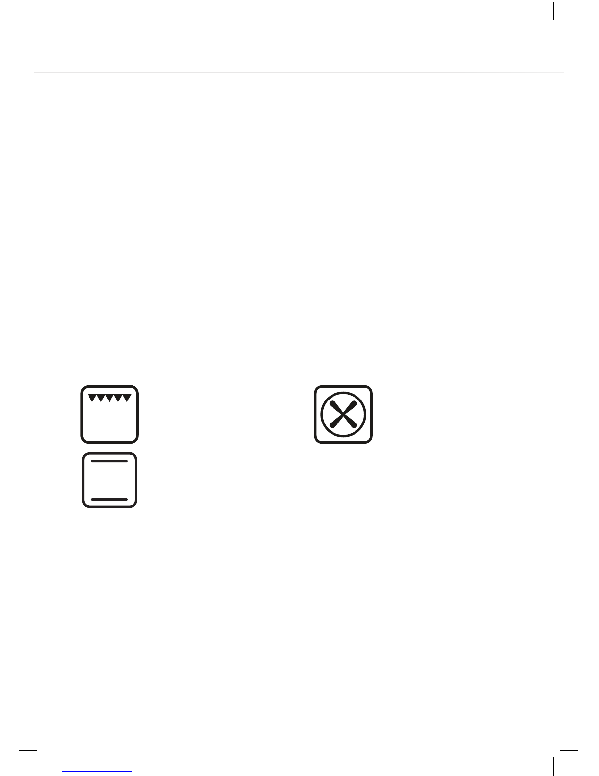
15 minutes full grill 60 minutes fan oven
60 minutes conventional oven
Please note:
• This oven has been fitted with a cooling fan to achieve maximum
eciency and to maintain low surface temperatures. The cooling fan
will switch on automatically when the oven switches on. It is normal
for the cooling fan to run for an hour or more after use, depending
on the duration, temperature and type of cooking programme used.
IMPORTANT - Always operate within the temperature ranges
stated for each function on pages 9 - 11.
Page 9
9
Oven controls and use
IMPORTANT: You must set the current time on the oven
programmer, as per page 13, for the oven to operate properly.
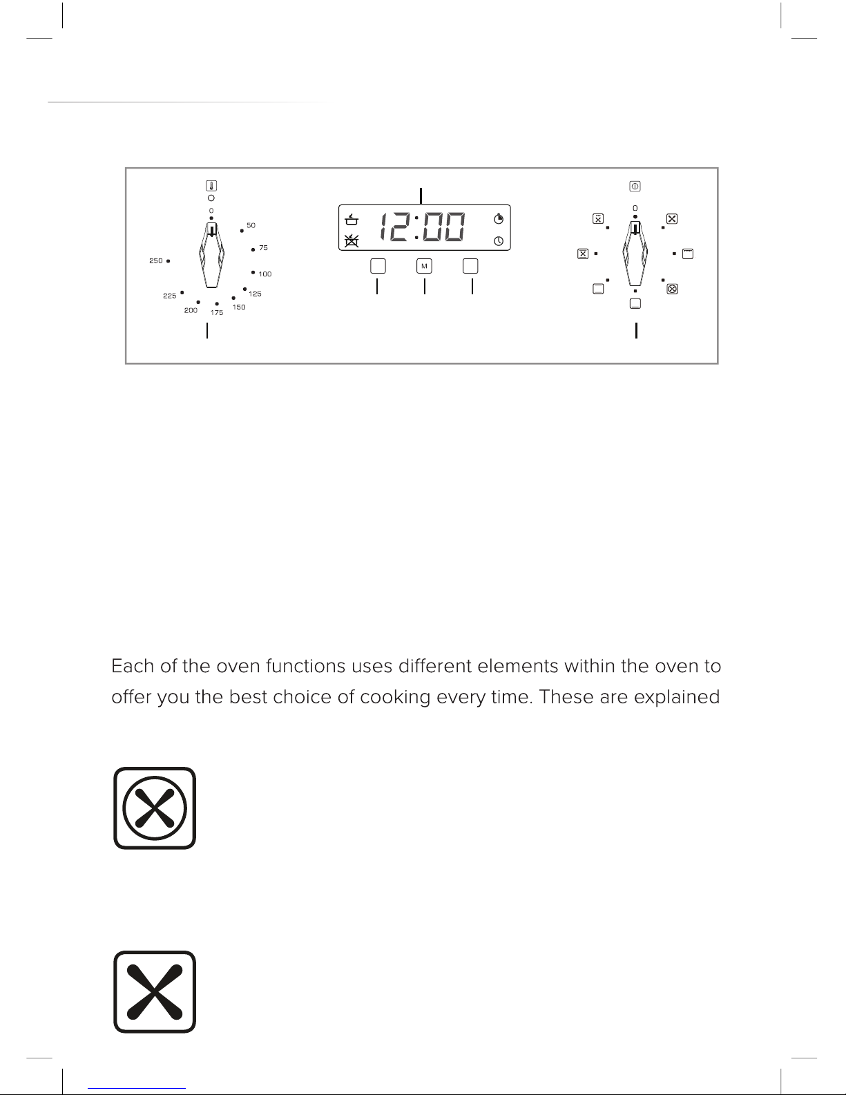
Cooking function knob (B in Fig. 1)
To set the function, turn the cooking function knob (B in Fig. 1) to
the required function. You will need to set a temperature on all
functions except the defrost function. The neon indicator next to
the temperature knob will extinguish when the temperature has been
reached.
below and on the following two pages:
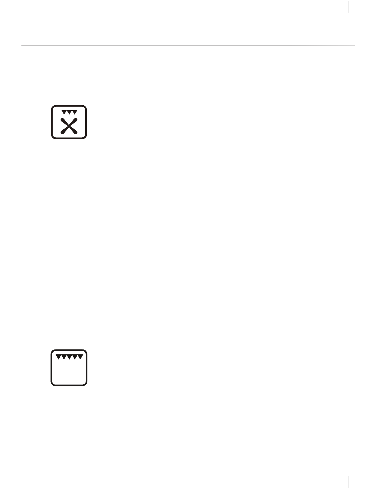
Fan oven
This function uses the circular heating element with a
temperature between 50°C and 250°C. The fan then
circulates the hot air which helps to achieve uniform
heat distribution.
Defrost
This function uses the fan to circulate air, at ambient
_
+
Fig. 1
A B
B C D
F
Page 10
10
temperature, within the oven which helps to accelerate
the defrosting process. 1 kg takes approximately 1 hour
to defrost, depending on the type of food.
Fanned Grill
This function radiates the heat from the grill element but
also uses the fan to circulate the hot air. The hot air is
distributed over and under the food that you are grilling.
This fully temperature variable grill is ideal for grilling
fish or other items whose appearance can be spoiled by
a normal grill function.
It can be set between 50°C and 250°C.
When fan grilling, please note:
• Always grill with the oven door closed.
• The grill pan does not need to be as close to the
grill as possible.
• Do not grill for more than 30 minutes at a time.
• Preheat the grill for up to five minutes with the
oven door closed.
Full Grill
This function radiates the heat from the grill element
and the top element.
This fully temperature variable grill is ideal for grilling a
full family meal. It can be set between 50°C and
250°C.
Page 11
11
When grilling, please note:
• Always grill with the oven door closed.
• Put the grill pan as close to the grill as possible.
• Do not grill for more than 30 minutes at a time.
• Preheat the grill for up to five minutes with the
oven door closed.
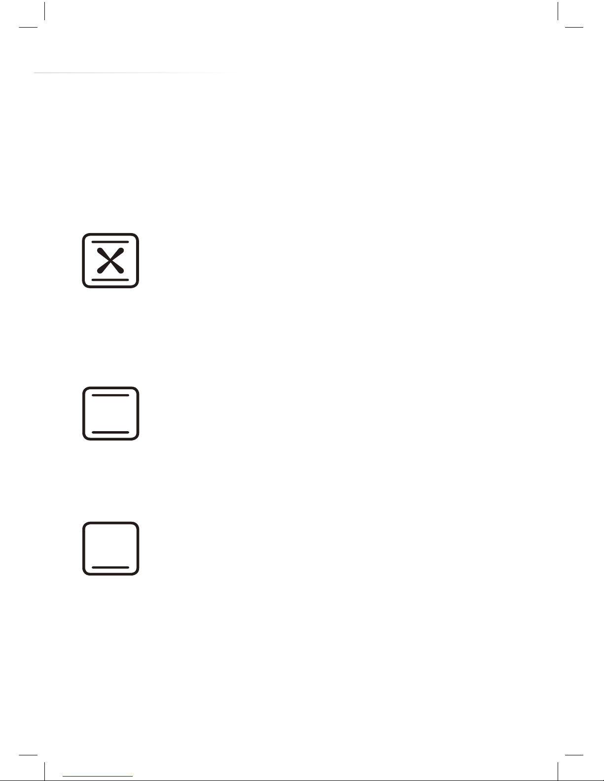
Fanned conventional
This function uses the upper and lower heating
elements and the fan with a temperature range of 50°C
to 225°C. The fan circulates the heated air around the
cavity meaning temperatures are achieved quicker and
cooking is more even.
Conventional
This function uses the upper and lower heating
elements with a temperature range of 50°C to 240°C.
Convection creates an ideal cooking zone in the centre
of the oven, ideal for fruit cakes and pastries.
Warming
Using heat produced from the bottom element, this heat
setting creates an ideal environment for dough proving
and blind-baking
Page 12
12
Temperature knob (A)
• To set the temperature, turn the temperature knob clockwise to the
required temperature.
• Once the oven has reached the required temperature, the
• The temperature indicator lamp will light up when the oven
elements are in operation.
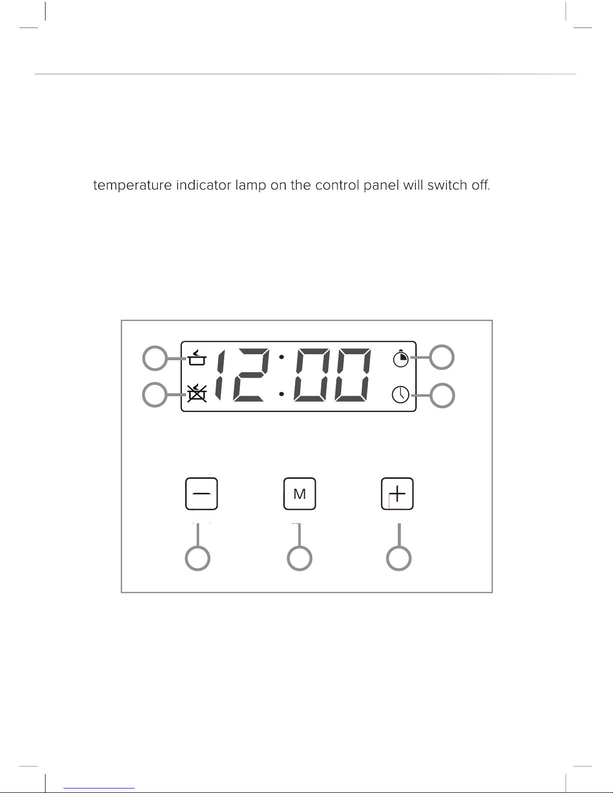
Electronic programmer/timer
1 - Cooking time indicator 5 - Decrease key
2 - End of cooking time indicator 6 - Mode key
3 - Minute minder indicator 7 - Increase key
4- Current time indicator
1
2
3
4
5
6
7
Fig. 2
Page 13
13
This oven’s electronic timer is equipped with touch control sensors.
Each registered touch of a sensor field is confirmed by a single beep.
It is advisable to keep the sensor fields clean at all times to avoid
errors in operation.
Setting the current time
After connection to the mains supply, or re-connection after a power
outage, the display will show ‘12.00’ and the clock symbol will flash.
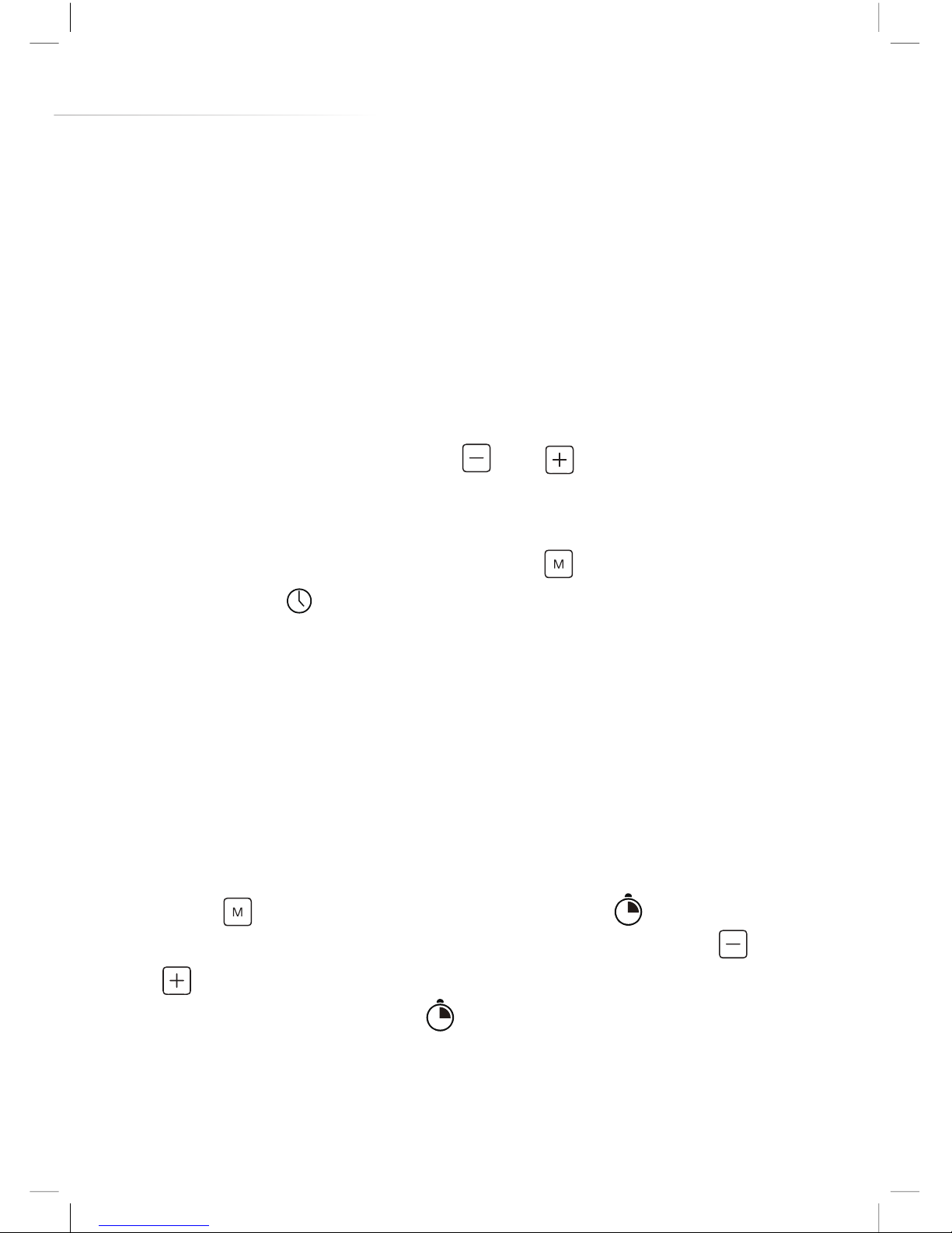
• Set the current time using the and sensors. After an
approximately 5 second wait, the time will be set.
• The time can be amended at any time by following these steps.
However, you will firstly need to press until the display shows
the flashing symbol.
Please note: The time must be set for the oven to work.
Setting the minute minder function
The minute minder function can be set at any time, regardless of the
state of activity of the oven. The minute minder can be set anywhere
from 1 minute to 23 hours and 59 minutes.
• Press
until the display shows the flashing symbol.
• Set the desired duration of the minute minder using the and
sensors. After an approximately 5 second wait, the minute
minder will be set and the symbol will be solidly lit.
• Press any of the three sensors in order to deactivate the acoustic
signal that sounds once the minute minder time has elapsed. The
timer will then revert to showing the current time.
Page 14
14
Please note:
deactivate automatically after approximately 2 minutes.
Cancelling the minute minder function
The minute minder function can be cancelled at any time.
• Press to select the minute minder settings. This is indicated by
the symbol .
• Press the sensor until the time returns to 0.00 and wait 5
seconds.
Semi-automatic cooking
This function allows for a cooking time to be set. When the set time
will sound to alert the user.
To switch on semi-automatic cooking
• Set the desired oven function and temperature.
• Press the menu sensor until the display illuminates the symbol
and the timer display shows 0.00.
• Set the required cooking time using the timer left and right
sensors. The cooking time that can be set ranges from between
1 minute and 10 hours. After an approximately 5 second wait, the
time will be set and the symbol will remain lit.
• Once the set cooking time has elapsed the set function will be
symbol will flash. Press any of the three sensors in order to
deactivate the acoustic signal that sounds once the cooking time
has elapsed. The timer will then revert to showing the current time.
Page 15

15
• Switch both control knobs to the o position.
To cancel semi-automatic cooking
The semi-automatic function can be cancelled at any time. To do this,
simply press until the display shows the symbol and use the
sensor to return the timer display to 0.00.
Please note: The acoustic signal, if not switched o manually, will
deactivate automatically after approximately 2 minutes.
Automatic cooking
This function allows for a duration and an end time to be set for
cooking. With this, the oven will start cooking automatically due to
the set duration determining how long before the end time that the
function will activate and begin cooking. For example, if you set the
cooking duration to 1 hour, and the end time to 15:30, then the oven
will activate the function at 14:30. When the set time elapses, the oven
will switch the set function o and an acoustic signal will sound.
To switch on automatic cooking
• Press
until the display illuminates the symbol and the timer
display shows 0.00.
• Set the required cooking time using the and sensors.
The cooking time that can be set ranges from between 1 minute
and 10 hours.
• The cooking time will be set after approximately 5 seconds. The
display will revert to showing the current time and the symbol
will be illuminated.
Page 16
16
• Press until the display illuminates the symbol and it begins
to flash.
• Set the end of cooking time using the and sensors.
The end of cooking time can be set no more than 23 hours and 59
minutes ahead of the current time.
• Set the desired function and temperature using the relevant
control knobs. The automatic function will now be set. Once the
end of cooking time has been reached an acoustic signal will
sound and the symbol will flash. To deactivate the acoustic
signal, press any of the three timer sensors. Alternatively, the
signal will deactivate automatically after approximately 2 minutes.
• Switch both control knobs to the o position.
To cancel automatic cooking
The semi-automatic function can be cancelled at any time. To do this,
simply press until the display shows the symbol and use the
sensor to return the timer display to 0.00.
Please note: It is not possible to adjust the time (of day) setting whilst
the semi-automatic and automatic cooking functions are operational.
Cleaning and maintenance
Keeping your oven clean and well maintained helps to prolong the
fault-free lifespan of it and helps prevent your home from being
filled with odours. It is important that, before any cleaning or
maintenance is performed, you switch o the oven at the mains
supply. Do not start any cleaning or maintenance until the oven
has been allowed to cool completely.
Page 17

17
We recommend always wearing PPE (Personal Protective
Equipment) when carrying out any cleaning or maintenance.
Cleaning the oven exterior
As the oven has, glass, stainless steel and enamel surfaces you
should use a nonabrasive cleaner. Any abrasive cleaner (including Cif)
will scratch the surfaces and could erase the control panel markings.
Stainless steel can be eectively cleaned by simply using a dilute
solution of water and mild detergent and drying to a shine with a
clean cloth.
Proprietary stainless steel cleaners are available. We recommend
a microfibre cloth for stainless steel surfaces. If necessary, wipe
any area that has been cleaned using a damp soft cloth or tissue to
remove any residual cleaning fluid and then wipe dry with a clean, dry
cloth or tissue (such as kitchen towel).
Cleaning the oven interior
The oven should always be cleaned after use when it has been
allowed to cool down.
The cavity should be cleaned using a mild detergent solution and
warm water and then wiped dry with a suitable, clean cloth.
Suitable proprietary chemical cleaners may be used after first
consulting with the manufacturers’ recommendations and testing a
sample on a small area of the oven cavity. Abrasive cleaning agents
or scouring pads/cloths should not be used on the cavity surface.
IMPORTANT:
• Steam cleaners must not be used when cleaning this appliance.
Page 18
18
• Once care and maintenance is complete, ensure that all parts
are correctly replaced before using the oven.
Removing the appliance door
In order to allow for easier access into the oven cavity for cleaning, it
is possible to remove the door. Before removing the door, ensure that
you have an area prepared in which you can place the removed door.
This area should ideally be protected by something like a folded, dirtfree, towel to help prevent damage to surfaces and the door.
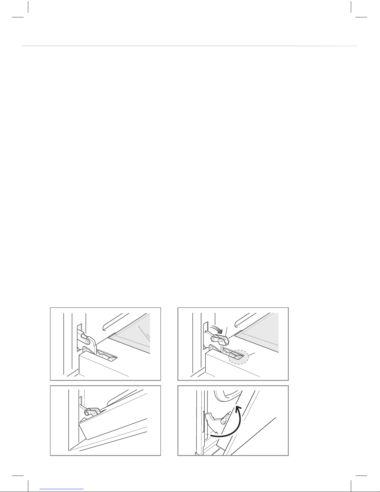
• Open the door to the full extent (1).
• Open the lever A completely on the left and right hinges (2).
• Raise and hold the door as shown in image 5 on page 19.
• Gently close the door (3) until left and right hinge levers A are
hooked to part B of the door (2).
• Withdraw the hinge hooks from their location following arrow C (4).
• Rest the door on the pre-prepared soft, clean surface.
B
B
C
`
A
1
2
3 4
Page 19
19
Replacing the appliance door
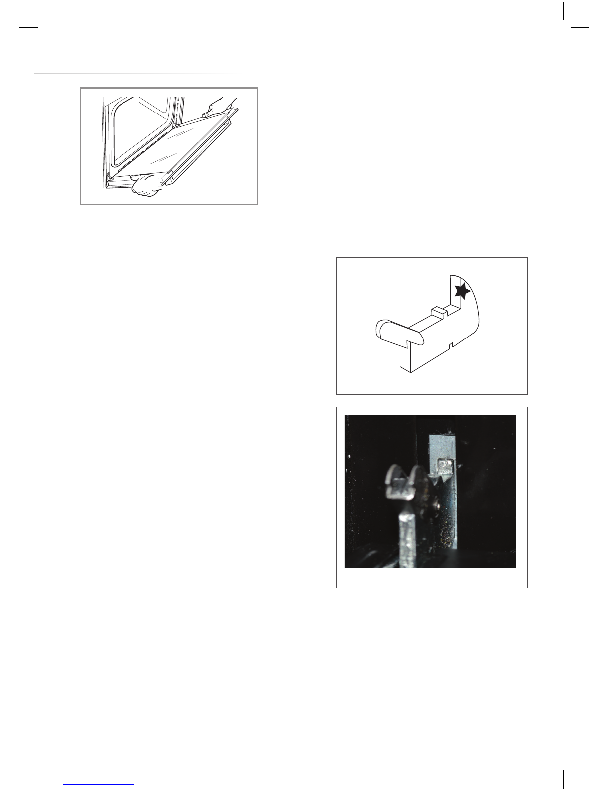
• Hold the door to the appliance in
the closed position and manoeuvre
the hinges so that the part of the
hinge, highlighted by the star in fig.
3, inserts into the hinge slot in the
cavity frame.
• Next, ensure the notch on the
underside of the hinge sits on the
lip of the hinge slot. Open the door
fully. Each hinge should be seated
in the same way as the hinge in
fig. 4. If it is not, follow the steps for
removing the door and try replacing
it again.
• Finally, lift the safety catch part of the hinges back into place so
that they are lying flat against the hinges.
Please note: If the hinge safety catches are not in the correct
place then the door and/or appliance may receive damage when
attempting to close the door.
Fig. 3
Fig. 4
5
Page 20
20
Removing the inner door glass
The inner pane of glass can be removed for cleaning purposes. To do
so, follow the steps below.
Important: Do not disassemble the door without it having been
removed from the oven as per page 18. Weight dierences could
cause the door to snap shut, causing damage to the oven and/or
the user.
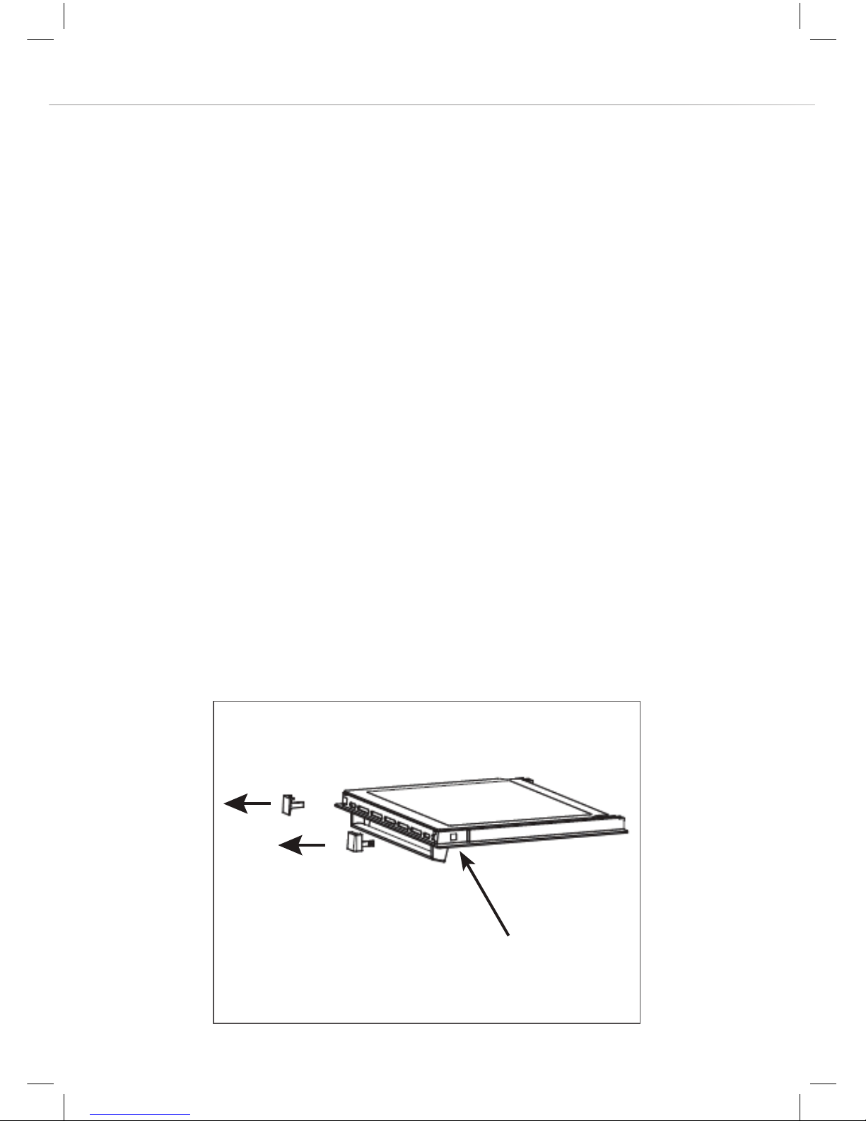
• Remove both door top corner pieces. These can be removed by
pressing in the arrow-marked tabs (indicated in image below) and
sliding the corner pieces in the direction indicated in the image
below.
• Lift the top edge of the glass slightly and then slide the lower edge
from its clips.
• After cleaning the glass, replacement is a reversal of the removal
process. Take care to replace the glass the correct way round -
the printed surface must be visible when the door is opened.
Tab
Page 21

21
Changing the oven light bulb
Important:
• Before any maintenance, the appliance must be disconnected
from the power supply. If the oven has been in use, let the oven
cavity and the heating elements cool down before attempting
any maintenance.
• Never use screwdrivers or other utensils to remove the light
cover. This could damage the enamel of the oven or the lamp
holder. Remove only by hand.
• Never replace the bulb with bare hands as contamination from
your fingers can cause premature failure. Always use a clean
cloth or gloves. Old bulbs may also be hot!
1 Remove all shelves and the grill pan from the oven.
2 Gently unclip the shelf support from its lower locating stud and
unhook the top to remove it. No tools are required here and the
stud should not be removed.
3 Carefully detach the glass cover from the lamp housing by sliding it
upward and then easing the bottom outward.
4 Carefully remove the old bulb and insert a new bulb suitable for
high temperatures (300°C) of the following specification; 230240V~, 50 Hz, 25W, G9 fitting.
5 Reattach the glass cover, pressing it firmly into position.
6 Replace the shelf support by locating the two hooks at the top and
clipping it into position on the fixing stud.
7 Replace all shelves and the grill pan as necessary.
Please note: The bulb replacement is not covered by your guarantee.
Page 22
22
Installation
Important! If installing this oven below a hob, ensure that the air
gap between the two appliances is observed. This gap is usually
detailed in the hob’s manual.
The installation of this appliance must be carried out by suitably
qualified personnel. We recommend seeking the help of another
person for the installation process. This appliance may have sharp
edges; always wear suitable PPE (Personal Protective Equipment).
If the oven is being installed into a built under oven housing unit
ensure that the front rail at the top of the unit is not installed as it
could restrict ventilation.
Ensure that air can flow freely around
the housing area. If the oven is being
installed into a fully enclosed built-under
oven housing unit it may be necessary
to cut a small slot in the top of the plinth
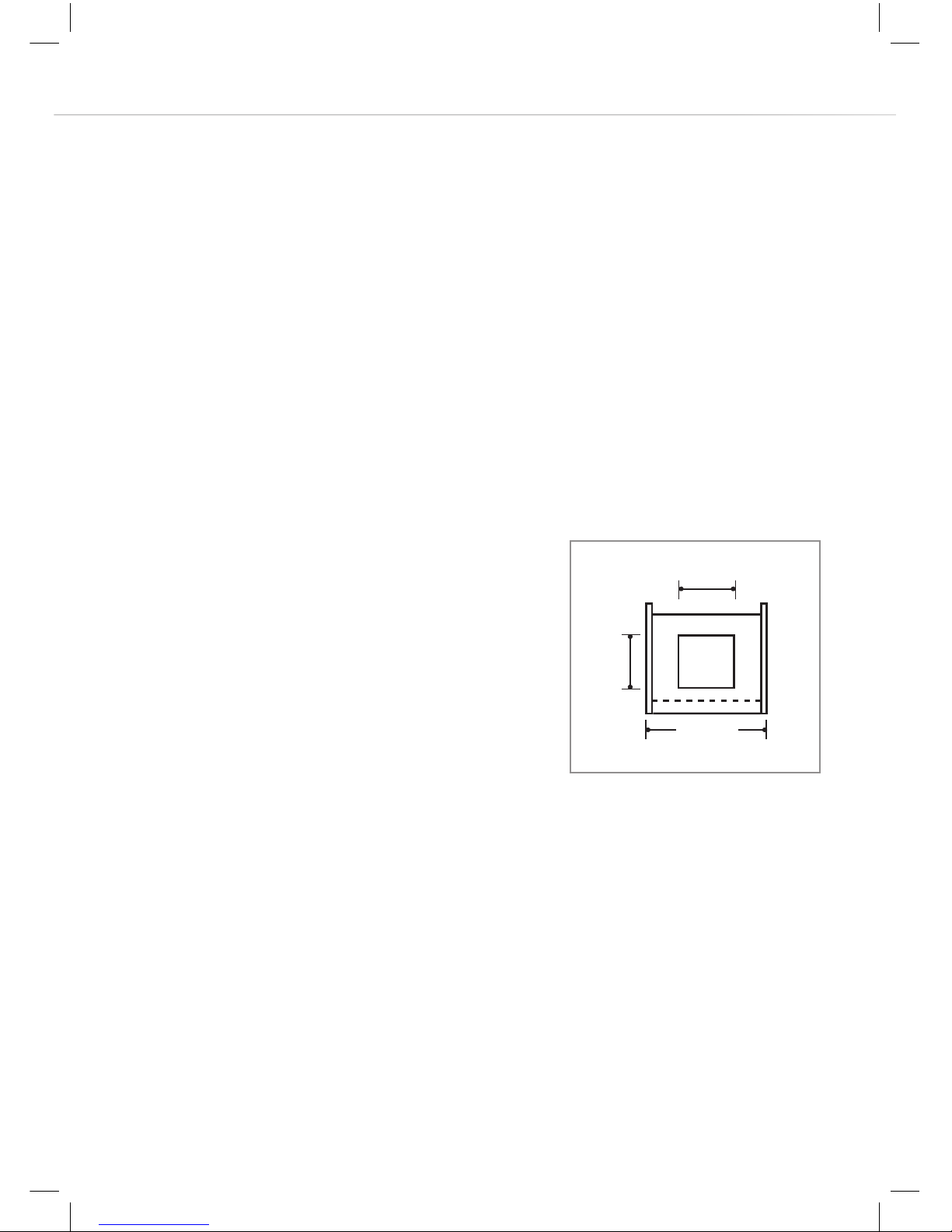
fitted under the unit. Cut a section 400 mm
wide and a minimum of 15 mm high to allow air to pass under the unit.
Alternatively cut a section 400 x 450 mm in the base of the carcass as
indicated in Fig. 5.
Failure to allow adequate ventilation to the appliance may result in
overheating or damage to adjacent units and could invalidate the
warranty.
This appliance is type X installation. The walls of the kitchen units
must be able to withstand temperatures of 100°C +.
Fig. 5
400
450
600
Page 23
23
When correctly installed ensure that there is a gap of 4 mm minimum
between the sides of the oven and adjacent furniture doors.
How to install your oven
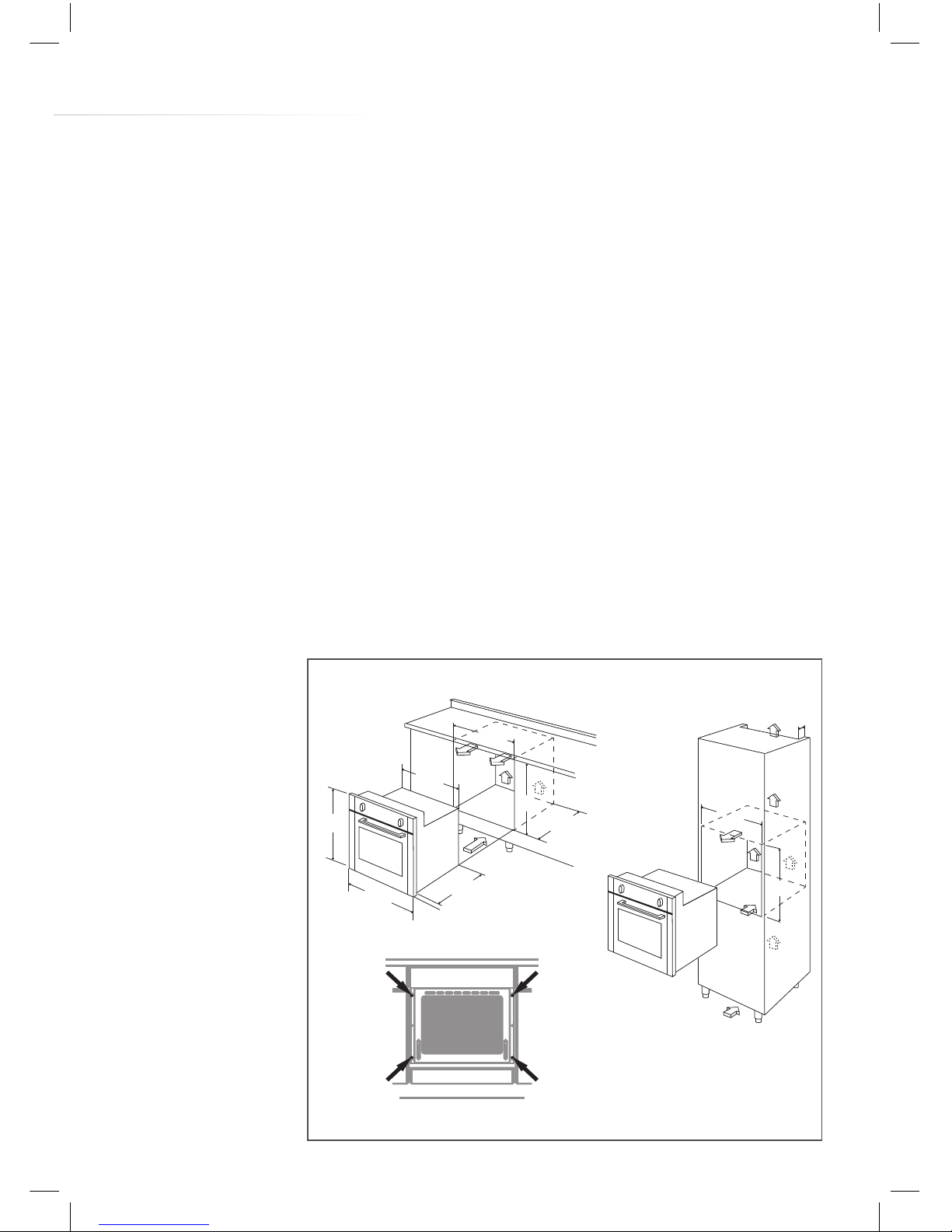
You will need the housing area in fig. 6 to fit your oven correctly.
The oven is designed to fit into a cabinet of 600 mm width. The oven
can be built in or built under the kitchen units, but you must ensure
that it is properly ventilated. In the diagram below the built-in oven
is ventilated by means of a space at the top of the kitchen cabinet.
There are many other methods of ventilating your oven - consult a
qualified engineer for advice.
Lift the oven carefully into position on the shelf, taking care NOT to
lift it by the door handle. If you open the oven door, you will see 4
screw holes, 2 on each side of the oven (image S fig. 6). The oven
should then
be secured to
the housing by
securing screws
into these holes.
Remember the
housing should
not be free
standing but
be secured to
the wall and/
or adjacent
fittings.
Fig. 6
40
564
600
600
560
564
595
595
547
554
20
S
Page 24
24
Mains electrical
connection
Warning! This appliance must be
earthed.
This appliance is intended to be
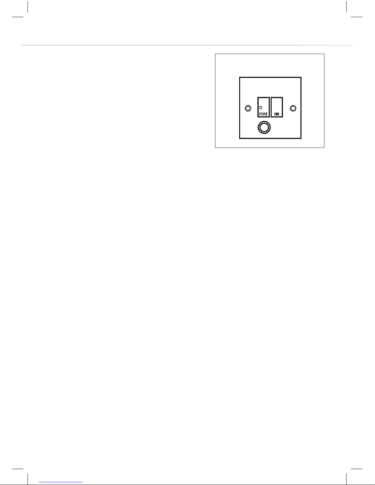
connected to fixed wiring by a double
pole switch, having a contact separation of at least 3mm in all
poles and protected by a 13A fuse. The switch must be positioned
no further than 2m from the appliance.
We recommend that the appliance is connected by a qualified
electrician, who is a member of the N.I.C.E.I.C. and who will comply
with the I.E.T and local regulations. The wires in the mains lead are
coloured in accordance with the following code:
GREEN AND YELLOW = EARTH BLUE = NEUTRAL BROWN =
LIVE.
As the colours of the wires in the mains lead for the appliance may
not correspond with the coloured markings identifying the terminals in
your spur box, proceed as follows:
1. The wire which is coloured green and yellow must be connected to
the terminal marked E (Earth) or coloured Green.
2. The wire which is coloured blue must be connected to the terminal
marked N (Neutral) or coloured Black.
3. The wire which is coloured brown must be connected to the
terminal marked L (Live) or coloured Red.
DOUBLE POLE
SWITCHED
FUSE SPUR OUTLET
13A
Page 25

25
Please note:
• The mains cable must only be replaced by a qualified electrician or
service engineer and must be of equivalent or better rating (i.e. 3 x
1.5 mm², HO5RR-F).
• This appliance is intended to be connected to the mains supply with
a cable of cross sectional area 1.5 mm².
• The current rating of the fuse or circuit breaker protecting this
appliance should be marked on the socket outlet.
• Assembly and electrical connection should be carried out by
specialised personnel.
• When installing this product we recommend you seek the help of
another individual.
• Should the mains cable be damaged or need to be replaced, it
should only be done so by a qualified electrician or engineer. The
terminal block on the appliance is clearly marked with regards to
the positions of live, neutral and earth.
Appliance electrical rating: 2160W
Page 26
26
Troubleshooting
If any of the above steps do not resolve your issue, please contact
CDA Customer Care to arrange a repair. Contact details are below.
Please have to hand all the details from your appliance’s rating plate
which can be found on the back of the oven and/or on the back of the
instruction manual/warranty card.
Important: All repairs must be carried out by qualified service
technicians.
Contact CDA Customer Care
A: Customer Care Department, The CDA Group Ltd, Harby Road,
Langar, Nottinghamshire, NG13 9HY
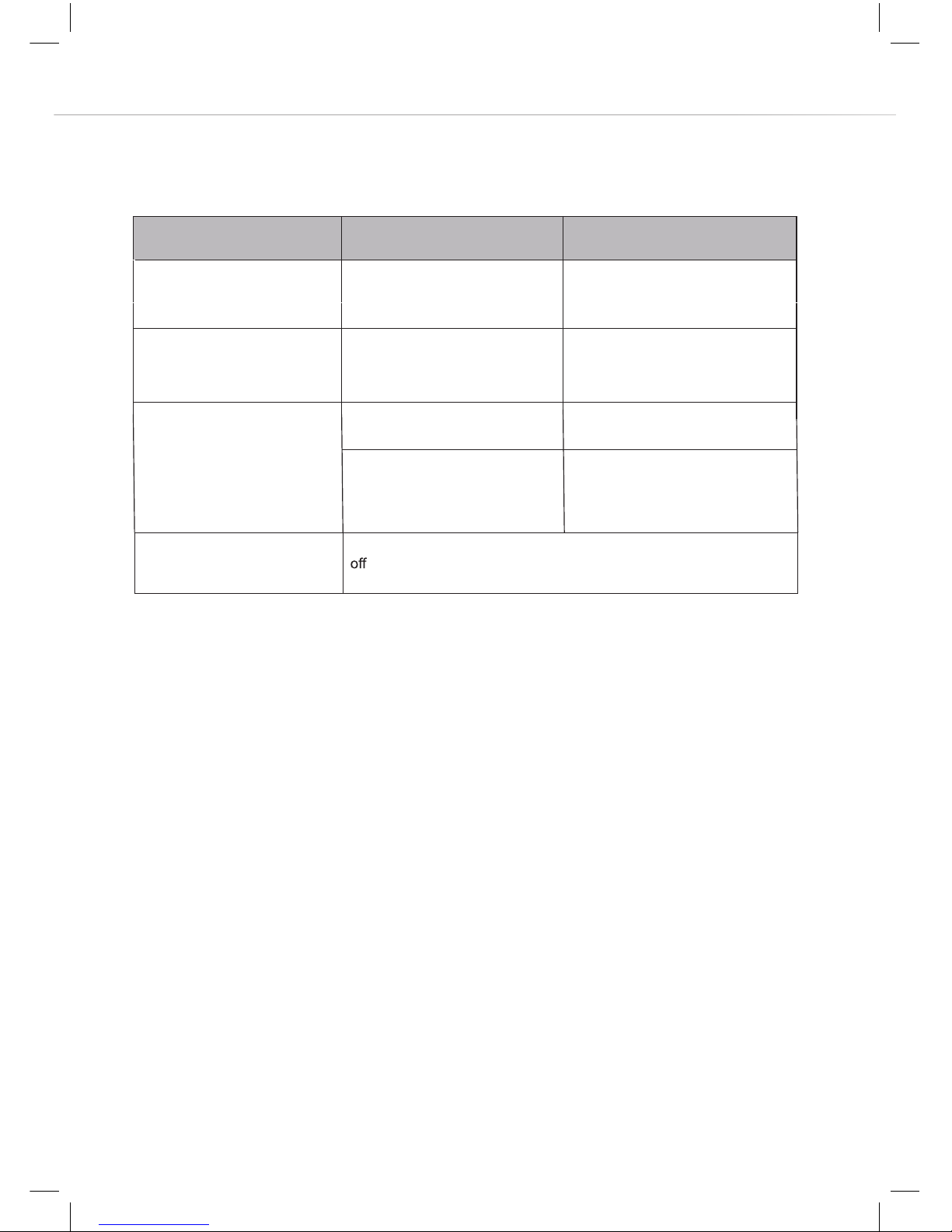
Problem Potential cause Potential remedy
The appliance does not work No power Check the fuse, replace if blown.
Oven lighting does not work. Loose or damaged bulb Replace the blown bulb (s e e
page 21).
Check the mains supply is on.
Oven is not heating
Temperature has not been set Set the desired temperature
using the temperature knob.
The cooling fan does not work
on a heated function
Risk of overheating! Unplug the appliance or switch
at the mains isolator. Contact CDA Customer Care.
If the programmer shows 12:00
(or 12:01 etc.) then the current
time has not been set.
Set the current time as per page
13.
Page 27
27
E & O E. All instructions, dimensions and illustrations are provided for guidance only. CDA reserve the
right to change specifications without prior notice.
Energy Eciency Information
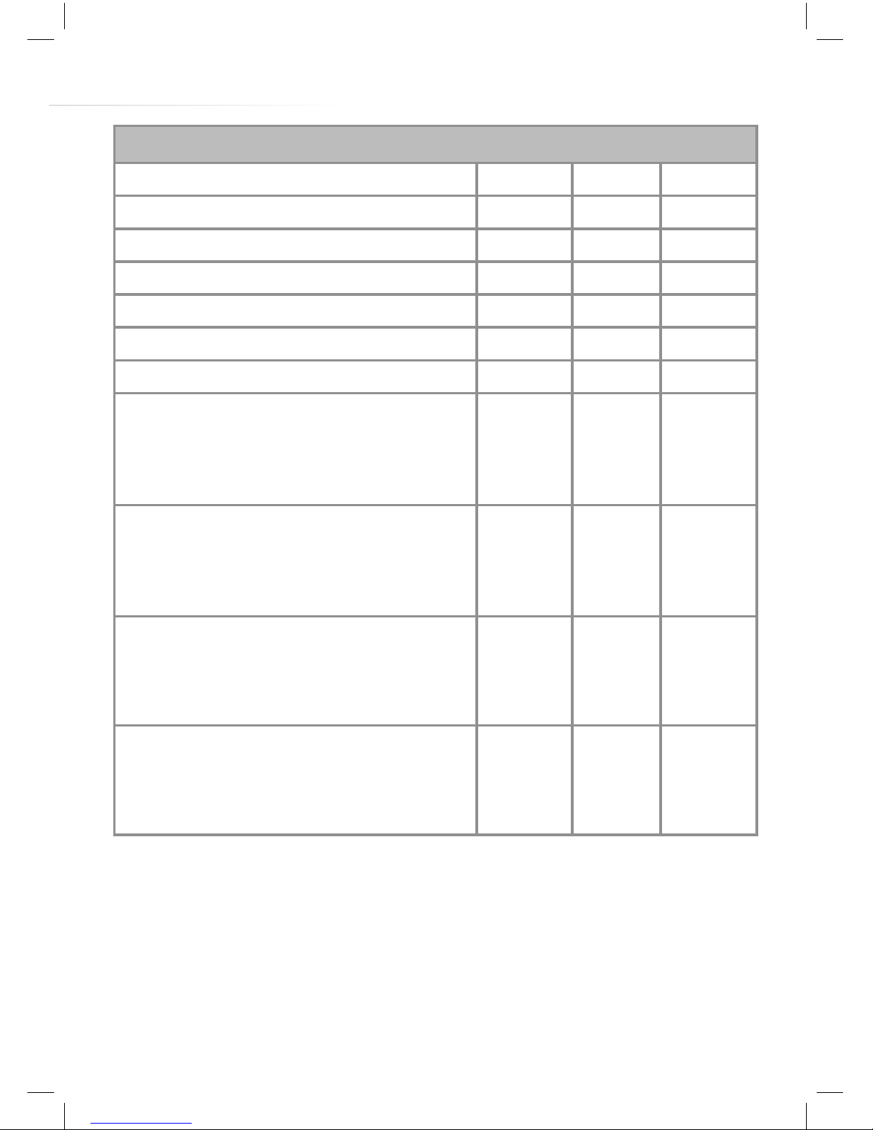
Attribute Symbol Value Units
Model identification SK320
Mass of the appliance M 37 kg
Energy eciency class A
Number of cavities 1
Heat source per cavity (electricity or gas) Electricity
Volume per cavity V 76 L
Energy consumption (electricity) required to heat
a standardised load in a cavity of an electric
heated oven during a cycle in conventional mode
per cavity (electric final energy)
EC
Electric cavity
0.93 kWh/cycle
Energy consumption (electricity) required to heat
a standardised load in a cavity of an electric
heated oven during a cycle in fan-forced mode
per cavity (electric final energy)
EC
Electric cavity
0.83 kWh/cycle
Energy consumption required to heat a standardised load in a gas-fired cavity of an oven during
a cycle in conventional mode per cavity (gas final
energy)
EC
Gas cavity
N/A MJ/cycle :
kWh/cycle
Energy consumption required to heat a standardised load in a gas-fired cavity of an oven during
a cycle in fan-forced mode per cavity (gas final
energy)
EC
Gas cavity
N/A MJ/cycle :
kWh/cycle
Page 28
www.cda.eu
Customer Care Department. The CDA Group Ltd, Harby Road, Langar, Nottinghamshire, NG13 9HY
T: 01949 862 012 F: 01949 862 003 E: [email protected]
For service or queries relating to your product please contact:
The Customer Care Department on 01949 862 012 or email [email protected]
For more information please contact:
The Sales Department on 01949 862 010 or email [email protected]
 Loading...