

Page 1
Customer Care Department • The Group Ltd. • Harby Road • Langar • Nottinghamshire • NG13 9HY
T : 01949 862 012 F : 01949 862 003 E : customer.care@cda.eu W : www.cda.eu
www.cda.eu
HNG7410FR
Indu-Gas Hob
Installation, Use and Maintenance
Page 2
2
Important
The manufacturer cannot be held responsible for injuries or
losses caused by incorrect use or installation of this product.
Please note that we reserve the right to invalidate the
guarantee supplied with this product following incorrect
installation or misuse of the appliance.
• This appliance can be used by children aged from 8
years and above and persons with reduced physical,
sensory or mental capabilities or lack of experience
and knowledge if they have been given supervision or
instruction concerning use of the appliance in a safe way
and understand the hazards involved.
• Children shall not play with the appliance.
• Cleaning and user maintenance shall not be made by
children without supervision.
Under no circumstances should any external covers be
removed for servicing or maintenance except by suitably
qualified personnel.
Appliance information:
Please enter the details on the appliance rating plate below for
reference, to assist CDA Customer Care in the event of a fault with
your appliance and to register your appliance for guarantee purposes.
Appliance Model
Serial Number
Page 3

3
CE Declarations of Conformity:
This appliance has been manufactured to the strictest standards and
complies with all applicable legislation, including Gas safety, Electrical
safety (LVD) and Electromagnetic interference compatibility (EMC).
Parts intended to come into contact with food conform to EEC/89/109.
IMPORTANT INFORMATION FOR CORRECT DISPOSAL OF THE
PRODUCT IN ACCORDANCE WITH EC DIRECTIVE 2002/96/EC.
At the end of its working life, the product must be taken to a special
local authority waste collection centre or to a dealer providing
appliance recycling services.
Disposing of a household appliance separately avoids possible
negative consequences for the environment and health. It also
enables the constituent materials to be recovered, saving both energy
and resources. As a reminder of the need to dispose of household
appliances separately, the product is marked with a crossed-out
wheeled dustbin.
Please note:
• Gas hobs become hot and remain hot during and
immediately after use. Do not touch the pan stands,
burners or hob spill tray until the appliance has been
allowed to cool.
• Keep children away from the appliance when in use.
• After use, please ensure that the gas taps are in the ‘O”
position.
• Ensure that the appliance is correctly adjusted for the type
of gas available before installation.
Page 4

4
• The use of a gas appliance produces heat and humidity
in the room in which it is installed. Ensure that the room
is well ventilated, either by the use of natural ventilation
outlets (e.g. windows) or a ducted extractor.
• This hob (Class 3) has been designed for use only as a
cooking appliance. Any other use (e.g. heating rooms)
should be considered incorrect and potentially dangerous.
• This appliance is adapted for the following markets: GB, IE
• Induction hobs become hot and remain hot during and
immediately after use. Do not touch the hob until it has
been allowed to cool.
• Never use the hob top for storage.
• Pan handles should never stand out beyond the edge of
the worktop. This will ensure children cannot reach them.
• Do not lean over the hob when it is in use.
• Follow the cleaning instructions carefully.
• Ensure the base of the saucepan is clean and dry before
placing it on the hob.
• Avoid hard shocks from cookware – the vitroceramic glass
surface is highly resistant but not unbreakable.
• Do not place hot lids flat on the hob top. A “suction” eect
could cause damage to the hob.
• Do not drag cookware across the hob top: in the long
term, this could cause damage to the hob.
• Do not store cleaning or flammable products in the unit
below the hob.
• Always use appropriate cookware for the induction zone
or gas burner in use.
Page 5

5
• Do not cook unopened tins of food directly on the hob.
• Never put cooking foil or plastic materials on the ceramic
surface when the hob is hot. These materials could melt
and cause damage to the hob.
• Do not use the hob if the glass surface is cracked or
damaged to prevent the risk of electric shock. Disconnect
it from the power supply.
• Ensure that the power cables of connected electrical
appliances near the hob are not in contact with the
cooking zones.
• Prior to installation, ensure that the local distribution
conditions (nature of the gas and gas pressure) and the
adjustment of the appliance are compatible.
• This appliance is not connected to a combustion products
evacuation device. It shall be installed and connected in
accordance with current installation regulations. Particular
attention shall be given to the relevant requirements
regarding ventilation.
• The use of a gas cooking appliance results in the
production of heat, moisture, and products of combustion
in the room in which it is installed. Ensure that the kitchen
is well ventilated especially when the appliance is in use:
Keep natural ventilation open or install a mechanical
ventilation device (mechanical extractor hood.
Page 6

6
Gas emergency services 0800 111 999 (This is a 24 hour
emergency line).
If you smell gas, think you have a gas leak, or are worried
that fumes containing carbon monoxide are escaping from a
gas appliance, please call the free Gas Emergency Services
emergency line immediately on 0800 111 999. Also:
• Open all doors and windows to ventilate the property.
• Do not turn on/o any electrical switches.
• Extinguish all naked flames, do not smoke, strike
matches or do anything which could cause ignition.
• If there are any electrical security entry phones/locks,
please open door manually.
FOR THOSE WITH HEART PACEMAKERS OR ACTIVE
IMPLANTS:
The function of this hob conforms to current
electromagnetic interference standards and thus is in
total compliance with legal requirements (2004/108/CE
directives).
To avoid interference between your hob and a pacemaker,
your pacemaker must be designed and programmed in
compliance with the regulations that apply to it. As such,
CDA guarantee only that our product is compliant.
With regard to the compliance of the pacemaker or any
potential incompatibility, you should obtain information from
the manufacturer or your attending physician.
Page 7

7
Cooking on Induction
The principle of induction cooking is based on magnetic eect.
When you put your cookware on an induction zone and switch it on,
the electronic boards in the hob produce induced currents in the base
of the cookware and instantly raise its temperature. This heat is then
transferred to the food inside the cookware.
The best cookware to use with induction cooking has thick flat bases,
as the heat will be better distributed so cooking more evenly.
Most cookware is compatible with induction cooking. There are three
ways to check the suitability of your cookware:
1. Use a magnet to see if the base of the pan is magnetic: if the
magnet sticks, then the cookware is compatible.
2. Place the pan on one of the cooking zones switched on to power
level 4: If the display remains on, then the cookware is
compatible. If the display flashes, the cookware cannot be used on
an induction hob.
3. Check the instructions or packaging of the pans for the symbols
indicating suitability for use with induction.
Page 8
8
Fig. 1
3
5
2
4
1
11
10
9
12
8
7
6
15
13
Fig. 2
14
16
Page 9

9
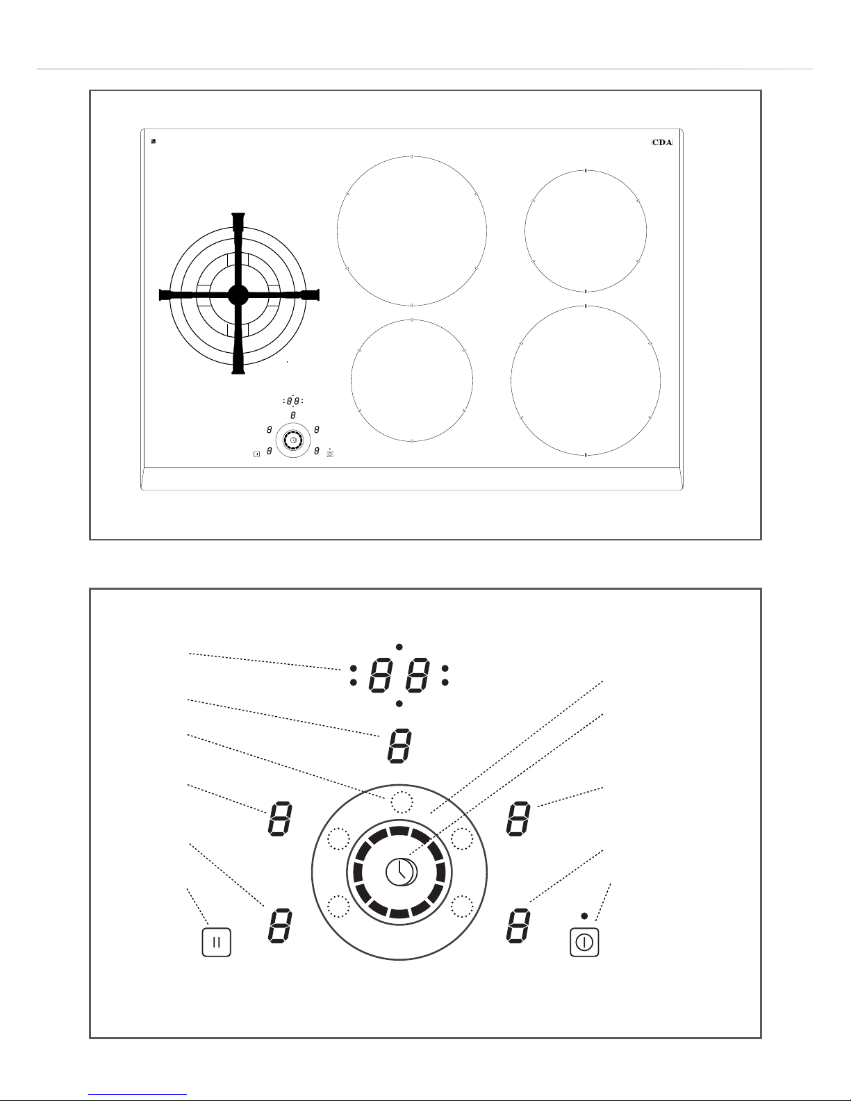
Key to Figs 1 & 2
Gas burner:
1. Wok burner 5.0kW
Induction zones:
2. Rear middle 2.3kW (3.0kW with booster) 215mm
3. Rear right 1.4kW 175mm
4. Front right 2.3kW (3.0kW with booster) 215mm
5. Front middle 1.4kW 175mm
Control panel:
6. Timer display
7. Pause key
8. On/O key
9. Zone display - front middle
10. Zone display - rear middle
11. Zone display - wok burner
12. Zone display - rear right
13. Zone display - front right
14. Circular slider groove
15. Timer key
16. Zone selection point (quantity 5, not marked on hob)
Page 10
10
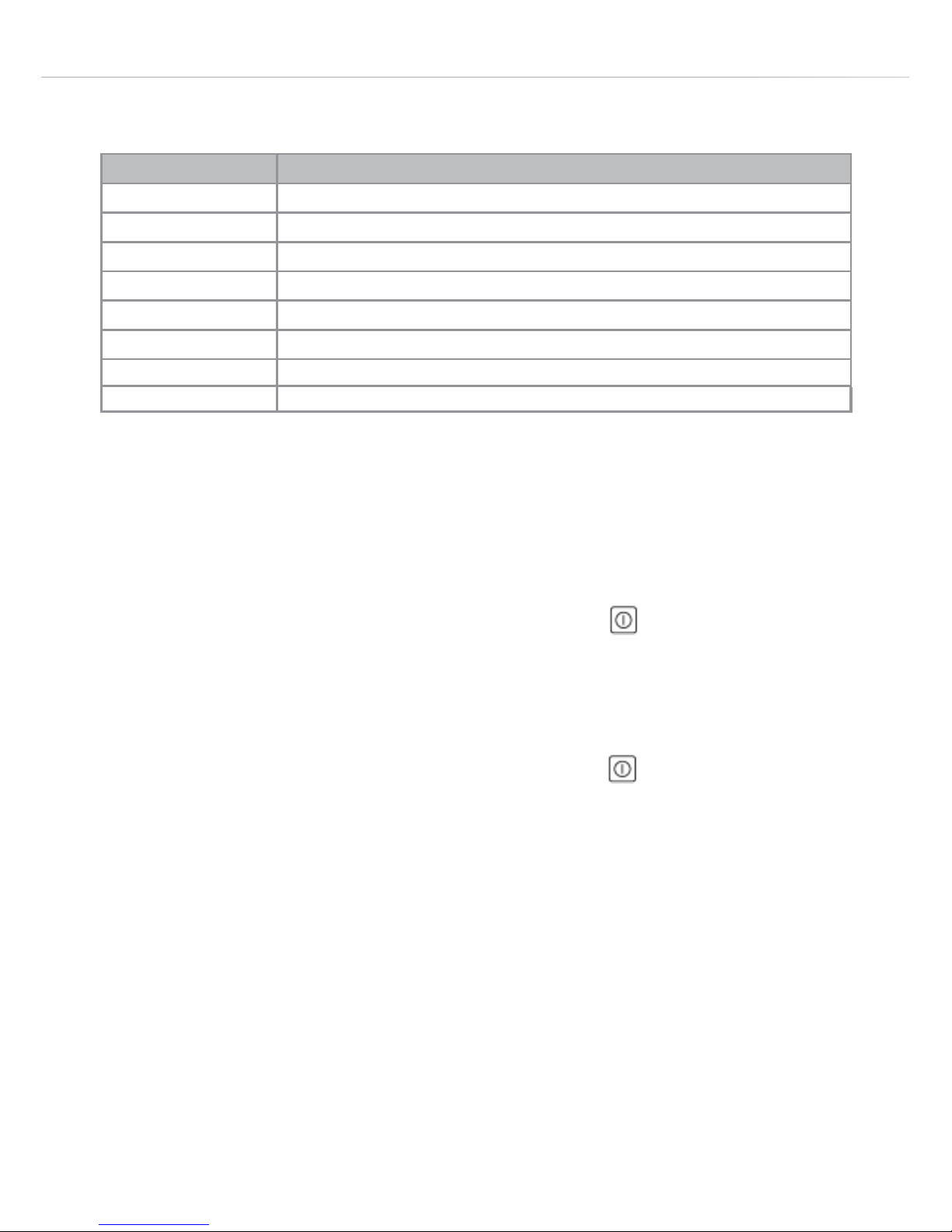
The table below oers guidance as to what each power level is for.
Using Your Hob
To switch the hob on
To switch the power on, touch the “On/O” key for approximately
two seconds. All five zone displays will flash “0”.
To switch the hob o
To switch the power o, touch the “On/O” key for approximately
one second. The zone displays will either show nothing, or the ones
for the induction zones will display “H” if their corresponding zones
are hot.
Please note: If no cooking zones are switched on within
approximately ten seconds, the hob will switch o automatically.
Power level Type of cooking
0 Switched o
1/2 Melting (butter/chocolate) or keeping food warm
2/3 Keeping food hot or to heat small quantities of liquid
3/4 Heat larger quantities of liquid (sauces etc.)
4/5 Slow boiling, e.g spaghetti, soups, stews, potatoes
6/7 Gentle frying
7/8 Browning meats, frying fish, omelettes
9 Fast frying steaks
Page 11

11
To switch a cooking zone on
• Touch the “Zone selection point” for the zone required to activate
its setting mode (The “Zone display” becomes brighter to show it is
activated).
Note: The “Zone selection points” are not marked with printing
on the panel but are at the closest parts of the “Circular slider
groove” to the zone displays.
• Then, use the “Circular slider groove” to control the power level
by touching anywhere around its length, or by sliding your finger
around it. Sliding clockwise increases the power level or sliding
anti-clockwise decreases the power level.
• After setting a zone on the zone setting, it remains activated for
a few seconds before the “Zone display” dims back to its normal
level. It is necessary to wait for this before you can switch another
zone on.
To change the power level after it has been set
• To increase the power level for a zone: Activate the zone’s setting
mode by touching the “Zone selection point” for that zone, then
slide your finger around the slider clockwise.
• To reduce the power level for a zone: Activate the zone’s setting
mode by touching the “Zone selection point” for that zone, then
slide your finger around the slider anti-clockwise.
• After changing a power level, the zone’s setting mode remains
activated for a few seconds before the “Zone display” dims back to
its normal level. It is necessary to wait for this before you can set
another zone.
Page 12

12
To switch a cooking zone o
• Touch the “Zone selection point” for the zone required to activate
its setting mode (The “Zone display” becomes brighter to show it is
activated).
• Then, use the “Circular slider groove” to reduce the power level to
“0”, by sliding your finger around it anti-clockwise.
• After reducing the power level to zero the zone switches o and
its setting mode remains activated for a few seconds before the
“Zone display” dims back to its normal level. It is necessary to wait
for this before you can change the setting of another zone.
When all the zones are at zero, the hob will switch o automatically
after approximately ten seconds.
Alternatively, to switch o the hob immediately, touch and hold the
“On/O” key for approximately one second.
Pause function
When one or more heating zones are active it is possible to pause
all cooking temporarily without losing the settings for the individual
zones. Induction cooking can then be resumed at the same settings
when the interruption is over. This is particularly useful when
answering the phone or during other interruptions while cooking.
To set the pause function
Touch the pause key for one second. All “Zone displays” show “l l”
to show that the pause function is activated.
Page 13

13
To cancel the pause function
Touch the pause key for one second, then within five seconds
touch the “Circular slider”. Cooking will resume at the same settings
as before the pause function was activated.
Booster
The hob is equipped with a booster function, allowing a higher power
level than the maximum for approximately ten minutes. This is only
applicable to the front right and rear middle zones.
To turn on the booster function:
• Touch the “Zone selection point” for the zone required to activate
its setting mode (The “Zone display” becomes brighter to show it is
activated).
• Then, use the “Circular slider groove” to increase its power level
beyond “9” and to “P”, by sliding your finger around it clockwise.
To turn o the booster function:
• Touch the “Zone selection point” for the zone required to activate
its setting mode (The “Zone display” becomes brighter to show it is
activated).
• Then, use the “Circular slider groove” to decrease its power level
from “P” to any lower level, by sliding your finger around it anti-
clockwise.
Note: The hob is fitted with a power management system to limit the
total power used. When using the booster on one or more zones this
function may limit the power being used by other zones.
Page 14

14
Timer
The hob is equipped with a timer that allows a finish time to be set for
the end of cooking on any zone, between a minimum of one minute
and a maximum of 99 minutes.
To set the timer
• Touch the “Zone selection point” for the zone required to activate
its setting mode.
• Use the “Circular slider groove” to select the power level required.
• Touch the “Timer” key a few times to select the tens of the time
required: The “Timer” display shows “00”, “10”, “20”, “30”, ”40”......
• When the required number of tens shows, use the “Circular slider
groove” to select the units of the time required: The display shows
“x1”, “x2”, “x3”, ”x4”......
• When the required number of units shows, wait for five seconds
and the timer will be set.
• At the end of the set cooking time the zone switches o, also the
“Timer” key flashes “00” and the hob beeps.
To cancel the beeper: touch the “Timer” key once.
Page 15

15
To cancel the timer
• Touch the “Zone selection point” for the zone required to activate
its setting mode.
• Touch the “Timer” key to select the timer option: The “Timer”
display shows the time remaining.
• Then, use the “Circular slider groove” to decrease its time setting
to “0”, by sliding your finger around it anti-clockwise.
Please note: Cancelling the timer will not switch o the zone. You
should switch o the zone manually if required.
Minute Minder
When no cooking zones are being used, the timer can be used as a
minute minder.
To Set the Minute Minder
• Switch on the hob.
• Do not switch any zones on.
• Touch the “Timer” key a few times to select the tens of the required
time: The “Timer” display shows “00”, “10”, “20”, “30”, ”40”......
• When the required number of tens shows, use the “Circular slider
groove” to select the units of the time required: The display shows
“x1”, “x2”, “x3”, ”x4”......
• When the required number of units shows, wait for five seconds
and the timer will be set.
• At the end of the set cooking time the “Timer” key flashes “00” and
the hob beeps.
To cancel the beeper: touch the “Timer” key once.
Page 16

16
To cancel the minute minder
• Touch the “On/O” key for approximately two seconds to switch
the hob back on.
• Touch the “Timer” key to select the timer option: The “Timer”
display shows the time remaining.
• Then, use the “Circular slider groove” to decrease its time setting
to “0”, by sliding your finger around it anti-clockwise.
• The minute minder is now cancelled.
Residual heat indicators
The hob is equipped with residual heat indicators to warn when any
of the induction zones are still hot to the touch after cooking. An “H”
will show in the relevant “Zone” display after cooking until the zone is
at a safe temperature to touch.
In the event of a power cut, the residual heat indictors will illuminate
after the power supply is restored. However, when there is no power
supply to the hob the residual heat indicators will not work, so extra
care must be taken.
Note:
You should avoid touching the zones when the hob is in use, or
when an “H” is showing on the zone display.
The gas triple/wok zone does not have a residual heat indicator.
Page 17

17
Pan detection
The hob is equipped with a sensor that will advise when the pan is
removed from the zone, or is unsuitable for use on induction hobs.
The zone display will show “U” until a suitable pan is placed on the
zone.
Page 18
18
Ecient Use of Your Gas Wok Burner
The hob is equipped with a single gas burner, designed to
accommodate most shapes and sizes of pan. For best results, only
use pans with flat bottoms on the basic pan support.
If using a wok the wok support must be fitted onto the basic pan
support.
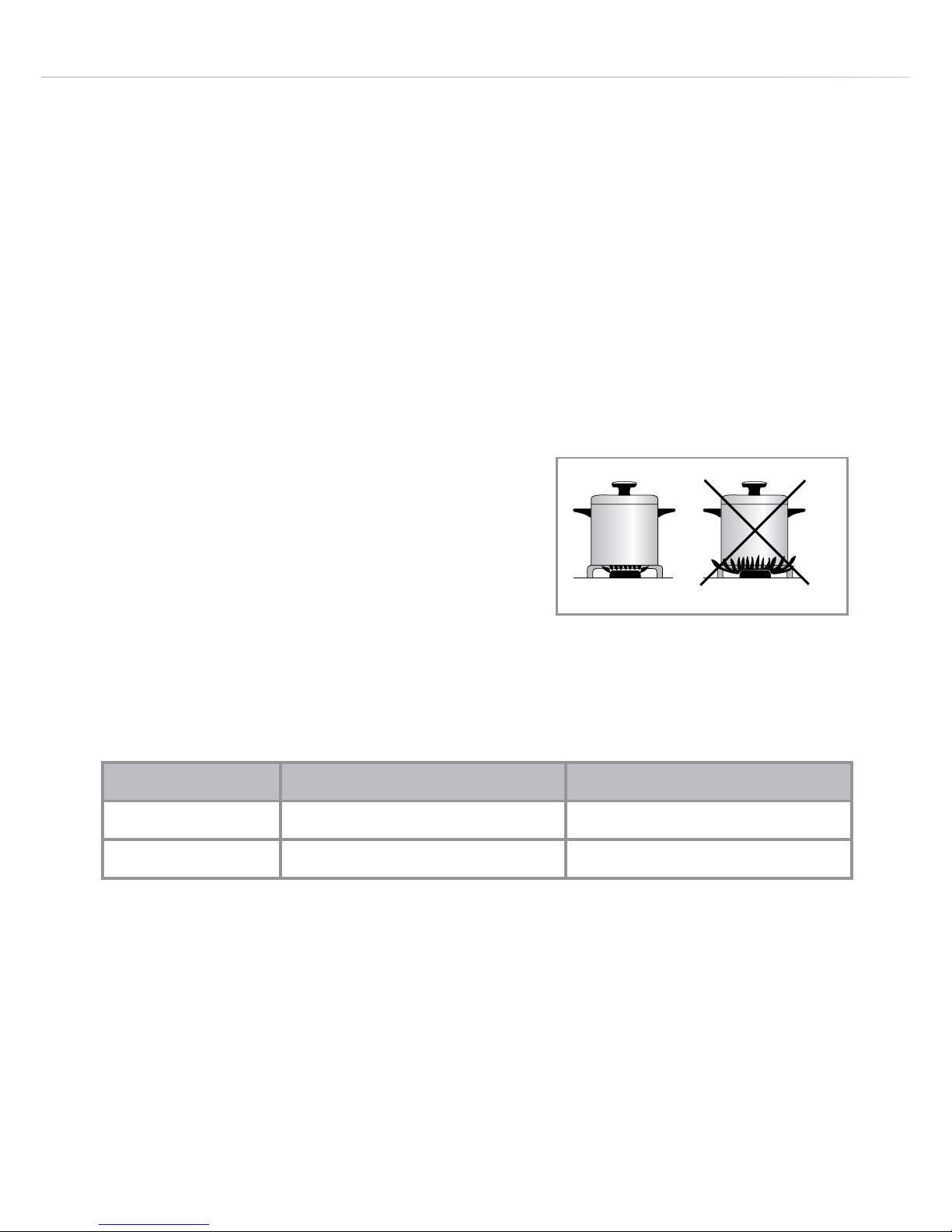
The most ecient use of the hob is shown below, where the pan and
burner are correctly chosen.
Ensure that the pans do not overlap the
edge of the pan stand, or cover the
control panel.
The table below shows the sizes of pan that should be used with each
pan support:
Fig. 3
Pan Support Minimum Pan Diameter (cm) Maximum Pan Diameter (cm)
Basic 22 30
Wok support - 36
Page 19
19
Correct Use of the Gas Burner
Burner mounting
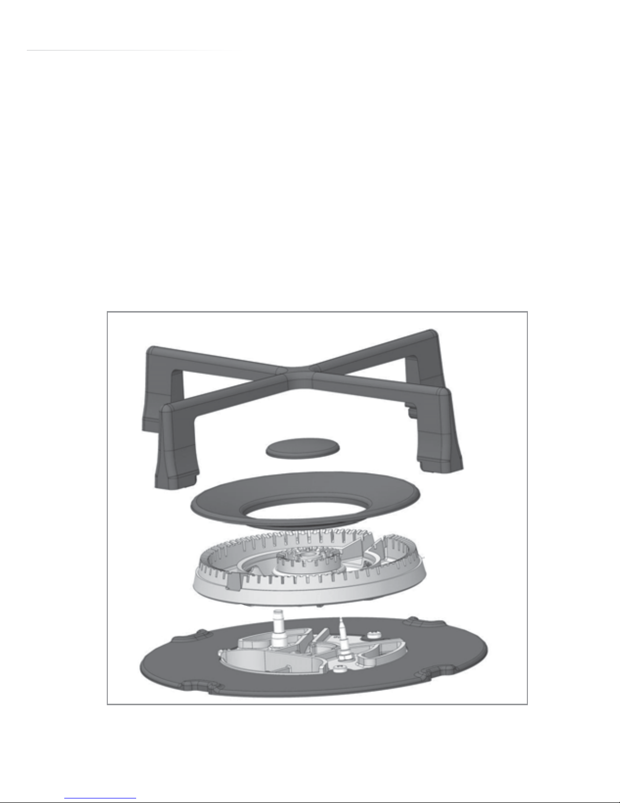
• It is essential to ensure that all the burner parts and pan supports
are properly assembled on the appliance to work correctly.
• A blue and stable flame shows that the burner is working properly.
• Do not remove burner caps during use.
• Mount all the parts of the burner as in Fig. 4 below.
SLFWXUH
Fig. 4
Page 20
20
Fig. 5
Safety system
• The burner is equipped with a safety system (thermocouple) and an
ignition system.
• The ignition starts automatically once a power level is selected for
the cooking zone.
• If the flame goes out accidentally the ignition will restart the burner.
• The ignition system should not be operated continuously for more
than 10 seconds.
• If the burner does not ignite, or turns o accidentally, switch the
burner to the “O” position and wait for one minute before attempting
to relight it.
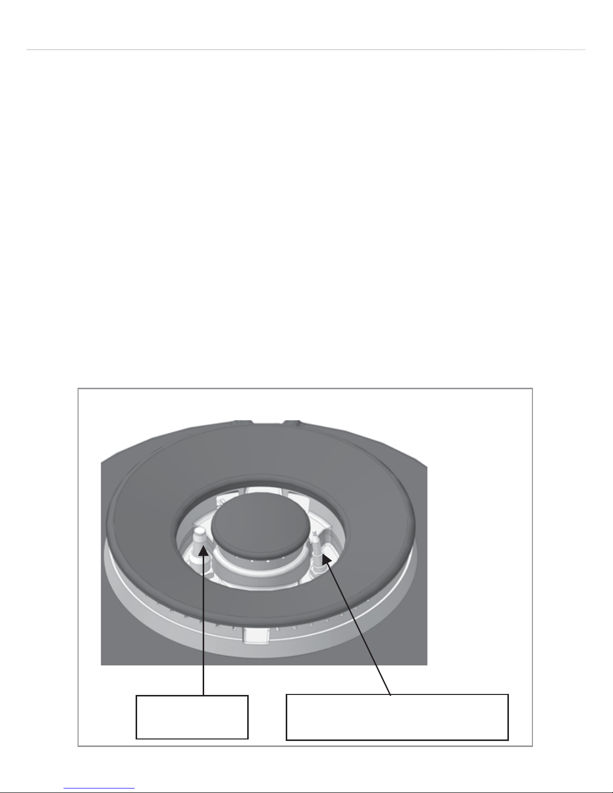
• The thermocouple and igniter must be kept very clean.
See Fig. 5 below.
,JQLWHU
7KHUPRFRXSOH
Page 21
21
Correct Use of the Wok Pan Adaptor
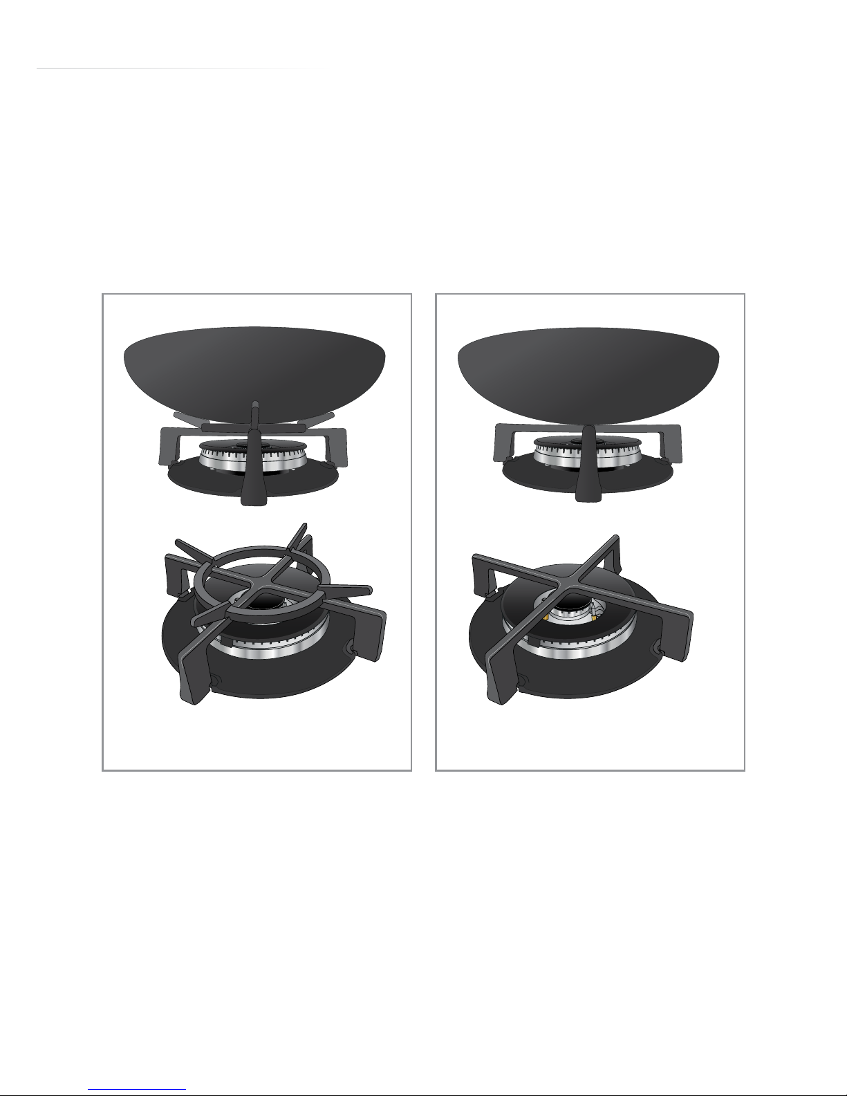
The wok pan adaptor is a special stand that is designed to be fitted
over the triple ring burner to give support to round bottomed woks.
When using a wok, always place the wok pan adaptor in position over
the pan support on the triple ring burner as shown in Fig. 6.
IMPORTANT:
• The wok pan adaptor (Fig. 6) must be placed over the pan support
on the triple ring burner.
• Do not use the wok pan adaptor for standard flat bottomed pans.
CORRECT
INCORRECT
Fig. 6 Fig. 7
Page 22
22
Care and Maintenance
Always disconnect the appliance from the power supply before
undertaking any cleaning or maintenance.
Important:
• Steam cleaners must not be used when cleaning this appliance. •
You should use a non-abrasive cleaner to clean the hob top. Any
abrasive cleaner (including Cif) will scratch the surface and
could erase the control panel markings.
• Sugar and starch can cause permanent damage to the surface of the
hob. Wipe away any spillages immediately.
If your hob is not working:
1. Check that the zone is switched on.
2. Check that the mains supply has not been switched o.
3. Check that the fuse in the spur has not blown.
Types of residues Clean with Cleaning advice
Light
Cleaning sponge and soft
cloth
Wipe over the zone to be cleaned with a
sponge and hot water, and then wipe o with a
soft dry cloth.
Accumulated baked-on
stains/dirt, sugar spills or
melted plastics
Cleaning sponge or glass
scraper and soft cloth
Wipe over the zone to be cleaned with a
sponge and hot water, using a ceramic scraper
to remove any large marks or stains and then
wipe o with a soft dry cloth.
Rings and hard water
residues
White vinegar and soft
cloth
Pour a small amount of warm white vinegar
onto the stain, leave it to stand, and then wipe
o with a soft dry cloth.
Shiny metallic streaks
Cleaning agent for
vitroceramic glass etc.
Use specialist vitroceramic glass cleaner
(preferably one with silicone for its protective
properties)
Page 23
23
Note: this hob is not suitable for conversion to LPG gas supply.
Burner Size Nominal Rating
(kW)
Simmer Rat-
ing
(kW)
G20/20mbar Natural Gas
Flow Rate (L/H)
Min Max
Triple / Wok 5.0 0.3 25 470
Page 24
24
Troubleshooting
On first use
On switching on
In use
You observe that Possible Causes What should you do?
Installation blows a fuse.
The electrical connection of the
hob is incorrect
Check that it is set up properly
(see the Electrical Connection
section)
You observe that Possible Causes What should you do?
The hob does not work and the
lights on the control panel do not
switch on.
Electrical connection fault. Check the power supply.
Protection circuit breaker or fuse
has tripped.
Replace the fuse or reset the
circuit breaker.
A small object, grease or water is
on one of the control keys.
Check the control keys are clean
and no objects are on them.
9
You observe that Possible Causes What should you do?
One or all of the zones cuts out.
The safety system has cut out.
Leave hob to cool then try it
again
A cooking zone has been
running for a very long time
Switch it on again (if required).
One or more control keys are
covered.
Clear any objects and clean
liquid from the control area.
A pan has boiled dry and is
overheating.
Remove the pan in question.
The fan continues to run after the
hob is switched o.
This is not a fault, the cooling
system is working correctly.
Nothing.
“U” flashes on the zone display.
The cookware used is not
suitable for induction.
See page 6 for information on
cooking on induction
There is no pan on the cooking
zone.
Place a suitable pan on the
cooking zone.
The bottom diameter of the pan
is too small.
Place a larger pan on the
cooking zone.
Page 25
25
You observe that Possible Causes What should you do?
“l l” shows on the displays.
The hob is in pause mode.
Refer to the section on “Pause
function” on pages 12-13.
“E” shows on the display.
The electronic system is
defective.
Contact CDA Customer Care for
advice.
“H” shows on a display. The zone is still hot to the touch.
Refer to the section on “Residual
heat indicators” on page 16.
“P” shows on a display.
The boost function is running on
the zone is .
Refer to the section on “Booster”
on page 13.
“Er03” shows on the zone
display.
One or more control keys are
covered
Clear any objects and clean
liquid from the control area.
“E2” shows on the display. The hob is overheated. Let it cool down, then try it again.
“E3” or “E7” shows on the
display.
An unsuitable pan is on the hob.
Remove the unsuitable pan
and only use pans suitable for
induction cooking.
“E4” or “EC” shows on the zone
Configuration error.
Contact CDA Customer Care for
advice.
“E6” shows on the display.
Defective power supply voltage
or frequency.
Contact CDA Customer Care for
advice.
“E8” shows on the display.
The ventilation air inlet is
blocked.
Clear the ventilation air inlet.
If Your Gas Wok Burner is Not Working
1. Check that the mains supply has not been switched o.
2. Check that the fuse in the spur has not blown.
3. Ensure that the burner components are not excessively soiled as
this can lead to ignition problems.
Page 26

26
Mains Electricity Connection
Warning! this appliance must be earthed
We recommend that the appliance is connected by a qualified
electrician, who is a member of the N.I.C.E.I.C. and who will comply
with the I.E.T. and local regulations.
This hob is intended to be connected to permanent fixed wiring by
a double pole switch, having a contact separation of at least 3mm in
all poles. The switch must be positioned no further than 2m from the
appliance.
Please note:
• The mains cable must only be replaced by a qualified electrician
or service engineer and must be of equivalent or better rating (i.e.
2.5mm2, HO5V2V2/F).
• This appliance is intended to be connected to the mains supply with
a cable of cross section area 2.5mm2. A larger cable will not fit the
terminal connections.
• The marking of the current rating of the fuse or circuit breaker
protecting this appliance should be marked on the socket outlet.
• Assembly and electrical connection should be carried out by
specialised personnel.
• When installing this product we recommend you seek the help of
another individual.
• Ensure that the brass links are securely fitted. Failure to do so will
prevent the hob from operating correctly.
• Protection against live parts must be ensured after installation.
• Connection data is printed on labels on the hob casing close to the
connection box.
Page 27
27
• As the appliance is not fitted with an accessible plug, a means of
disconnection from the power supply must be must be included in
the fixed installation, in accordance with the installation regulations.
• The inlet cable must be positioned so that it does not touch any of
the hot parts of the hob or oven.
Caution
• This appliance must only be connected to a 230V ~ 50Hz network.
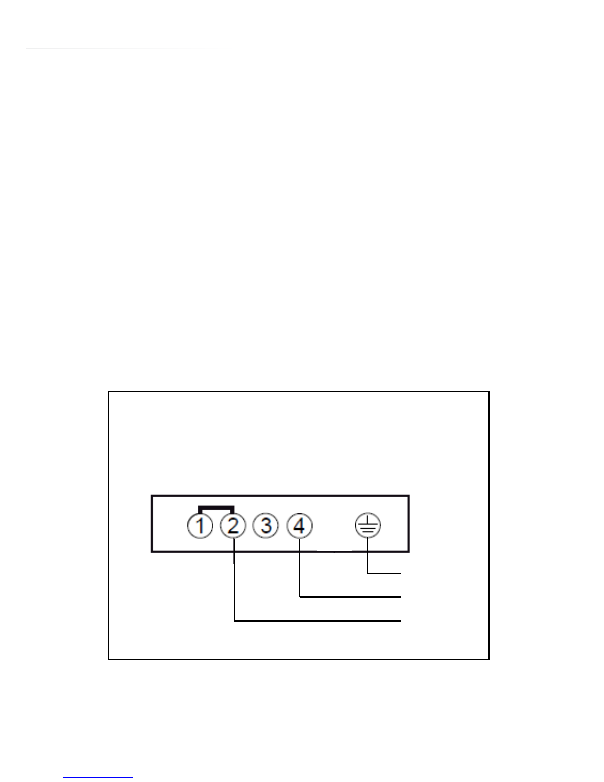
• Observe the connection diagram (below).
• The connection box is located underneath at the back of the hob
casing. To open the cover use a medium screwdriver. Insert it in the
slits to open the cover.
The following diagram shows the mains connection:
* Calculated using the diversity factor following the standard EN 60
335-2-6.
Fig.6
AC 220-240V 50/60Hz 25A*
E
N
L
Fig. 8
Page 28

28
Appliance electrical rating: 7.4kW
Total rated gas input: 5.0kW
Any service call arising from incorrect installation may result in a
charge.
CDA and its representatives cannot be held responsible for any
matters resulting from incorrect connection, or related to either the
absence of an earth connection or a faulty earth connection.
Gas Supply Requirements
IMPORTANT: THIS APPLIANCE SHOULD BE FITTED BY A GAS
SAFE REGISTERED FITTER OR OTHER SUITABLY QUALIFIED
PERSON.
• This installation must comply with the Gas Safety (installation and
use) Regulations 1984.
• This appliance is category I2H and is designed for use in GB & IE.
The installation must comply with the Gas Safety (installation and
use) Regulations 1984.
Page 29

29
• The CDA Group Ltd is not legally able to provide any assistance
in the installation of gas appliances except to Gas Safe registered
installers. Any Gas Safe registered fitter requiring help must provide
their name, address and registration number. Information supplied
will be validated before help is provided.
• In the event that this appliance is not installed in accordance with
the above requirements, the appliance may be disconnected
from the mains gas supply until any faults are rectified; this is a legal
requirement.
• This appliance shall be installed using 15mm copper pipe connected
via an isolation valve in an adjacent unit. The isolation valve needs
to be accessible in an emergency or for service purposes. All pipes
and connections shall comply with current legislative requirements.
• The gas connection shall be fitted in such a way that it cannot come
into contact with any moveable or hot part of the housing and does
not pass through any space where it may become crushed, kinked
or damaged in any way.
• Flexible gas hose(s) must not be used for connection of this hob.
• This appliance must not be connected to a combustion gas recovery
scavenging system
• The connection to the gas supply must comply with all current
regulations in force.
• We are not legally able to oer advice on the installation of gas
appliances to non Gas Safe registered personnel.
Page 30
30
Natural Gas to LPG Conversion
Due to the electronic gas control system fitted to this hob, it is not
possible to convert it from natural gas to LPG operation.
Ventilation
All rooms require a window or equivalent (e.g. a door) which can be
opened. Some rooms require a permanent vent in addition to a window (see below).
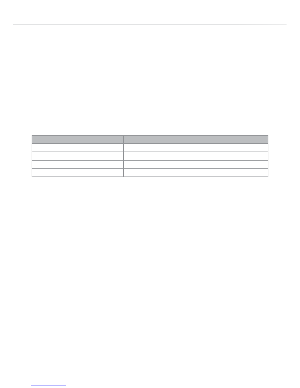
This unit must not be used in a room which is less than 5m3. The following table details the requirements based on the kitchen volume
(L x W x H) in m3.
The above requirements also allow use of a gas oven and grill but if
there are any other fuel burning appliances in the same room, consult
the relevant British Standard (BS5440) or GAS SAFE document.
Room Volume (m3)
5
6 to 10
6 to 11
11 or more
Air Vent Required (cm
2
)
100
50
No permanent vent required if a door opens to the outside
None required
Page 31

31
Fitting the Hob
Unpacking the hob:
Take care not to lose or mishandle any parts.
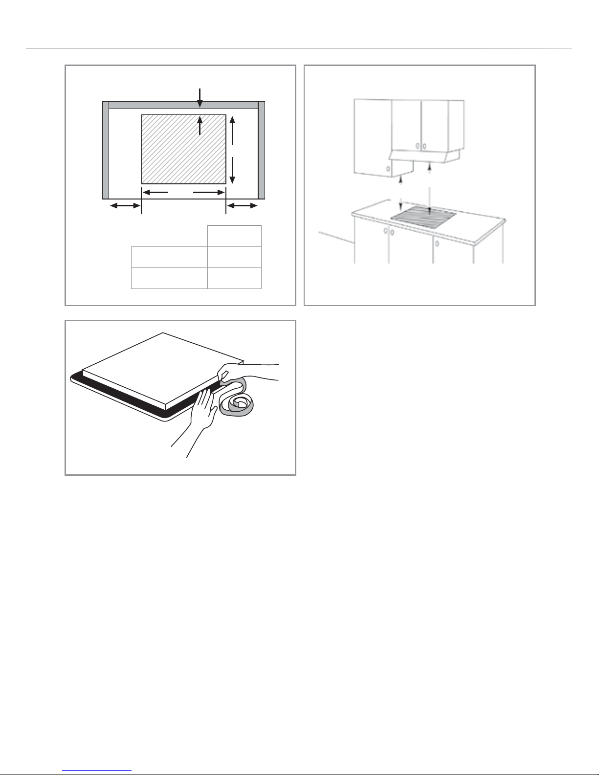
Fitting position of the hob:
This appliance must be installed a minimum of 50mm from any
back wall and a minimum of 150mm away from any adjacent vertical
surfaces, e.g. a tall cupboard end panel. This may be reduced to
100mm if the adjacent surface is resistant to fire (tiles or steel, for
example). These dimensions are shown in Fig. 8.
If fitting a cooker hood above the hob:
If a cooker hood is to be installed above the hob, the height of
the hood above the hob must be at least 760mm (Fig. 9). If the
instructions supplied with the hood dictate that the hood must be
installed at a height greater than 760mm, then that height is the
minimum required.
Wall furniture requirements:
The minimum height of any cabinet immediately above the hob is
900mm. The minimum height of any adjacent units (including light
pelmets) is 400mm, unless they are manufactured from a material
resistant to fire (steel, for example)
Notes:
• Do not position this appliance above a refrigeration unit. The heat
generated may cause the refrigeration unit to fail.
Page 32
32
• This appliance is designed to be installed into cabinet units capable of
withstanding temperatures 65°C above ambient or greater (typically
80-90°C).
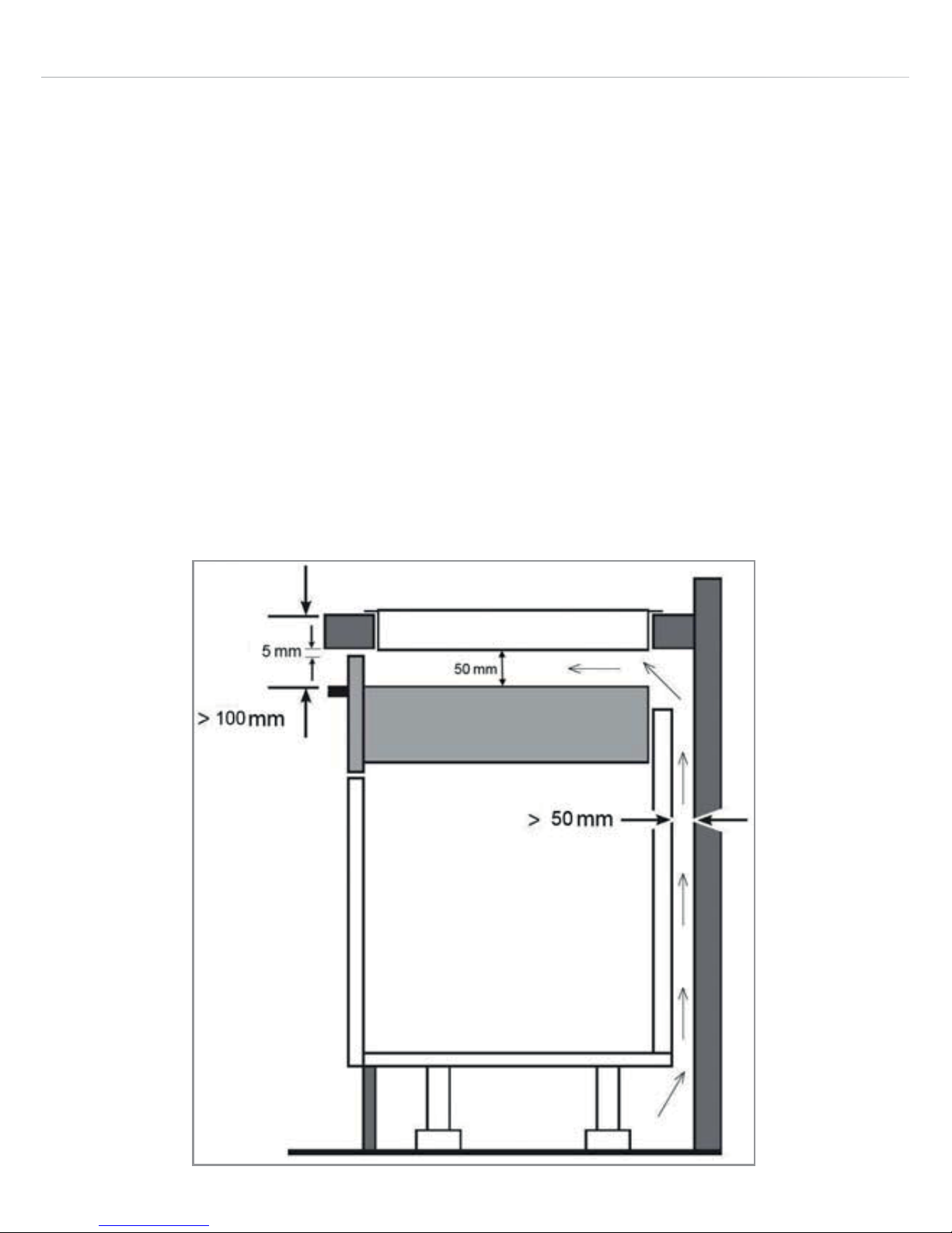
• If there is no oven to be built in below the hob it is recommended
that, an isolation shelf should be fitted to protect the user from high
temperatures. If the hob is to be installed above a working drawer,
then a partition should be fitted to protect the contents and user
from the heat generated during use. This should guarantee a space
of 50mm under the bottom of the hob casing to ensure a good
air circulation of the electronic devices. This panel should have a
ventilation space at the rear of greater than 50mm as shown in Fig. 9.
• Never place perishable foods in the cupboard below the appliance.
Fig. 9
Page 33
33
How to Install the Hob
1. Make the required hole in the worktop. Note that before doing this,
check the instructions supplied with any cooker hood to ensure that
you will have the required clearance. The cut-out (Fig. 10) shows a
65mm gap from the wall to the cut-out edge. The distance for
the hob, when fitted, to the back wall is 50mm.
2. Position the hob seal, as shown in the diagram below (Fig. 12),
ensuring that the ends meet without overlapping. Do not use silicone
type sealant.
When correctly installed, your product meets all safety
requirements laid down for this type of product. However, special
care should be taken around the rear or the underneath of the
appliance as these areas are not designed or intended to be
touched and may contain sharp or rough edges that could cause
injury.
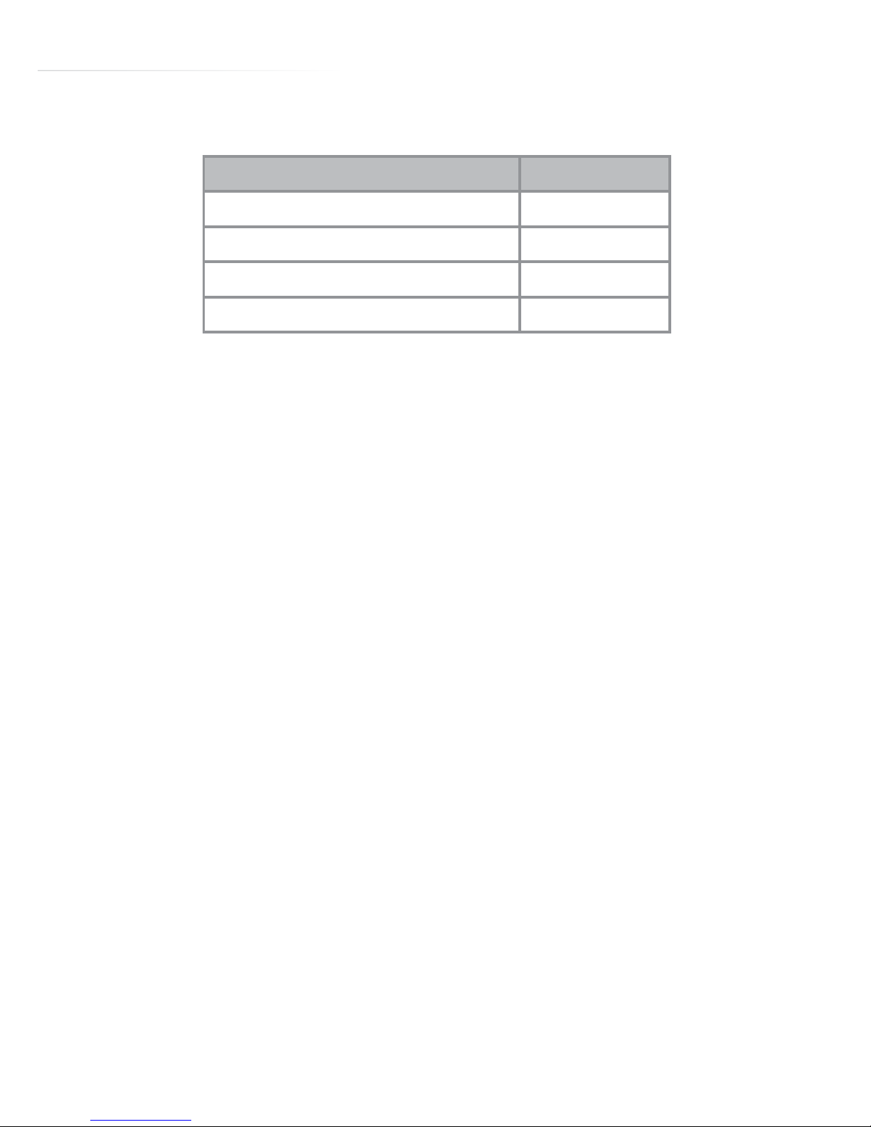
Installation Dimensions (mm) HNG7410
Overall width 780
Overall depth 520
Worktop cutout width 750
Worktop cutout depth 490
Page 34
34
m
Fig. 10
Fig. 11
Fig. 12
>65mm
L
L
W
490mm
HNG7410
Cutout width (W) 750mm
Landing (L) 165mm
750mm
400mm
Page 35

35
Energy Eciency Information
A) Measurement and calculation methods
• The gas hob was CE approval according to the Gas Appliance
Directives 2009/142/EC.
• The energy eciency of this gas hob was tested and measured
according to EN 30-2-1-1998+A1-2003+A2-2005.
• The energy eciency of the gas burners and the hob were
calculated according to COMMISSION REGULATION (EU) No.
66/2014.
B) Rational use of the energy and the appliance
• The gas hob is designed for domestic use only, please do not use
for commercial purposes.
• The gas hob is designed for use with gas (Natural gas), the
combustion products contain carbon monoxide and carbon dioxide,
the exhaust of combustion products is aecting our environment
when reaching a certain level of CO and CO
2
.
• To ensure the rational use of energy, please install the gas hob
according to the specifications in clause 5, and please make sure
you are using the correct diameter of pan for each burner.
• To ensure safe use, please read this instruction manual before use;
please follow the installation, operation and maintenance guideline.
Page 36
36
• To ensure the optimal life expectancy of the gas hob, please follow
the operation and maintenance guideline strictly; please do not
modify the appliance.
• Please contact your local after-sale service for repairing and
exchanging of the components (such as gas valve, control knob) if
necessary.
• The material of the gas hob is metal and glass, please dispose of
the gas hob in recycling when the gas hob comes to the end-of-life.
• The packaging materials of this appliance are recyclable, please
make good use of waste materials.
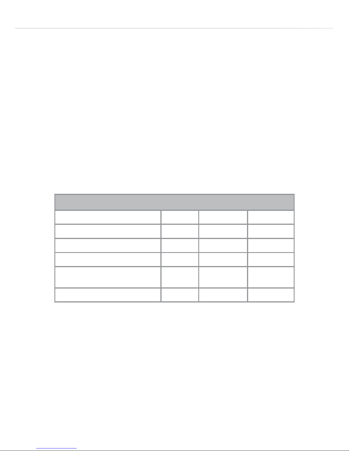
Energy Eciency Information - Gas Hob
Attribute Symbol Value Units
Model identification HNG7410FR
Type of hob Built in
Number of gas burners 1
Energy eciency per gas burner EE
Gas burner
Tr: 54.70 %
Energy eciency for the gas hob EE
Gas hob
54.7 %
Page 37
37
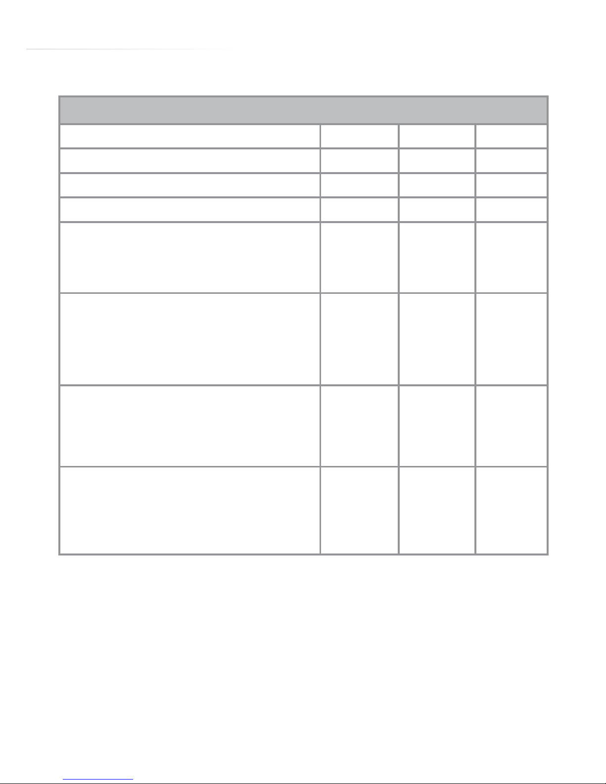
Energy Eciency Information - Electric Hob
Attribute Symbol Value Units
Model identification HNG7410FR
Type of hob Built in
Number of cooking zones and/or areas 4
Heating technology (induction cooking zones
and cooking areas, radiant cooking zones, solid
plates)
Induction
cooking
zones
For circular cooking zones or area: diameter of
useful surface area per electric heated cooking
zone, rounded to the nearest 5mm
Ø FL: 17.5 /
FR: 21.5 /
RL: 21.5 /
RR: 17.5
cm
For non-circular cooking zones or areas: length
and width of useful surface area per electric
heated cooking zone or area, rounded to the
nearest 5mm
L
W
NA cm
Energy consumption per cooking zone or area
calculated per kg
EC
electric cooking
FL: 177.3 /
FR: 168.4 /
RL: 178.0 /
RR: 177.3
Wh/kg
Page 38

38
NOTES:
Page 39

39
E & O E. All instructions, dimensions and illustrations are provided for guidance only. CDA reserve the
right to change specifications without prior notice.
NOTES:
Page 40
Customer Care Department • The Group Ltd. • Harby Road • Langar • Nottinghamshire • NG13 9HY
T : 01949 862 012 F : 01949 862 003 E : customer.care@cda.eu W : www.cda.eu
www.cda.eu
Customer Care Department • The Group Ltd. • Harby Road • Langar • Nottinghamshire • NG13 9HY
T : 01949 862 012 F : 01949 862 003 E : customer.care@cda.eu W : www.cda.eu
Please contact our Customer Care Department for Service on the details below
Customer Care Department
The Group Ltd. • Harby Road • Langar • Nottinghamshire • NG13 9HY
T : 01949 862 012 F : 01949 862 003 E : [email protected]
Copyright © CDA 2016
www.cda.eu
 Loading...