

Page 1

Customer Care Department • The Group Ltd. • Harby Road • Langar • Nottinghamshire • NG13 9HY
T : 01949 862 012 F : 01949 862 003 E : customer.care@cda.eu W : www.cda.eu
www.cda.eu
EVX101
Extractor
Installation, Use and Maintenance
Page 2

2
Important
The CDA Group Ltd cannot be held responsible for
injuries or losses caused by incorrect use or installation
of this product. Please note that CDA reserve the right to
invalidate the guarantee supplied with this product following
incorrect installation or misuse of the appliance or use in a
commercial environment.
This appliance is not designed to be used by people
(including children) with reduced physical, sensorial or
mental capacity, or who lack experience or knowledge
about it, unless they have had supervision or instructions on
how to use the appliance by someone who is responsible
for their safety.
Under no circumstances should any external covers be
removed for servicing or maintenance except by suitably
qualified personnel.
Appliance information:
Please enter the details on the appliance rating plate below for
reference, to assist CDA Customer Care in the event of a fault with
your appliance and to register your appliance for guarantee purposes.
Appliance Model
Serial Number
Page 3

3
CE Declarations of Conformity:
This appliance has been manufactured to the strictest standards and
complies with all applicable legislation, including Gas safety, Electrical
safety (LVD) and Electromagnetic interference compatibility (EMC).
IMPORTANT INFORMATION FOR CORRECT DISPOSAL OF THE
PRODUCT IN ACCORDANCE WITH EC DIRECTIVE 2002/96/EC.
At the end of its working life, the product must be taken to a special
local authority waste collection centre or to a dealer providing
appliance recycling services.
Disposing of a household appliance separately avoids possible
negative consequences for the environment and health. It also
enables the constituent materials to be recovered, saving both energy
and resources. As a reminder of the need to dispose of household
appliances separately, the product is marked with a crossed-out
wheeled dustbin.
Page 4

4
Please note:
• Under no circumstances should the extractor be
connected to any gas ventilation system, flue system or
hot air ducting system.
• Do not vent the extractor into an attic or loft space.
• Only house the extractor in rooms with adequate
ventilation. Remember that the extractor is powerful and
whatever air is extracted needs to be replaced.
• Do not tile the extractor in. It should be removable for
service or maintenance.
• Do not use silicone sealant to secure the hood to the wall.
• You must be able to isolate the extractor from the mains
electrical supply after installation.
• This extractor has been designed to be used in a room
with a volume of less than 36m.
• Steam cleaners must not be used when cleaning this
appliance.
• The performance of your extractor will vary depending
on a number of factors. These include: type of extraction,
length of ducting, room volume, ventilation available and
cleanliness of the filters.
Page 5
5
Using Your Extractor
For best performance, you should switch on the extractor 15 minutes
before starting to cook and leave it to run for approximately 15
minutes after the end of cooking.
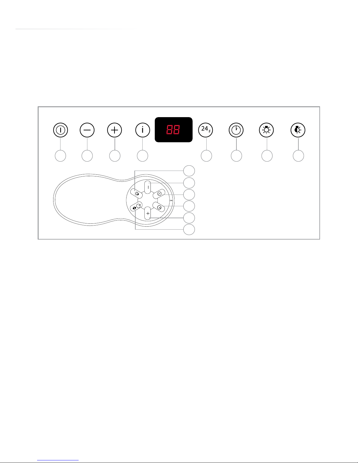
To switch on the extractor and set the speed level
- Touch key “A” or press button 1 on the remote. The appliance will
switch on at the last speed level used.
- To increase the speed level touch key “C” or button 2 on the remote.
- To reduce the speed level touch key “B” or button 4 on the remote.
The speed cycles through speed levels, and the relevant number
indicator will show on the display.
- To switch the extractor o, touch key “A” or button 1 on the remote.
The intensive function
The extractor is equipped with an intensive function which runs for ten
minutes before returning to the previous selected speed level.
- To activate the intensive function press key “D” or button 5 on the
fig. 1
HGA B C D FE
5
2
4
3
6
1
Page 6

6
remote control. Whilst the intensive function is active “HI” appears
on the centre of the display and the bottom right hand dot flashes
once a second.
- To cancel the intensive function, touch key “D” or button 5 again and
the extractor will return to the previous speed level.
The extractor lights
- To switch the lights on and o, press key “G” or button 6 on the
remote control.
The extractor is equipped with an ambient light function, which dims
the lights. To activate the ambient light function, press key “H” or
press and hold button 6 on the remote control for three seconds.
The timer
The extractor is equipped with a timer that allows the extractor to run
for 30 minutes before switching o automatically.
- To activate the timer, touch key “F” or press button 1 on the remote.
The working speed and time remaining will flash alternative on the
display and a dot will flash in the lower right hand corner of the
display.
- To cancel the timer, touch key “F” or button 1 on the remote control.
Please note
The timer cannot be activated when the intensive function is on.
The clean air function
- The extractor is equipped with a clean air function that runs the
motor for 10 minutes every hour at 100m/h to keep the air in the
kitchen refreshed.
Page 7

7
- To activate the clean air function, touch key “E” when the appliance
is either on or o. When the clean air function is running, “24” will
show on the display and a dot will flash in the lower right hand
corner of the display when the motor is running.
- To cancel the clean air function, touch any key except the light key.
Care and Maintenance
IMPORTANT : DO NOT PERFORM MAINTENANCE OR ATTEMPT
TO CLEAN THE EXTRACTOR WITHOUT FIRST SWITCHING OFF
THE ELECTRICITY SUPPLY.
Cleaning
You should use a nonabrasive cleaner. Any abrasive cleaner (including
Cif) will scratch the surface and could erase the control panel
markings.
You can clean your extractor eectively by simply using a dilute
solution of water and mild detergent and drying to a shine with a
clean cloth.
Cleaning the grease filters
The grease filters should be kept clean to minimise the risk of fire.
After 100 hours of use, “FF” will show on the display when the
extractor is switched o. This indicates that you should remove and
clean the grease filters with hot soapy water. You can also wash
the grease filters in a dishwasher, ensuring that you place them
in an upright position to prevent damage from other items in the
dishwasher. After rinsing and drying, replace the filters.
Page 8
8
To reset the filter alarm, press button “E”
for approximately 3 seconds when the
extractor is switched o.
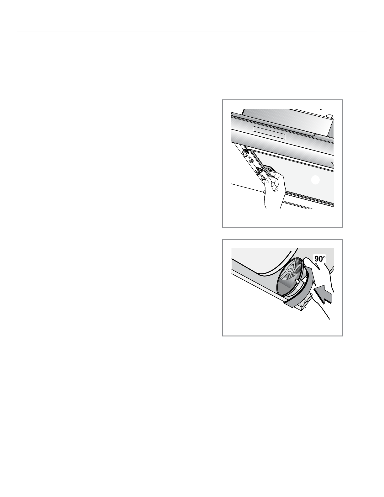
To remove the grease filters follow the
steps below:
1. Open the stainless steel cover panels
by pulling them down and outwards
on either side. They will remain
located in their hinges.
2. Pull open the handle on each grease
filter as shown in fig. 3. It will release
at the handle side. Then lower the
grease filter to remove it completely.
To replace the grease filters, repeat the
above steps in reverse.
Please note:
Cleaning the grease filters in the
dishwasher may lead to discolouration.
This is normal and does not constitute a
fault with the appliance.
Changing the charcoal filter
(re-circulating only)
After 200 hours of use “EF” will show
on the display when the extractor is
switched o. This indicates that you
fig. 2
fig. 3
Page 9
9
should remove and replace the charcoal filters.
To attach a new charcoal filter, first open the cover panels and remove
the grease filters as described above. Then oer up the charcoal
filter to the side of the motor as shown in figure 3 and turn it clockwise
until it locks into place. Repeat with the other charcoal filter on the
other side of the motor. Then replace the grease filters and cover
panels.
To reset the filter alarms, press button “E” for approximately 3 seconds
when the extractor is switched o.
Care and Maintenance
IMPORTANT: DO NOT PERFORM
MAINTENANCE OR CLEANING OF
THE EXTRACTOR WITHOUT FIRST
SWITCHING OFF THE ELECTRICITY
SUPPLY.
DO NOT CHANGE THE LIGHT BULB
IMMEDIATELY AFTER USE AS THE
BULB WILL BE HOT. ALLOW IT TO
COOL BEFORE REMOVING IT.
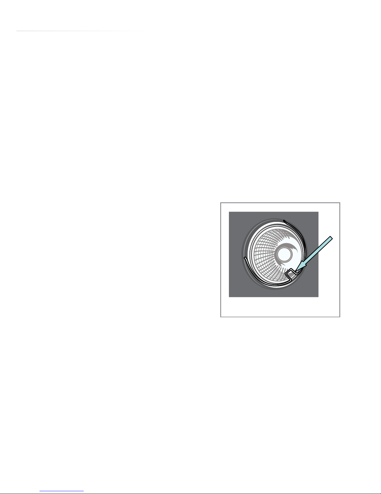
Carefully remove the lamp securing
spring using a set of long-nose pliers or
a small screwdriver as shown in fig. 4,
and the bulb will be released.
fig. 4
Page 10
10
Remove the old bulb from the holder.
Fit the new bulb, taking care not to touch the glass of the bulb.
Take care to ensure any tools used do not damage the extractor
body.
Do not touch bulbs or adjacent areas during or straight after
prolonged use of the lights.
The main extractor light is designed for use during cooking only.
Extended use of the extractor light can reduce the life span of the
bulb.
Bulb replacement is not covered by the guarantee.
Only use bulbs recommended for your extractor. Do not fit bulbs of a
higher power rating.
Bulbs of a lower power rating may be adequate for use, generally last
longer and use less energy.
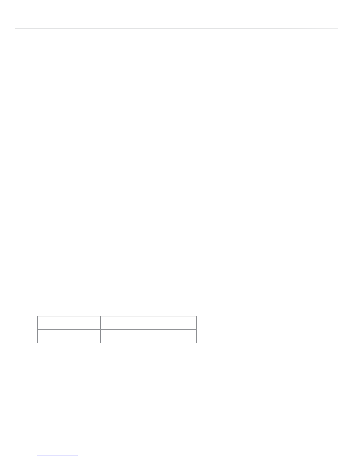
Model Light Bulbs Required
EVX101 GU10 4 x 4W LED
Page 11
11
Installation
Positioning the vent outlet:
The motor unit can be turned to
position the outlet to any of the four
sides.
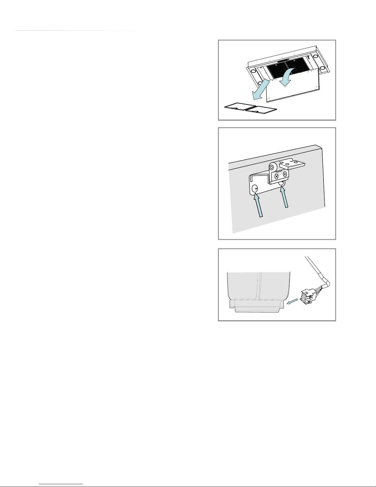
1. Open the decorative cover panel and
remove the two grease filters (fig. 5).
The decorative cover can be removed,
if required, to make the installation
easier. To do this, simply remove the
cover fixing screws using an allen key
or suitable hex driver (3mm), as shown
in figure 6: Lift the panel away, placing
it on a soft surface for safe storage.
2. Turn the appliance on its back and
disconnect the cable connector from
the motor housing, as shown in figure 7.
3. Using an 8mm spanner or socket, remove the four screws securing
the motor unit to the body and unhook the cable from the plastic
location clip so that the motor is free of the main body.
4. Rotate the body through 90⁰, 180⁰ or 270⁰ and refit the four
securing screws.
fig. 5
fig. 6
fig. 7
Page 12
12
Installation
Installing the extractor:
The extractor can be mounted directly
into the ceiling, where space between
the ceiling and joists permits, or it can
be built into a false ceiling. To install
the product, proceed as follows:
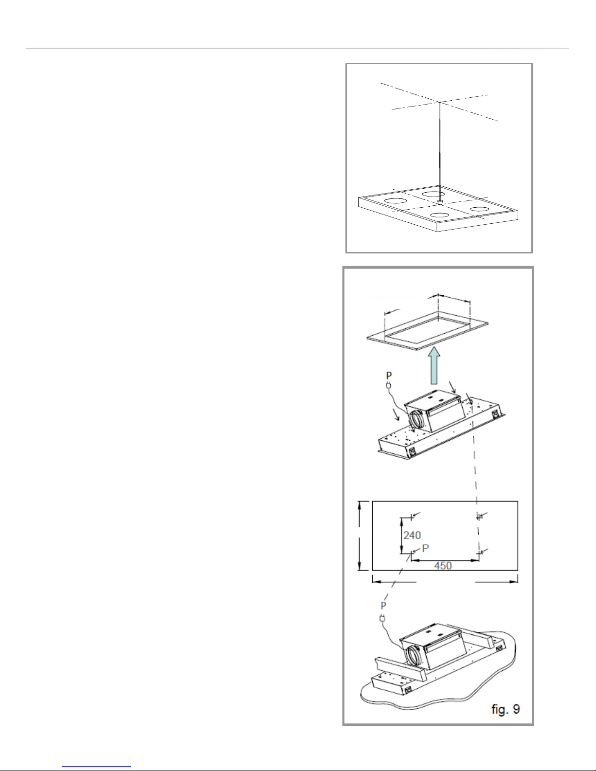
1. Mark the ceiling or false ceiling, as
appropriate, with centre point of the
hob to start the positioning of the
extractor, as shown:
Fixing Using the Motor
Structure:
(Two persons required)
2. Cut the mounting aperture for the
main body of the extractor, using the
dimensions shown in fig 9.
3. Mark the support holes in the ceiling
where the fixing screws and mains
cable will be located, as shown in
fig 9.
fig. 8
fig. 9
960 mm
460 mm
960
460
Page 13
13
4. Drill the dierent holes required for
the mounting, as below, using a drill
bit suitable for the ceiling material:
• The 150mm diameter vent outlet
when the ducting will run through the
ceiling.
• The mains supply chord (10mm
minimum).
• The four fixing holes for the 10mm
nuts and bolts.
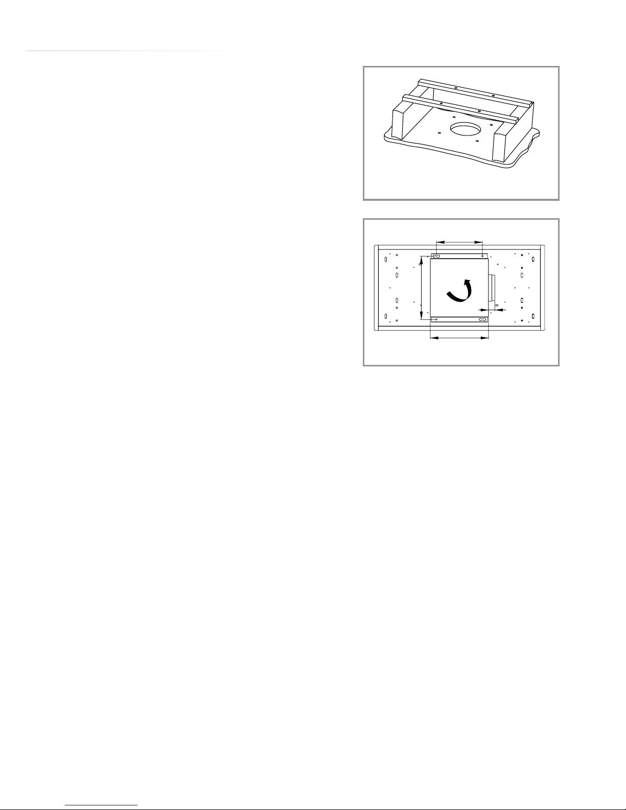
5. When the extractor is to be mounted
into a plasterboard ceiling additional
supports are required to carry
the weight of the extractor. The
example on the right shows suitable
reinforcement batons for use with
plasterboard ceilings:
Do not rely on the plasterboard ceiling
alone to carry the weight of the product.
The dimensions of the motor and its
support fixings are shown below:
Secure the extractor in position. When
fixing the extractor to a plasterboard
fig. 10
371.5
270
342
36
0°
fig. 11
90⁰, 180⁰
or 270⁰
Page 14
14
ceiling, use a sleeve to prevent damage
to the plasterboard when the four 10mm
nuts and bolts are being tightened.
When the ceiling is concrete, use eight
diameter symbol 10mm steel rawl bolts.
Do not use plastic rawl plugs
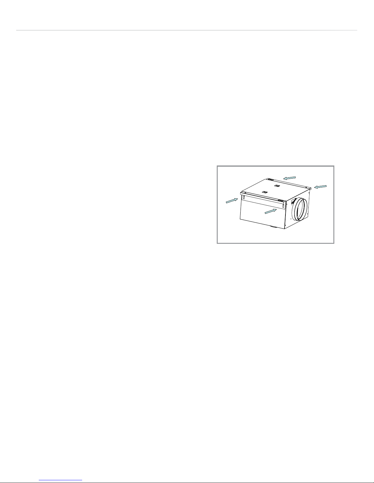
6. The motor body incorporates top
fixing mounts that can be adjusted
by up to 20mm depending on the
installation, as shown opposite.
Slacken the four screws shown and
position the fixing mounts to the
correct position, then re-tighten the
screws.
7. Before securing the extractor to the
ceiling, prepare and connect the
ducting as described in the ducting
section following the installation
information and ensure that the mains
electrical supply to the extractor
is connected, as described in the
electrical connection section.
fig. 12
Page 15
15
Installation Into a
False Ceiling:
(Two persons required)
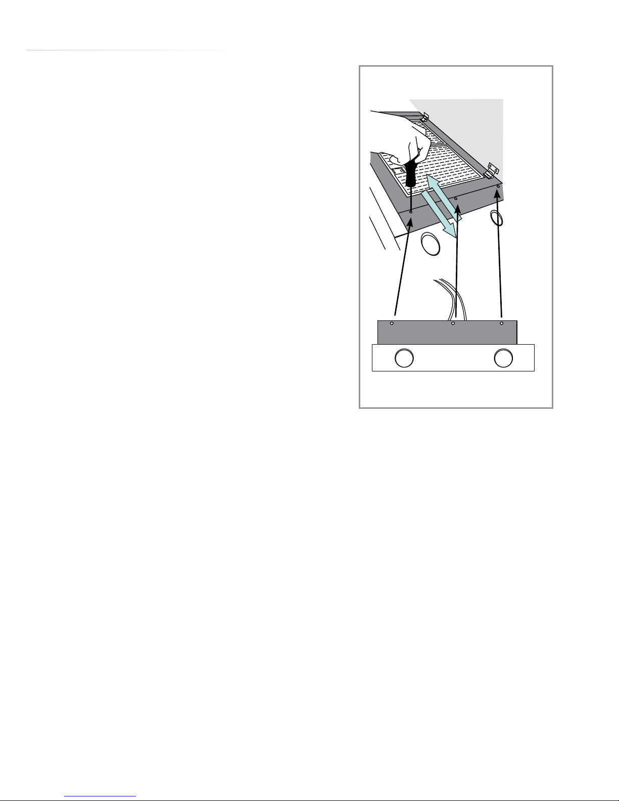
1. Open the decorative cover panel and
remove the two grease filters.
2. Remove the light panels by removing
the three screws securing each panel
first. Lift the panel and pull towards
the centre of the extractor to expose
the connections.
Carefully disconnect the light
connections and place the panels on a
soft surface to protect the steel finish.
The decorative cover can be removed,
if required, to make the installation
easier. To do this, simply remove the
hinge fixing screws then lift the panel
away, placing it on a soft surface for
safe storage.
fig. 13
Page 16
16
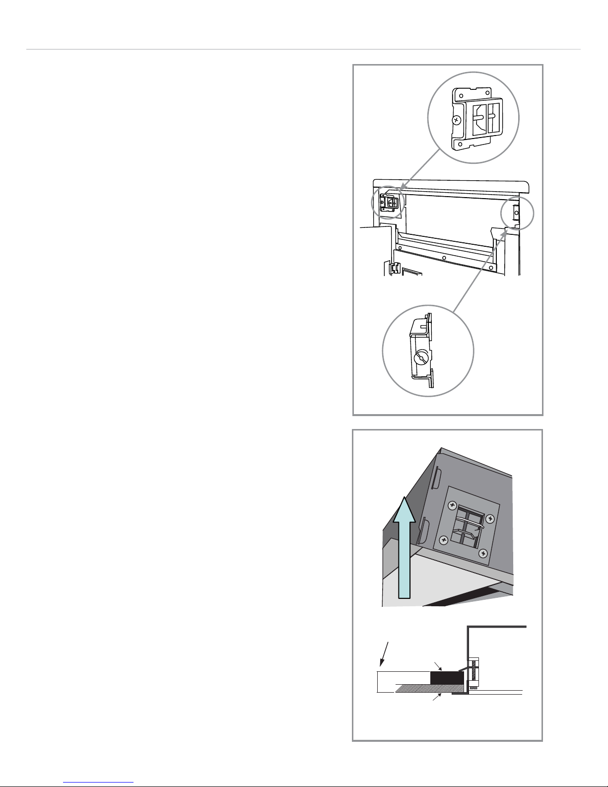
fig. 15
3. The extractor is intended to be
secured to the ceiling using the four
adjustable spring-loaded clips; these
are shown in the image below:
4. Before securing the extractor to the
ceiling, prepare and connect the
ducting as described in the ducting
section following the installation
information and ensure that the mains
electrical supply to the extractor
is connected, as described in the
electrical connection section.
5. The extractor is designed to be fitted
into a reinforcement frame fitted to
the false ceiling, as shown:
Prepare the ceiling before securing the
extractor in position.
Important:
Connect the mains power lead and
ventilation duct before locating the
extractor.
Tighten the securing clips using
fig. 14
Min. 20 mm
Max. 35 mm
False ceiling (plaster)
Frame - Reinforcement
Page 17
17
the adjustment screw to secure the
extractor firmly in position
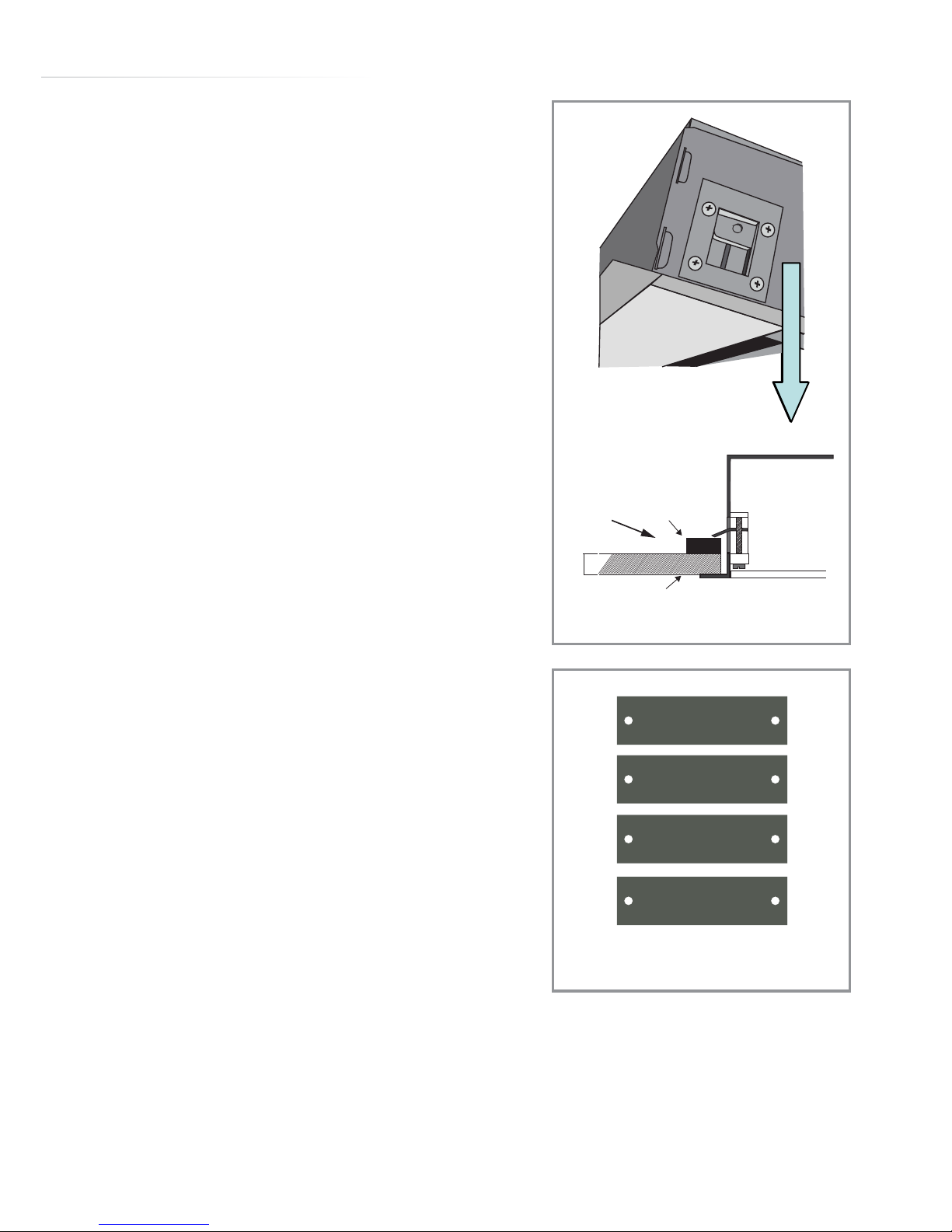
Note:
When fixing to an 18mm MDF false
ceiling, four 2mm spacers have been
provided to make the mounts 20mm
thick (minimum).
If the extractor needs to be removed
after installation for any reason, the
fixing clips should be slackened and
then can be accessed by removing
the foil covering. Push them to fold
them into line with the body. Take care
and get assistance when doing this to
prevent the risk of injury caused by the
extractor falling from the ceiling.
6. Re-connect the light terminals
and light panels to complete the
installation. If the decorative cover
panel was removed then refit this
also.
fig. 16
False ceiling (MDF)
18 mm
Spacer
fig. 17
2mm
Page 18

18
Ducting:
The extractor can be used as a recirculation device or as a extraction
device, depending on your installation.
The hood is more eective when used in the extraction mode (ducted
to the outside). When the cooker hood is ducted to the outside,
charcoal filters are not required. The ducting used must be 150mm
(6 Inches), rigid circular pipe and must be manufactured from fire
retardant material, produced to BS.476 or DIN 4102-B1.
Wherever possible utilise rigid circular pipe which has a smooth
interior, rather than the expanding concertina type ducting. The
maximum length of the ducting without performance being aected is
as follows:
• 4 metres with 1 x 90° bend.
• 3 metres with 2 x 90° bends.
• 2 metres with 3 x 90° bends.
Longer ducting can be used but the performance of the extractor will
be reduced.
Please note ducting components and ducting kits are optional
accessories and have to be ordered, they are not automatically
supplied with the hood. Use of ducting less than 150mm in diameter
will aect performance and increase the noise produced by the
extractor.
Page 19
19
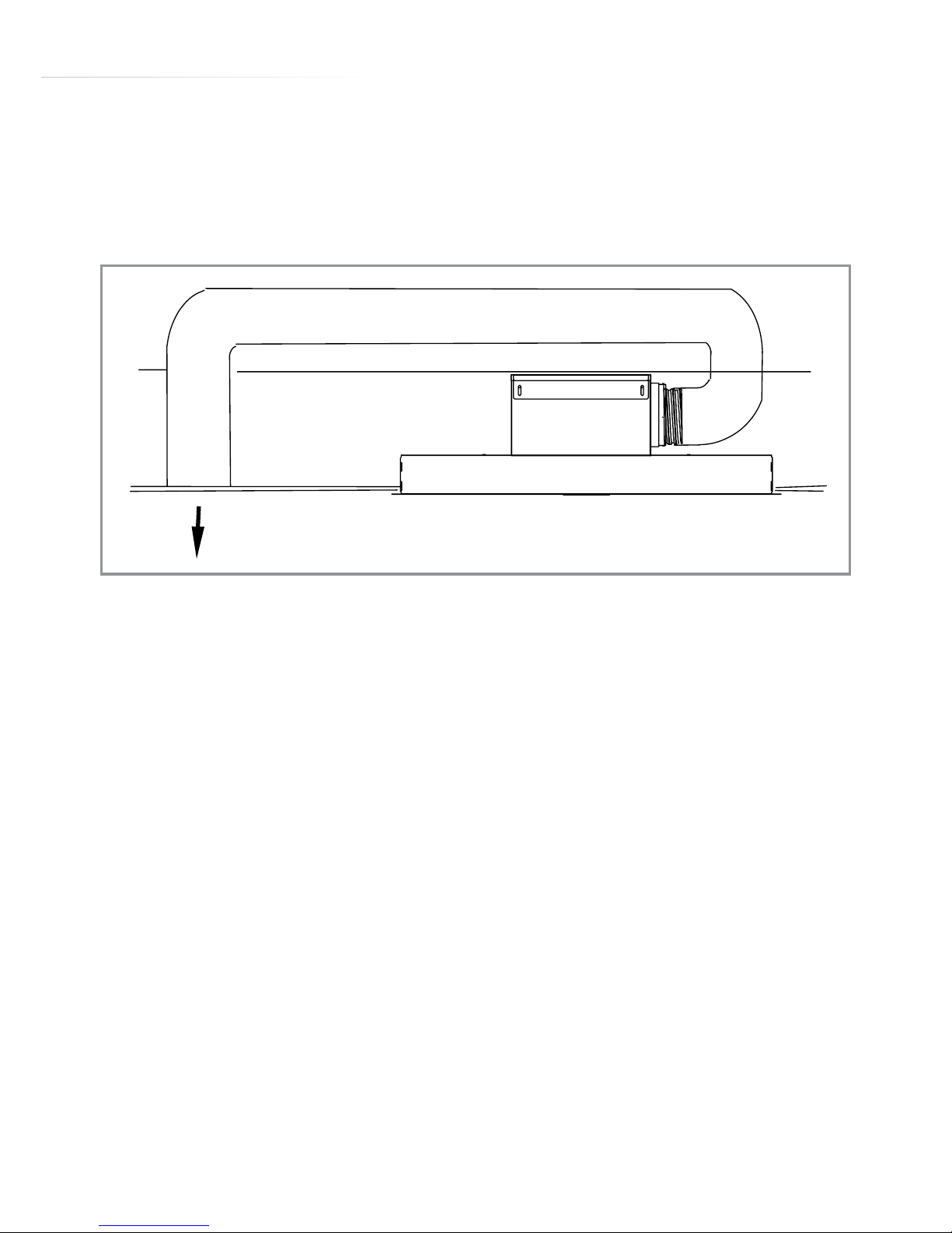
Re-Circulation:
An internal air vent is required, as shown below. This ensures that the
air is placed back in the kitchen after it has been filtered
Fit the charcoal filters to the body of the motor as shown in the
maintenance section of the manual.
Extraction:
The extractor is provided with a non-return butterfly valve which
should be fitted over the vent outlet before the ducting is fitted. This
prevents cold air being blown into the room from outside.
Securing the Duct to the Outlet:
Note that the duct pipe should be secured and sealed to the vent
outlet pipe / valve using appropriate ducting tape or a securing clamp.
fig. 18
Page 20
20
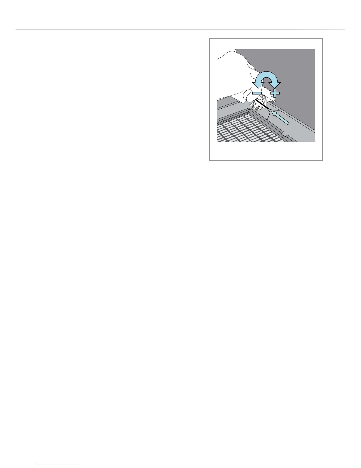
Adjusting the Position
of the Decorative
Cover Panel:
The decorative panel can be finely
adjusted by moving the positions of
the cover hinges, as shown here. Use
a suitable allen key or small hex driver
(3mm) to slacken the cover adjusting
screws before sliding the cover into the
correct position. When done, re-tighten
the fixing screws.
fig. 19
Page 21
21
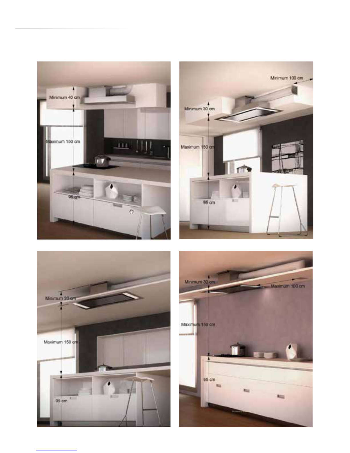
Typical Installation Examples:
Page 22

22
Changing the Light
IMPORTANT: DO NOT PERFORM MAINTENANCE OR ATTEMPT
TO CLEAN THE EXTRACTOR WITHOUT FIRST SWITCHING OFF
THE ELECTRICITY SUPPLY.
Synchronising the remote control with the extractor
When the extractor is o, press and hold button “B”, and then switch
the extractor on.
After five seconds release button “B” and the display will light up in
sections. Then press button “E”.
“TC” will flash twice to confirm the remote is synchronised.
“TC” will flash once to confirm the remote is not synchronised.
To change the battery
The remote control is powered by two standard LR03-AAA batteries.
To open the battery compartment, slide the rear panel down and then
lift the panel.
To replace the rear panel, locate the panel over the battery
compartment then slide the panel up until it clicks.
Page 23
23
Mains Electricity Connection
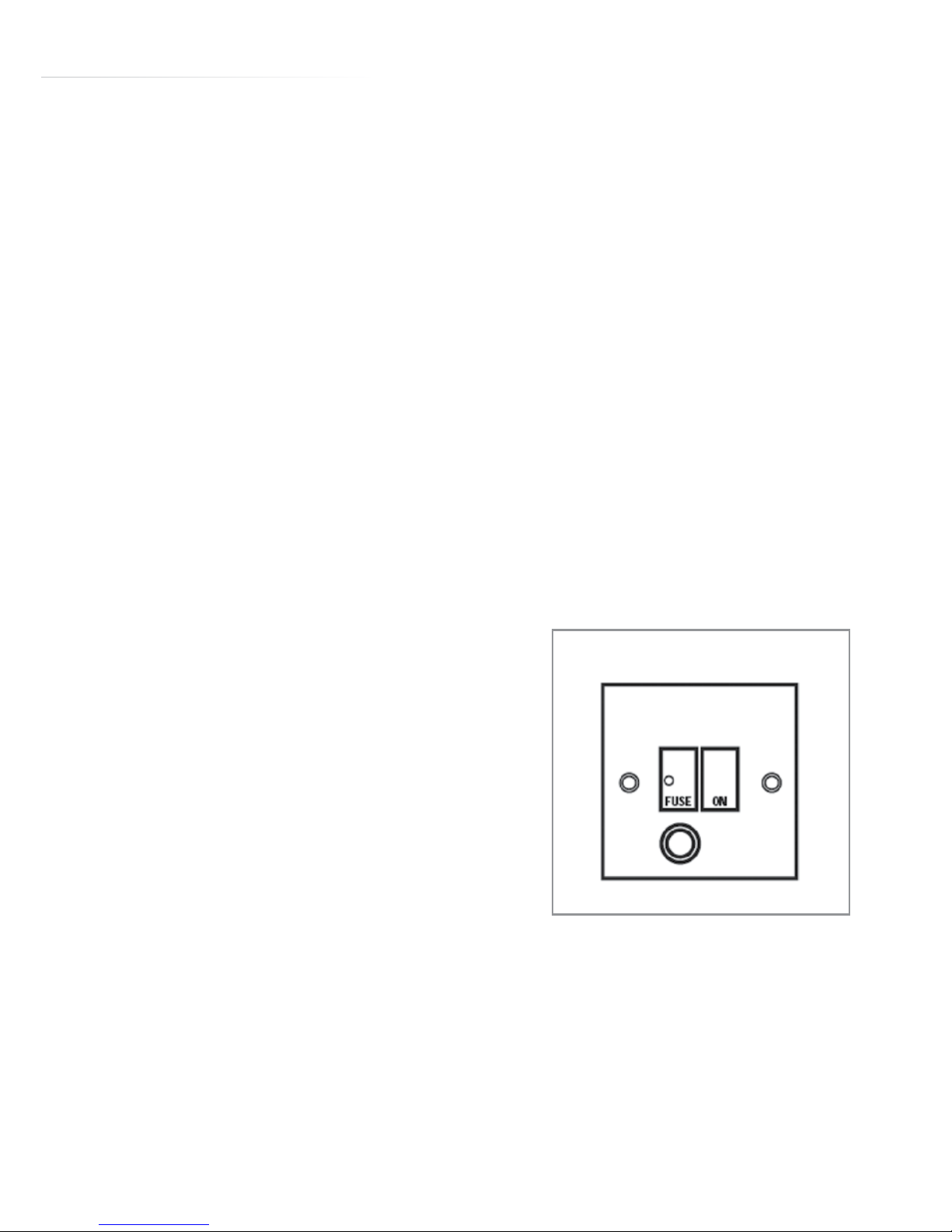
THIS APPLIANCE MUST BE CONNECTED TO THE MAINS SUPPLY BY
A COMPETENT PERSON, USING FIXED WIRING VIA A DOUBLE POLE
SWITCHED FUSE SPUR OUTLET AND PROTECTED BY A 3A FUSE.
Warning! This appliance must be earthed
We recommend that the appliance is connected by a qualified
electrician, who is a member of the N.I.C.E.I.C. and who will comply
with the I.E.T. and local regulations.
The wires in the mains lead of this appliance are coloured in
accordance with the following code:
Green & Yellow = Earth, Blue = Neutral, Brown = Live.
As the colours of the wires in the
mains lead for the appliance may not
correspond with the coloured markings
identifying the terminals connecting to
the fuse spur, proceed as follows:
• The wire which is coloured green and
yellow must be connected to the
terminal marked E (Earth) or coloured
green.
• The wire which is coloured blue must
be connected to the terminal
marked N (Neutral) or coloured black.
DOUBLE POLE SWITCHED
FUSE SPUR OUTLET
USE A 3 AMP FUSE
Page 24

24
• The wire which is coloured brown must be connected to the
terminal marked L (Live) or coloured red.
Note: Use a 3A Fuse
Assembly and electrical connection should be carried out by
specialised personnel.
When installing this product we recommend you seek the help of
another individual.
The mains isolation switch should be readily accessible after the
appliance has been installed and it is recommended that the isolation
switch is located within 2m of the appliance, where practical.
This appliance is intended to be connected to the mains electrical
supply by means of an isolation switch and fused spur and is intended
to be protected by a 3A fuse. The use of a 13A fuse can cause
damage to the internal wiring in the event of a fault, and may also
invalidate the warranty.
Page 25

25
Electrical Information
Mains electrical voltage: 230 – 240Vac
Total rated power consumption: 286W
Troubleshooting
Please note:
Your extractor is equipped with a motor protection device that will
switch o the motor to prevent damage from overheating.
This may happen during cooking when most or all of the zones/
burners are being used simultaneously.
This is normal, and the extractor will work again once the motor has
cooled suciently.
If your extractor is not working:
1. Check that the mains supply has not been switched o.
2. Check that the fuse in the spur has not blown.
Contact CDA Customer Care
A : Customer Care Department, The CDA Group Ltd, Harby Road,
Langar, Nottinghamshire, NG13 9HY
T : 01949 862 012
F : 01949 862 003
E : [email protected]
W : www.cda.eu
Page 26

26
Page 27
27
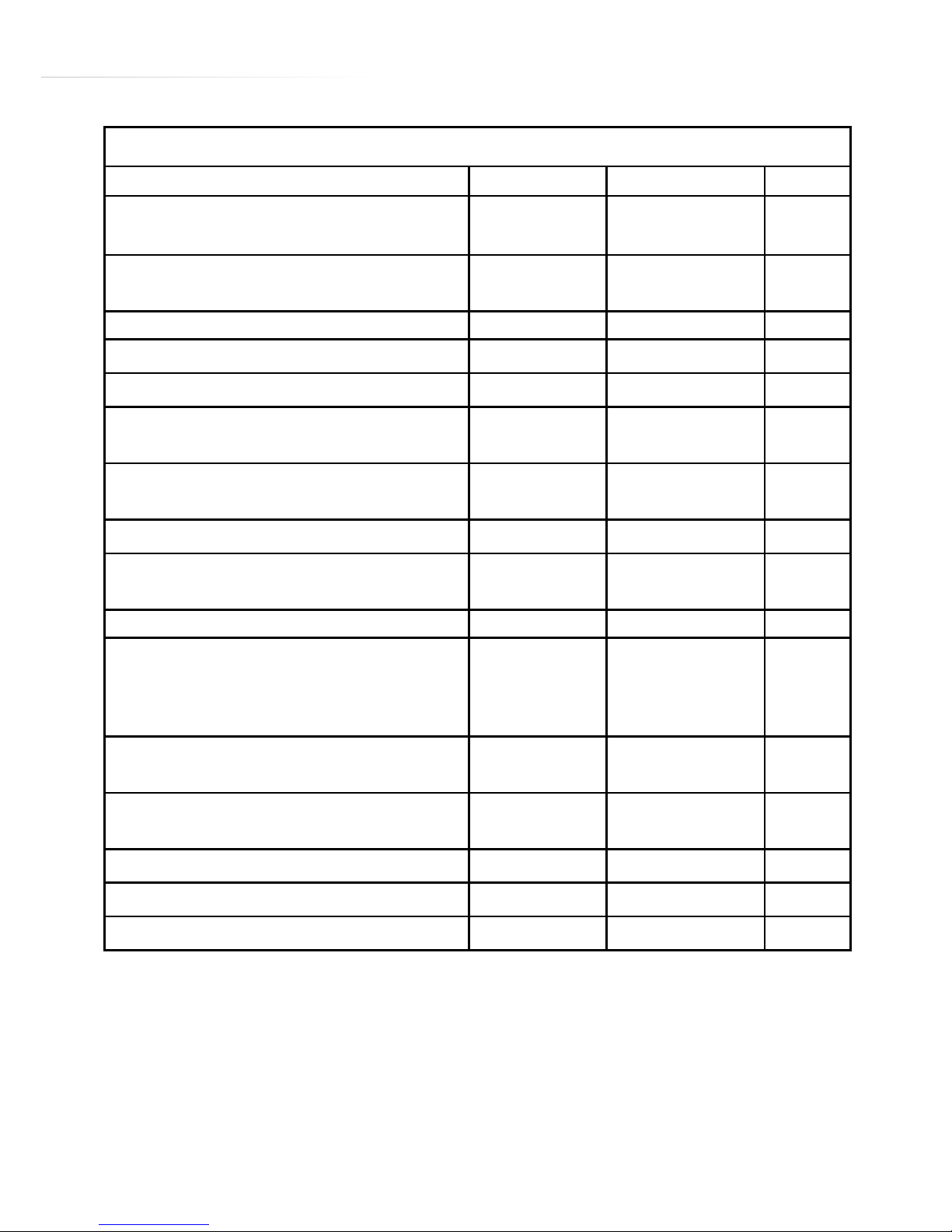
Attribute Symbol Value Units
Model Identification EVX101
Annual Energy Consumption AEC
Hood
67.6 kWh
Time increase factor f 1.0
Fluid Dynamic Efficiency FDE
Hood
28.4 (A)
Energy Efficiency Index EEI
Hood
61.1
Measured airflow at Best
Efficiency Point
Q
BEP
375
m
3
/h
Measured Pressure at Best
Efficiency Point
P
BEP
430 Pa
Maximum airflow Q
MAX
570
m
3
/h
Measured electric power at
Best Efficiency Point
W
BEP
158 W
Nominal lighting power WL 15.2 W
Average illumination of the
lighting system on the
cooking surface
E
Middle
545 Lux
Measured power consumption
in standby
P
S
NA W
Measured power consumption
off mode
P
O
0.7 W
Sound power level L
WA
59 dBA
Grease Filter Efficiency GFE
Hood
66.0 (D) %
Lamp efficiency LE
Hood
35.9 (F) %
Energy Efficiency Information
E & O E. All instructions, dimensions and illustrations are provided for guidance only. CDA reserve the
right to change specifications without prior notice.
Page 28
Customer Care Department • The Group Ltd. • Harby Road • Langar • Nottinghamshire • NG13 9HY
T : 01949 862 012 F : 01949 862 003 E : customer.care@cda.eu W : www.cda.eu
www.cda.eu
Customer Care Department • The Group Ltd. • Harby Road • Langar • Nottinghamshire • NG13 9HY
T : 01949 862 012 F : 01949 862 003 E : customer.care@cda.eu W : www.cda.eu
www.cda.eu
Please contact our Customer Care Department for Service on the details below
Customer Care Department
The Group Ltd. • Harby Road • Langar • Nottinghamshire • NG13 9HY
T : 01949 862 012 F : 01949 862 003 E : [email protected]
Copyright © CDA 2015
 Loading...