

Page 1

www.cda.eu
EVCK41
Cylinder Extractor
Installation, use and maintenance
Page 2

2
Contents:
3 Important
4 Important information
6 Using your extractor
7 Timer function
7 Clean air function
8 Care and maintenance
8 Removing the grease filter
9 Changing/fitting the charcoal filter(s)
10 Changing the light
11 - 15 Installation
11 Installation preparation - height
13 Ducting and ventilation
14 Mounting the extractor
16 Mains electricity connection
17 Electrical information
17 - 18 Troubleshooting
19 Energy Eciency Information
Page 3
3
Important
The CDA Group Ltd cannot be held responsible for injuries or losses
caused by incorrect use or installation of this product. Please note that
CDA reserve the right to invalidate the guarantee supplied with this
product following incorrect installation or misuse of the appliance or
use in a commercial environment.
This appliance is not designed to be used by people (including
children) with reduced physical, sensorial or mental capacity, or
who lack experience or knowledge about it, unless they have had
supervision or instructions on how to use the appliance by someone
who is responsible for their safety.
Under no circumstances should any external covers be removed for
servicing or maintenance except by suitably qualified personnel.
Appliance information:
Please enter the details on the appliance rating plate below for
reference, to assist CDA Customer Care in the event of a fault with
your appliance and to register your appliance for guarantee purposes.
Appliance Model
Serial Number
EU Declarations of Conformity:
This appliance has been designed, constructed and marketed in
compliance with safety requirements of EU Directive 2014/35/EU (LVD)
Page 4

4
and requirements of EU Directive 2014/30/EU (EMC).
IMPORTANT INFORMATION FOR CORRECT DISPOSAL OF THE
PRODUCT IN ACCORDANCE WITH EC DIRECTIVE 2012/19/EU.
At the end of its working life, the product must be taken to a special
local authority waste collection centre or to a dealer providing
appliance recycling services.
Disposing of a household appliance separately avoids possible
negative consequences for the environment and health. It also
enables the constituent materials to be recovered, saving both energy
and resources. As a reminder of the need to dispose of household
appliances separately, the product is marked with a crossed-out
wheeled dustbin.
Please note:
• Under no circumstances should the extractor be connected to any
gas ventilation system, flue system or hot air ducting system.
• Do not vent the extractor into an attic or loft space.
• Only house the extractor in rooms with adequate ventilation.
Remember that the extractor is powerful and whatever air is
extracted needs to be replaced.
• Do not tile the extractor in. It should be removable for service or
maintenance.
• Do not use silicone sealant to secure the hood to the wall.
• You must be able to isolate the extractor from the mains electrical
supply after installation.
Page 5

5
• This extractor has been designed to be used in a room with a
volume of less than 36m.
• Steam cleaners must not be used when cleaning this appliance.
• The performance of your extractor will vary depending on a number
of factors. These include: type of extraction, length of ducting, room
volume, ventilation available and cleanliness of the filters.
Page 6
6
Using your extractor
For best performance, you should switch on the extractor 15 minutes
before starting to cook and leave it to run for approximately 15
minutes after the end of cooking (you can use the timer function,
detailed on page 7, for this).
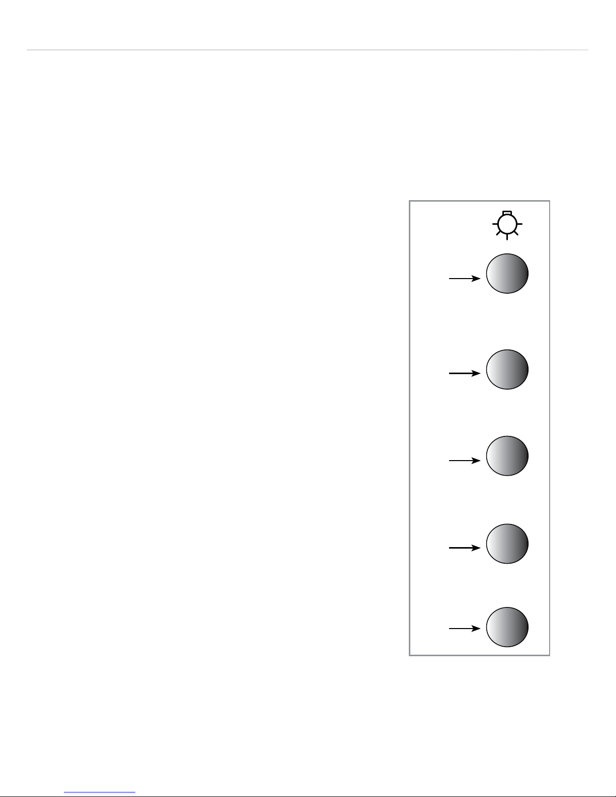
Control Panel (Fig. 1)
A - Light button
B - Intensive speed button
C - Speed 3 button
D - Speed 2 button
E - On (speed 1) and o button
To switch the extractor lights on or o
• Press the light button (A).
To switch on the extractor and change the
speed
• Press button ‘E’ to switch the unit on. Adjust
the speed using buttons ‘B’, ‘C’ & ‘D’.
• You may notice that the intensive speed
(speed 4) indicator flashes when it is
selected. This is not a fault (see page 18 for
more information).
4
0/1
3
2
A
Fig. 1
B
C
D
E
Page 7

7
To activate the timer function
• Press and hold the desired speed button for approximately
5 seconds to activate a 15 minute timer for that speed. The
selected speed’s indicator should flash. Hold the same button for
approximately 5 seconds to cancel the timer. Please note that the
intensive speed automatically switches o after approximately 6
minutes (see page 18 for more information).
To activate the clean air function
• This extractor is equipped with a clean air function that runs the
motor for 10 minutes every hour to help keep the air in the kitchen
refreshed.
• To activate the clean air function, touch and hold buttons ‘D’ and ‘E’
whilst the appliance is o (on standby). Buttons ‘D’ and ‘E’ will flash
whilst the motor is not running to indicate that the function is active.
• To switch o the clean air function, simply press button ‘E’.
To switch the extractor o
• If the extractor is on speeds 2, 3 or 4 press button ‘E’ to revert to
speed 1. Then, press button ‘E’ again to switch the unit o. If the
extractor is already on speed 1, press button ‘E’.
Page 8

8
Care and maintenance
IMPORTANT: DO NOT PERFORM MAINTENANCE OR CLEANING
OF THE EXTRACTOR WITHOUT FIRST SWITCHING OFF THE
ELECTRICITY SUPPLY.
Cleaning
You should use a non-abrasive cleaner. Any abrasive cleaner
(including Cif) will scratch the surface and could erase the control
panel markings.
You can clean your extractor eectively by simply using a dilute
solution of water and mild detergent and drying to a shine with a
clean cloth.
IMPORTANT:
Always protect surfaces immediately beneath the extractor (such
as a hob) with clean, dry towels or similar cushioning items before
carrying out any cleaning or maintenance in case of falling parts/
items.
Removing and cleaning the grease filter
The grease filter should be kept clean to minimise the risk of fire.
At least once a month you should remove and clean the grease
filter with hot soapy water. You can also wash the grease filter in a
dishwasher, ensuring that you place it in an upright position to prevent
damage from other items in the dishwasher. After rinsing and drying,
replace the filter. Cleaning the grease filter in the dishwasher may
lead to discolouration. This is normal and does not constitute a
fault with the appliance.
Page 9
9
Please note: After 30 hours of use the light button will flash to signal
that the filter needs to be cleaned. With the extractor o, press and
hold the lamp button until it stops flashing to reset after cleaning.
To remove the grease filter, lift the catch on the handle on the grease
filter. It will release at the handle side. Lower it towards you slightly
and then remove it completely. To replace the grease filter, repeat the
steps in reverse.
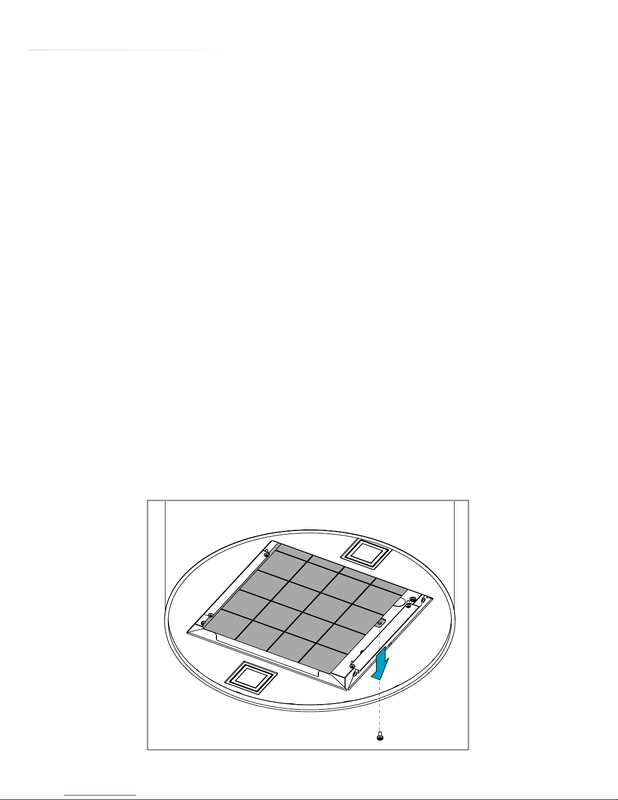
Changing the charcoal filter (re-circulating only) - Fig. 2
To ensure best performance of your extractor, you should replace
the charcoal filter every four to six months, depending on use. To
attach a new charcoal filter, first remove the grease filter as described
above. Remove any old charcoal filter that is in place by removing
the securing screw. Take a new charcoal filter and fit it into position
behind where the grease filter sits. Use the screw in the filter aperture
to hold the charcoal filter in place. Then, re-fit the grease filter.
Fig. 2
Page 10

10
Changing the light bulbs
IMPORTANT: DO NOT PERFORM MAINTENANCE OR CLEANING
OF THE EXTRACTOR WITHOUT FIRST SWITCHING OFF THE
ELECTRICITY SUPPLY. WE RECOMMEND THAT YOU ALWAYS
WEAR PPE (PERSONAL PROTECTIVE EQUIPMENT) WHEN
CARRYING OUT MAINTENANCE.
DO NOT TOUCH SURROUNDING AREAS NOR CHANGE A BULB
DURING OR IMMEDIATELY AFTER USE AS THE BULBS (AND
SURROUNDS) WILL BE EXTREMELY HOT. ALLOW TO COOL
BEFORE CARRYING OUT ANY WORK.
To change a bulb, press on the side of the bulb surround marked
‘PUSH’. The cover should click and then swing open. Using a gloved,
or similarly protected, hand remove the old bulb and insert a new one.
Close the cover until it clicks.
Please note: Avoid touching a new bulb with bare fingers as grease
and other deposits left on the glass of the bulb can lead to premature
failure.
Page 11

11
Installation
When installing this product we strongly recommend you seek the
help of another individual. This product may have some sharp edges.
Please take care and wear adequate PPE when handling.
Installation preparation - height
When the extractor is to be installed above an electric hob, the
minimum distance between the hob and the bottom edge of the
extractor must exceed 650mm.
When the extractor is to be installed above a gas hob, the minimum
distance between the bottom edge of the extractor and hob must
exceed 750mm.
If the instructions provided with your gas hob state that the
required distance between the hob and extractor must be greater
than our measurement, then that is the distance that should be
observed; this is a legal requirement and may lead to your hob
being disconnected from the gas supply and the installation being
reported under RIDDOR (the height should be measured from the
top of the burners).
IN THE ABSENCE OF ANY INSTRUCTIONS SUPPLIED WITH THE
GAS HOB, THE MINIMUM DISTANCE BETWEEN THE HOB AND
EXTRACTOR MUST BE AT LEAST 760mm. The width of any hob
must not be greater than the width of the extractor installed above
it.
Page 12
12
Fig. 3
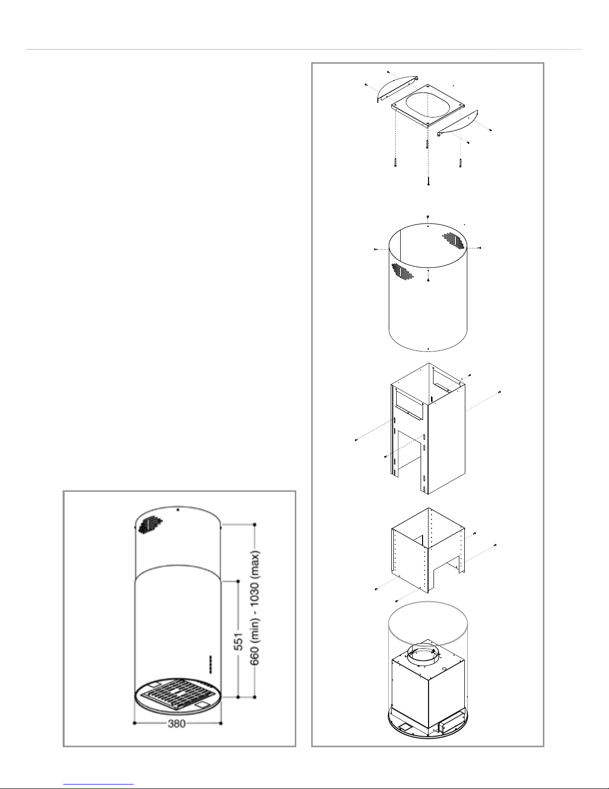
There are images below showing
the extractor dimensions (Fig. 3) and
an exploded view of the installation
components. (Fig. 4). These are
intended to help with installing the
extractor.
Taking into account the extractor
dimensions, and the advice
regarding installation height as
per page 11, roughly mark the
screw hole positions for the ceiling
bracket (shown in Fig. 5).
Ensure that you are happy with
where the extractor will be and the
height it will sit at above the hob or
surface below.
Fig. 4
A
B
C
D
E
Page 13
13
Ducting and ventilation
For best performance and lowest noise output, we recommend the
use of 150mm ducting. You can also use smaller diameter ducting but
this will reduce performance and potentially increase the noise level
of the extractor whilst in use. In general, the less ducting you use (i.e.
distance and bends) the more ecient your extractor will be.
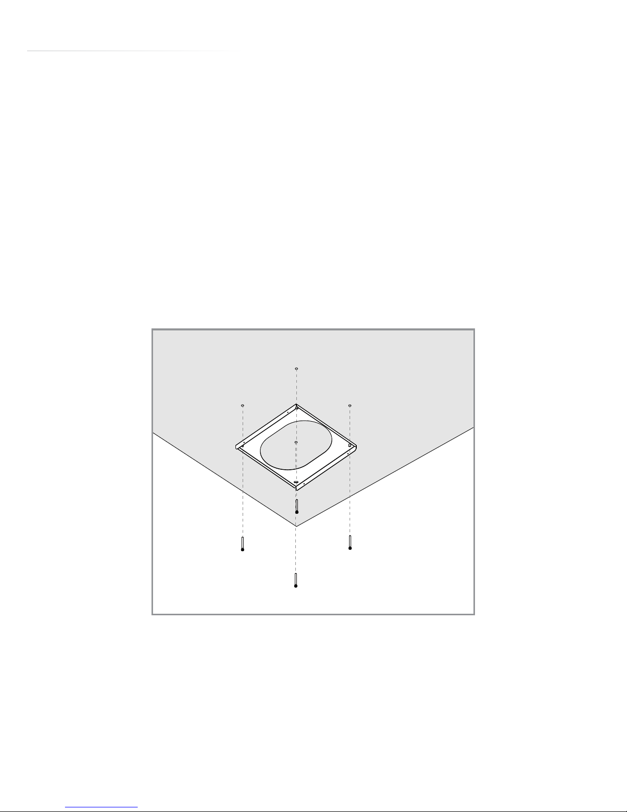
You may wish, at this stage, to fit the ceiling bracket (Fig. 5). Use
fixings (e.g. wall plugs) suitable for the surface to which the extractor is
to be mounted.
Before cutting/drilling through any surfaces, ensure that adequate
measures have been taken to ensure no electrical cables or similar
lie above/behind.
Fig. 5
Page 14
14
Mounting the
extractor
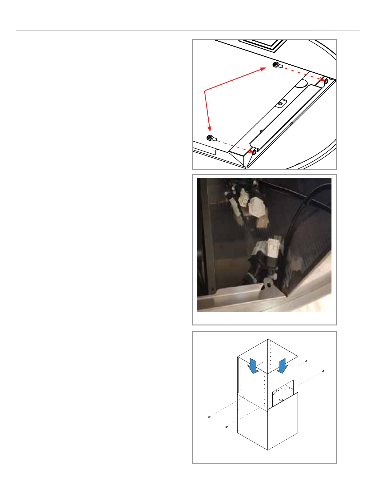
Remove the motor group and
housing by first removing the four
screws holding the group within
the body. Two of these screws are
pictured in Fig. 6. There are two
more on the opposite side.
Raise the motor group and
housing slightly and undo the
cable connections that connect
the wiring to the motor group,
as per Fig. 7. Remove the motor
group from the extractor body.
Attach the motor group and
housing to the lower frame piece
(D in Fig. 4 on page 12) as per Fig.
8.
Attach the upper frame piece (C
in Fig. 4 on page 12) to the ceiling
bracket and fit the chimney piece
support brackets as per Fig. 9.
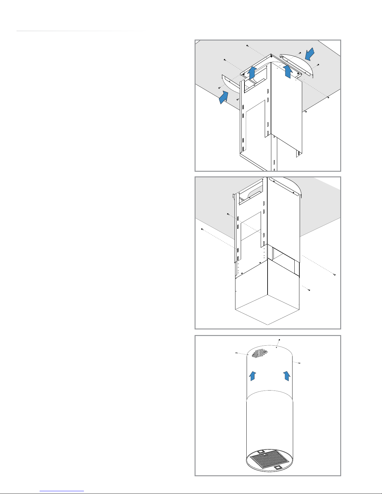
Attach the lower frame piece and
motor group to the upper frame
piece at the required height as per
Fig. 6
Fig. 7
Fig. 8
Page 15
15
Fig. 10. There are lots of screw
holes on the lower frame piece
to help you achieve the correct
installation height.
If you have not already done
so, remove the chimney piece
and peel o the protective film.
Carefully place the chimney piece
back inside the extractor body.
With the help of at least one other
individual, lift the extractor body
up to meet the frame. Whilst one
supports the body, reconnect
the cable connectors that you
disconnected as per Fig. 7.
Re-attach the motor group and
housing to the extractor body
using the screws you removed as
per Fig. 6.
Raise the chimney piece and
secure it to the chimney bracket
support pieces, as per Fig. 11.
Ensure that everything is secure.
Fig. 9
Fig. 10
Fig. 11
Page 16
16
Mains electricity connection
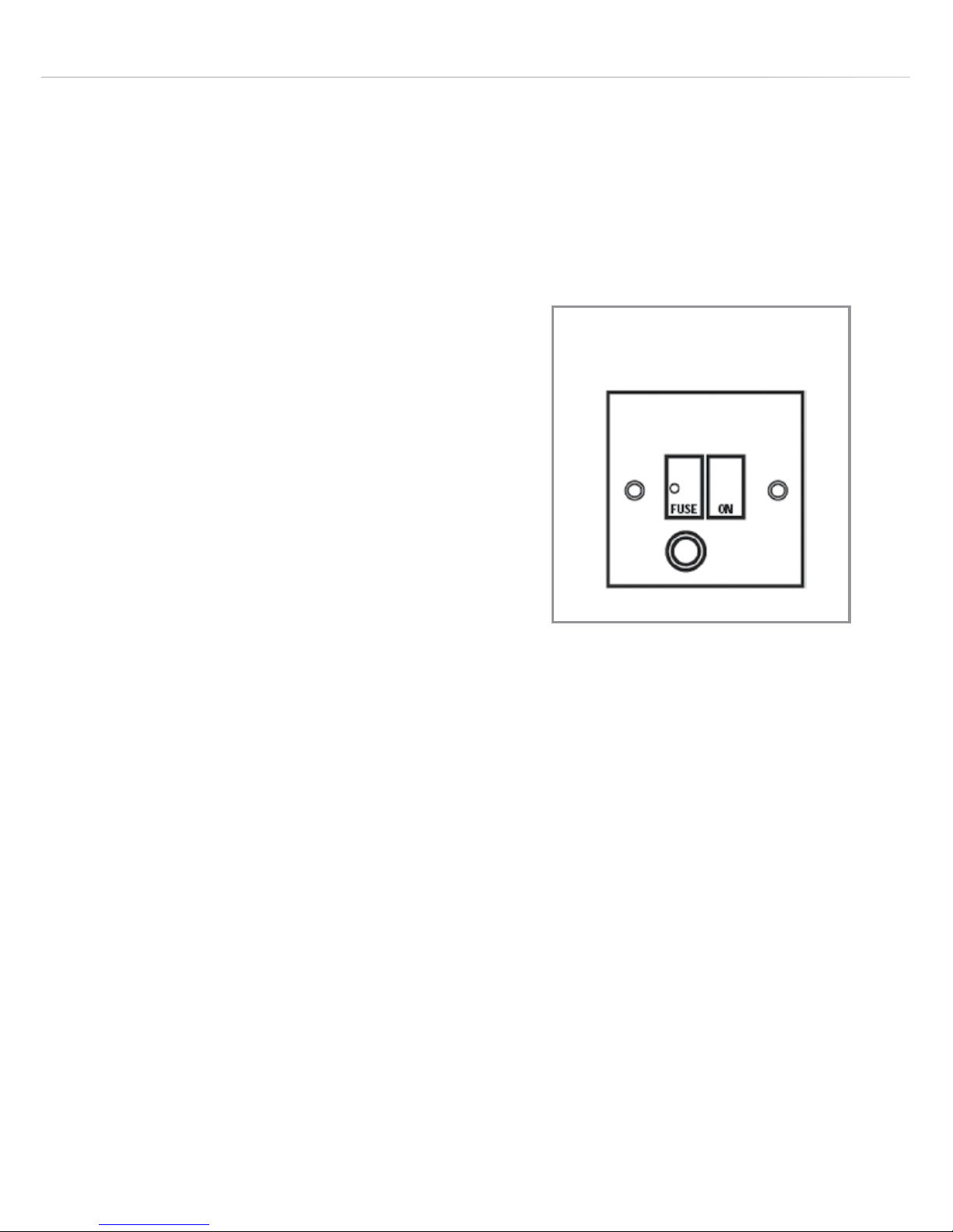
THIS APPLIANCE MUST BE CONNECTED TO THE MAINS SUPPLY
BY A COMPETENT PERSON, USING FIXED WIRING VIA A DOUBLE
POLE SWITCHED FUSED SPUR OUTLET AND PROTECTED BY A
3A FUSE.
We recommend that the appliance is
connected by a qualified electrician,
who is a member of the N.I.C.E.I.C. and
who will comply with the I.E.E. and local
regulations.
The wires in the mains lead of this
appliance are coloured in accordance
with the following code:
BLUE = NEUTRAL, BROWN = LIVE, GREEN+YELLOW = EARTH
As the colours of the wires in the mains lead for the appliance may
not correspond with the coloured markings identifying the terminals
connecting to the fused spur, proceed as follows:
• The wire which is coloured blue must be connected to the terminal
marked N (Neutral), or coloured black.
• The wire which is coloured brown must be connected to the
terminal marked L (Live), or coloured red.
• The wire which is coloured green and yellow must be connected
to the terminal marked E (Earth) or coloured green or green and
yellow.
DOUBLE POLE
SWITCHED
FUSED SPUR OUTLET
USE A 3 AMP FUSE
Fig. 12
Page 17

17
Assembly and electrical connection should be carried out by
competent personnel.
Do not mount the isolation switch behind the chimney section. It is
a requirement that you must be able to isolate the extractor from
the mains electrical supply after installation.
Electrical information
Mains electrical voltage: 220 – 240Vac.
Total rated power consumption: 320W
Troubleshooting
If your extractor is not working:
1. Check that the mains supply has not been switched o.
2. Check that the fuse in the spur has not blown.
If your lights are not working:
1. Check that the mains supply has not been switched o.
2. Check whether the extractor still extracts on any speed. If not,
check the fuse, as above. If the lights still do not work, contact
CDA Customer Care using the details on page 18.
(continued on page 18)
Page 18

18
If you notice speed 4 reverting to speed 3 after approximately 6
minutes:
This is not a fault. Regulations issued by the European Commission in
January 2015 dictate that internal motor extractors with a maximum air
capacity higher than 650m/h must be equipped with a timer device
that automatically switches the speed from ‘4th’, or intensive, to 3rd
after 6 minutes of operation.
If the light button is flashing:
This is not a fault. After 30 hours of usage the light button will flash to
signal that the grease filter needs to be cleaned. Press and hold the
light button to reset after cleaning.
If any of the potential resolutions in this guide do not resolve your
issue, please contact CDA Customer Care using the contact details
below.
Contact CDA Customer Care
A: Customer Care Department, The CDA Group Ltd, Harby Road,
Langar, Nottinghamshire, NG13 9HY
T: 01949 862 012 F: 01949 862 003
E: [email protected] W: www.cda.eu
Page 19
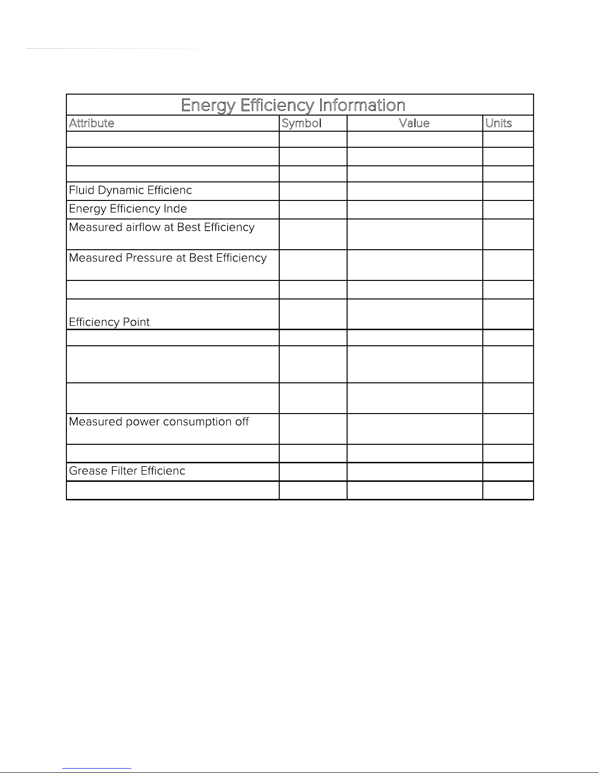
19
Attribute Symbol Units
EVCK41noitacifitnedI ledoM
Annual Energy Consumption AEC
Hood
83 kWh
Time increase factor f 0.98
y FDE
Hood
28.4 (A)
x EEI
Hood
69 (C)
Point
Q
BEP
344.5
m
3
/h
Point
P
BEP
444 Pa
Maximum airflow Q
MAX
739
m
3
/h
Measured electric power at Best
W
BEP
150
39
199
W
Nominal lighting power WL W
Average illumination of the lighting
system on the cooking surface
E
Middle
Lux
Measured power consumption in
standby
P
S
0.45 W
mode
P
O
0 W
Sound power level L
WA
60 dBA
y GFE
Hood
90 (B) %
ELycneiciffe pmaL
Hood
5.1 (F)
Energy Efficiency Information
Value
%
E & O E. All instructions, dimensions and illustrations are provided for guidance only. CDA reserve the
right to change specifications without prior notice.
Page 20

www.cda.eu
Customer Care Department. The CDA Group Ltd, Harby Road, Langar, Nottinghamshire, NG13 9HY
T: 01949 862 012 F: 01949 862 003 E: [email protected]
For service or queries relating to your product please contact:
The Customer Care Department on 01949 862 012 or email [email protected]
For more information please contact:
The Sales Department on 01949 862 010 or email [email protected]
 Loading...