

Page 1
Flush-fitting hob -
front controls
CD 60 - CD 61 - CD 62
Before operating this hob,
please read these instructions carefully
Users Operating Instructions
GB
Page 2

2
Rating Plate
Dear Customer,
Thank you for choosing one of our products.
The warnings and tips given below are intended to protect your safety and that of others. They will also help you
make the most of your appliance.
Keep this booklet in a safe place. It will be useful if you, or
anyone else, have any questions about use of the appliance.
This appliance must only be used for the purpose
for which it was designed, i.e. for cooking foods.
Any other use should be considered incorrect and
therefore dangerous.
The manufacturer is not responsible for damage
caused by improper, incorrect or irresponsible use of
the appliance.
TIPS FOR THE USER
✓
During and immediately after use some parts of the hob can reach very high
temperatures. Do not touch them.
✓
Keep children away when the hob is in use.
✓
After using the hob make sure that all of the knobs are turned off. Turn off the
main tap of the gas supply pipe or the cylinder tap if appropriate.
✓
When you are not using the hob it is a good idea to turn off the gas supply
tap.
✓
Regular lubrication of the gas taps must only be performed by qualified
engineers. If the gas taps are not working properly call the After-Sales Service.
Page 3

WARNINGS FOR THE USE OF ELECTRICAL APPLIANCES
When using any electrical appliance some important rules must always be followed.
In particular:
✓
do not touch the appliance with wet or damp hands or feet
✓
do not use the appliance with bare feet
✓
this appliance should only be used by responsible adults.
3
IMPORTANT WARNINGS AND TIPS
✓
When unpacking the appliance make sure that it is not damaged. If you have any
doubts, do not use the appliance but consult your supplier or an engineer.
✓
The packing materials (plastic bags, expanded polystyrene, nails, bands etc.) must
not be left within easy reach of children, as these may result in serious injury.
✓
The packaging material is recyclable and is marked with the recycling symbol .
✓
Do not try to alter the technical properties of the appliance, because this could be
dangerous.
✓
The manufacturer cannot be considered responsible for damage caused by
improper, incorrect or irresponsible use of the appliance.
✓
Before disposing of any unwanted appliances it is recommended that all potentially
hazardous parts be made harmless.
✓
The appliance should be installed and all the electrical connections made by a qualified engineer in compliance with local regulations in force and following the manufacturer's instructions.
CE Declaration of conformity
✓
This hob is intended to come into contact with food products and conforms with
European Directive 89/109/EEC.
✓
This hob (Class 3) has been designed for use only as a cooking appliance. Any other
use (e.g. heating rooms) should be considered incorrect and therefore dangerous.
✓
This hob has been designed, constructed and put on to the market in conformity
with
✓
Safety requirements of the "Gas" Directive 90/396/EEC;
- Safety requirements of the "Low Voltage" Directive 73/23/EEC;
- Protection requirements of the "EMC" Directive 89/336/EEC;
- Requirements of Directive 93/68/EEC.
These instructions are only valid for those countries whose identification
symbol appears on the cover of the instruction booklet and on the appliance.
Page 4
4
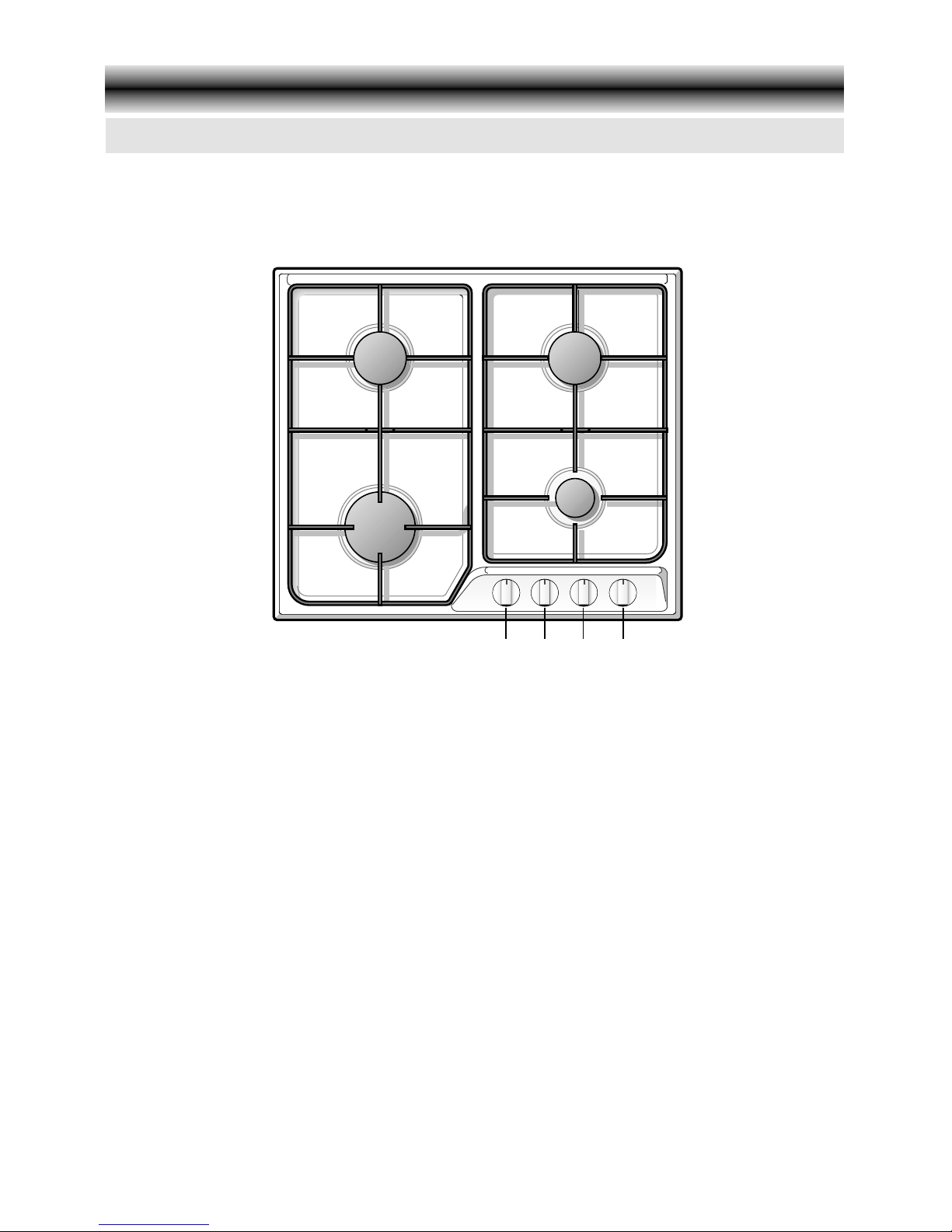
COOKING POINTS
1. Rapid burner (R) - 3,00 kW
2. Left medium-speed burner (SR) - 1,75 kW
3. Right medium-speed burner (SR) - 1,75 kW
4. Auxiliary burner (A) - 1,00 kW
CONTROL PANEL
5. Rapid burner control knob (1)
6. Left medium-speed burner control knob (2)
7. Right medium-speed burner control knob (3)
8. Auxiliary burner control knob (4)
This appliance is class 3
NOTE:
✓ The electric ignition is incorporated in the knobs
Gas hob
Model: CD 60
Figure 1
2
8
765
3
4
1
Page 5
5
This appliance is class 3
NOTE:
✓ The electric ignition is incorporated in the knobs
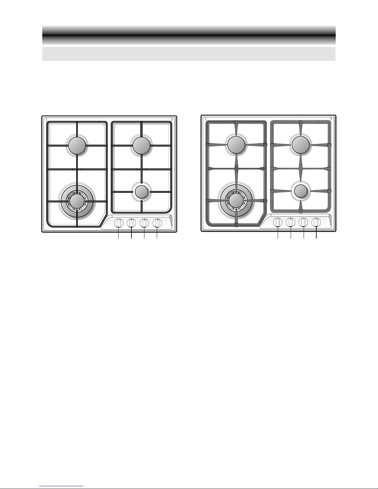
COOKING POINTS
1. Triple-ring burner (TR) - 3,30 kW
2. Left medium-speed burner (SR) - 1,75 kW
3. Right medium-speed burner (SR) - 1,75 kW
4. Auxiliary burner (A) - 1,00 kW
CONTROL PANEL
5. Triple-ring burner control knob (1)
6. Left medium-speed burner control knob (2)
7. Right medium-speed burner control knob (3)
8. Auxiliary burner control knob (4)
Gas hob with triple-ring burner
Models: CD 61 - CD 62
Figure 2
Model: CD 61
Model: CD 62
2
8
765
3
4
1
2
8
765
3
4
1
Page 6
6
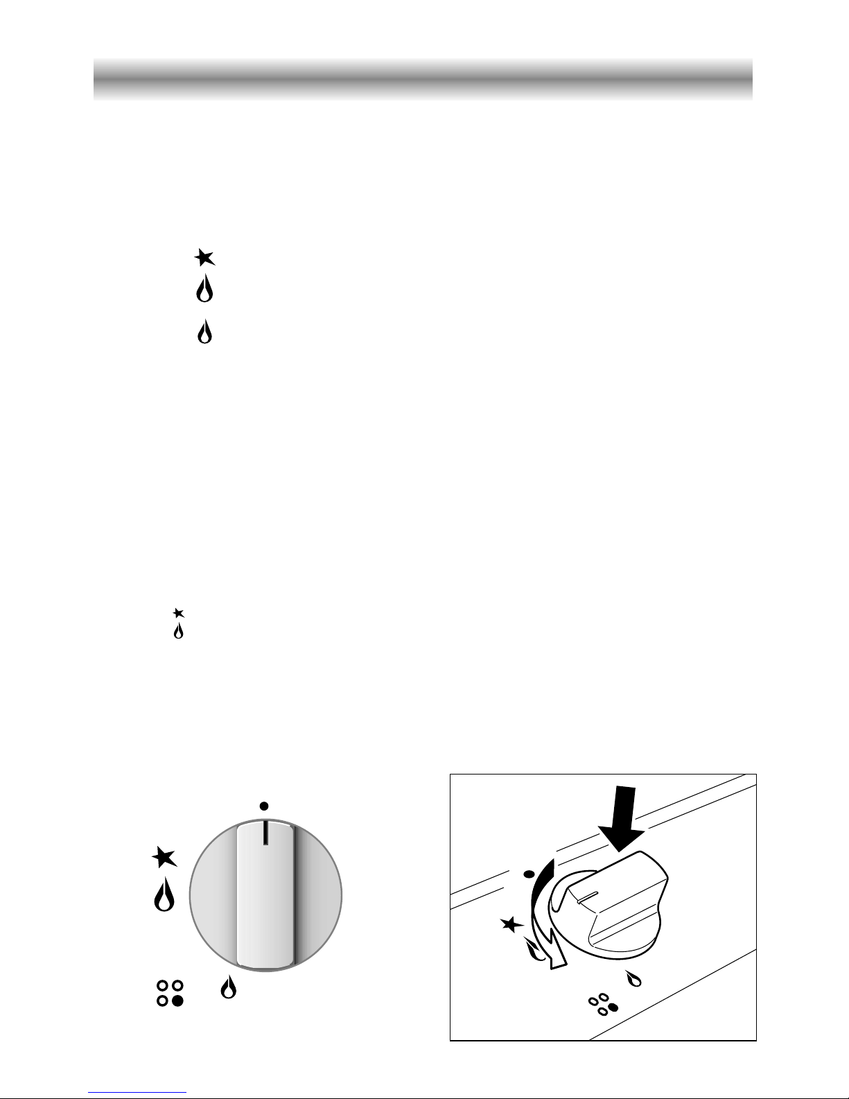
GAS BURNERS
Gas flow to the burners is adjusted by turning the knob illustrated in fig. 3 which controls the safety valves.
Turning the knob so that the indicator line points to the symbols printed on the panel
achieves the following functions:
✓
full circle ● = closed valve
✓
symbol = maximum aperture or flow
✓
symbol = minimum aperture or flow
The maximum aperture position permits rapid boiling of liquids, whereas the minimum
aperture position allows slower warming of food or maintaining boiling conditions of
liquids.
To reduce the gas flow to minimum, rotate the knob further anti-clockwise to point
the indicator towards the small flame symbol.
Other intermediate operating adjustments can be achieved by positioning the indicator
between the maximum and minimum aperture positions, not between the maximum
aperture and closed positions.
LIGHTING OF BURNERS
To ignite the burners follow these instructions:
–
Lightly press the knob (fig. 4) in an anti-clockwise direction up to the maximum aperture
(symbol ); press the knob right down to prime the electric ignition until the burner lights.
In case of power cut manually light the burner.
– Adjust the burner according to the power required.
If the burner fails to ignite repeat the ignition with the knob on “minimum” position.
Figure 3 Figure 4
Use Of the Hob
Page 7

7
PAN DIAMETER
BURNER MINIMUM MAX.
Auxiliary 12 cm 14 cm
Medium-speed 16 cm 20 cm
Rapid 20 cm 24 cm
Triple-ring 24 cm 28 cm
CHOICE OF BURNER
The symbols printed on the panel by the side of the knob indicate which burner you
are controlling.
Choose a suitable burner depending on the cookware diameter and capacity.
The pan diameter should be suitable for the burner power to make the most of the
burner's high efficiency and not waste fuel.
A small pan does not boil more quickly on a large burner (fig. 5).
Attention: During use the hob becomes very hot under the cooking zones.
Keep children away.
Figure 5
WRONG
CORRECT
Flat-bottomed pans should be placed directly onto the pan-support.
When using a WOK always place the supplied stand in position over the burner to maintain the correct operation of the triple-ring burner (Fig. 5a - 5b).
Figure 5b
Figure 5a
CORRECT USE OF WOK PAN ADAPTER - Model CD 61 only
IMPORTANT:
The special grille for wok pans (fig. 5b) MUST BE PLACED ONLY over the panrest for the triple-ring burner.
(*) Model CD 61 only: wok pans have to be used only with the special grille fitted
Wok (*) max 36 cm
do not use pans with concave or convex bases
(see Ïcorrect use of wok pan adapter).
Page 8

8
GENERAL TIPS
✓ Before cleaning the hob switch it off and wait for it to cool down.
✓ Clean with a cloth, hot water and soap or liquid detergent.
✓ Do not use products which are abrasive, corrosive or chlorine based.
✓ Do not use steel pads.
✓ Do not leave acid or alkaline substances (vinegar, salt, lemon juice, etc.) on the
hob.
ENAMELLED PARTS
✓ All the enamelled parts must be washed only with a sponge with soapy water or
other non-abrasive products.
✓ Dry carefully.
STAINLESS STEEL HOB
✓ Clean with special products which are available on the market.
✓ Dry preferably with chamois leather.
✓ Note: regular use will cause discolouring around the burners, because of the high
flame temperature.
BURNERS AND GRIDS
✓ These pieces can be removed and washed with suitable products.
✓ After cleaning burners and spreaders dry them well and replace them correctly.
✓ In appliances with electric ignition keep the electrode clean so that the sparks
always strike.
✓ Note: To avoid damage to the electric ignition do not use it when the burners
are not in place.
GAS TAPS
✓ Regular lubrication of the gas taps must only be performed by specialised engineers.
✓ If the gas taps are not working properly call the After-Sales Service.
Cleaning and Maintenance
Page 9

9
CORRECT POSITIONING OF THE BURNERS
It is very important to check that spreader F and cap C of the burner (see Figure 6) are
perfectly in place because if they move out of place serious problems could arise.
Make sure that electrode "S" (Fig. 6) is kept clean so that the sparks always strike.
TRIPLE-RING BURNER
The triple ring burner must be correctly positioned (see fig. 7); the burner rib must be
located in position as shown by the arrow.
The burner correctly positioned must not rotate (fig. 8).
Then position the cap A and the ring B (fig. 8).
A
B
Figure 6
Figure 7
Figure 8
S
F
C
Page 10

10
580
550
100
min
500
470
35 min.
IMPORTANT
✓The hob should only be installed by a qualified installer.
Failure to observe this rule leads to cancellation of the guarantee.
✓The appliance must be installed correctly, in compliance with the regulations in
force and following the manufacturer's instructions.
✓Any repair or maintenance must be performed with the appliance switched off.
✓These appliances have been designed and manufactured to be fitted into heat-
resistant units.
✓These hobs are designed to be fitted into 600 mm deep kitchen units.
✓The unit walls must not be higher than the working surface and must withstand
a temperature of 75°C more than room temperature.
✓Avoid installation near inflammable materials (e.g. curtains).
Tips for installation
Figure 9
Installation
Page 11

11
To fit the hob into the unit make an opening of the dimensions given in Figure 9,
remembering that:
✓Inside the unit there must be a space of at least 30 mm between the bottom of the
hob and the top of a shelf.
✓Any wall to the side and above the hob must be at least 100 mm away (Fig. 9).
✓The wall behind the hob must be at least 35 mm away (Fig. 9).
✓When there is a wall unit or hood above the hob there must be at least 750 mm
between the hob and the unit or hood (see also Fig. 10).
✓A partition between the base of the hob and the cupboard below should be fitted.
750 mm
Figure 10
Page 12

12
30 mm
Space for
connections
Depression
space
Door
INSTALLATION ABOVE UNITS WITH DOORS (fig. 11)
The unit must be so constructed that the movement of air caused by closing and opening, even violent, of the doors does not cause the burners to go out.
Leave a depression space of 30 mm between the bottom of the hob and the top of the
unit (Fig. 11).
MOUNTING THE FASTENING TABS (fig. 12)
✓Each hob is supplied with a set of tabs and screws to fasten it to units from 2 to 4 cm
thick.
✓Turn the hob over and put tabs "A" into the mountings; only tighten screws "B" a few
turns. Do not over tighten.
✓Make sure that the tabs are mounted correctly as shown in Figure 12.
FASTENING THE HOB (fig. 12)
✓Stretch gasket "C" above the unit along the edge of the hole made, being careful to
overlay the joining edges.
✓Put the hob into the hole cut into the worktop and position it correctly.
✓Put tabs "A" into place and tighten screws "B" until the hob is completely secured.
✓Carefully trim away the excess gasket material from around the hob.
20 mm min.
40 mm max.
B
C
A
Figure 12Figure 11
Page 13

13
INSTALLATION ROOM
The room where the gas appliance is to be installed must have a natural flow of air
so that the gas can burn.
The flow of air must come directly from one or more openings made in the outside
walls with a free area of at least 100 cm
2
.
If the appliance does not have a flame-failure safety device this opening must have
an area of at least 200 cm
2
.
The openings should be near the floor and preferably on the side opposite the exhaust
for combustion products and must be so made that they cannot be blocked from
either the inside or the outside.
If it is not possible to vent in this way it is possible for air to come from an adjacent
room which is ventilated as required, as long as it is not a bedroom or a dangerous
area.
In this case the kitchen door must be left open to allow air movement.
DISCHARGE OF THE COMBUSTION PRODUCTS
The gas appliance combustion products must be discharged through a hood
connected directly to the outside (Fig. 13).
When this is not possible an electric fan can be used, fitted on the outside wall or
the window, with output which guarantees a daily exchange of air of 3-5 times the
volume of the kitchen (Fig. 14).
The fan can only be installed if there are air inlet openings as described in the
"Installation room" section.
H min 750 mm
Air inlet
opening
Air inlet
opening
Electric fan to
extract combustion
products
Combustion
product extractor
hood
Figure 13
Figure 14
Page 14

14
TYPES OF GASES
There are two types of gas suitable to use with this appliance.
✓G30 / G31
✓G20
INSTALLATION
The appliance is set at the factory to operate with the gas indicated on the rating plate
on the appliance.
If the appliance must be operated with a gas different than that indicated on the plate,
it is necessary to make the following changes:
✓gas connection
✓replacement of the injectors
✓regulating of the minimum flame.
GAS CONNECTION
Cat: II 2H3+
The connection must be executed by a suitably qualified person according to the relevant standards.
The fitting (fig. 15a and 15b) is made up of:
✓1 nipple “A”
✓1 biconical gasket ring “B”
✓1 elbow fitting “C”
✓gasket “F”
GB
F
A
C
B
Figure 15a
Gas Section
F
A
C
F
Figure 15b
Page 15

15
CONNECTION TO THE GAS SUPPLY
The gas connection must be made in compliance with the local regulations in force.
Be careful when flexible pipes are used that they do not come into contact with
moving parts.
To maintain the thickness of 3 cm, the hob is fitted with a channel to contain the
connection pipe.
The gas inlet union can be turned in the direction required after the union C (figures
15a and 15b) and nipple A connection has been slackened with two spanners (Fig.
16).
Never put it in the horizontal or vertical position.
IMPORTANT:
✓Never attempt to turn the elbow “C” without having first slackened off
the relative lock nipple “A”.
✓The seal “F” and the biconical gasket “B” (fig. 15a - 15b) guarantees the
seal of the gas connection.
It is recommended that they be replaced whenever they show even the
slightest deformation or imperfection.
✓After connecting to the mains, check that the couplings are correctly
sealed, using soapy solution, but never a naked flame.
✓The connection with rigid metal pipes should not cause stresses to the
hob base.
Figure 16
Page 16

16
REPLACING THE BURNER INJECTORS
Injectors can be obtained from our After-Sales Department.
Choose the injectors to be replaced according to the table below.
The injector diameter, expressed in hundredths of a millimetre, is marked on the
injector body.
To replace the injectors proceed as follows:
✓ Remove the gratings, the burner covers and the knobs;
✓ Using a wrench, substitute the nozzle injectors “J” (Fig. 17) with those most suitable
for the kind of gas for which it is to be used.
The burners are made in such a way so as not to require regulation of the
primary air.
J
TABLE FOR THE CHOICE OF THE INJECTORS
GB
Cat: II 2H3+
[Hs - kW] [Hs - kW]
Ø injecteur Ø injecteur
[1/100 mm] [1/100 mm]
Auxiliary (A) 1,00 0,30 0,50 0,72
Semi-rapid (SR) 1,75 0,45 0,65 0,97
Rapid (R) 3,00 0,75 0,85 1,15
Triple ring (TRC) 3,30 1,50 0,91 1,24
G30/G31
28-30/37 mbar
REDUCED
POWER
(HS - kW)
NOMINAL
POWER
(HS - kW)
BURNER
G 20
20 mbar
Figure 17
Page 17

17
ADJUSTING THE GAS BURNER MINIMUM
For taps with adjusting screw inside the shaft (fig. 18):
✓ using a screwdriver max. diameter 3 mm turn the screw inside the tap shaft until
the flame setting is correct.
For taps with adjusting screw on the body (fig. 19):
✓ using a screwdriver turn screw "A" until the flame setting is correct.
Normally for G30 gas, fully tighten the adjustment screw.
LUBRICATING THE GAS TAP
If a gas tap is difficult to turn, disassemble it, clean it carefully with petrol and spread
a little high-temperature-resistant grease on it.
These operations must be performed by a specialised engineer.
A
Figure 18 Figure 19
Page 18

18
IMPORTANT: The installation must be made following the manufacturer's
instructions and in accordance with existing laws.
Incorrect installation may be dangerous and the manufacturer can not be
held responsible.
Warning! This appliance must be earthed
A properly earthed three pin plug (fused at 3 amps, to BS 1362 ASTA approved) must
be used. As the colours of the wires in the mains lead of this appliance may not
correspond with the coloured markings identifying the terminals in your plug, proceed
as follows.
The wire which is coloured GREEN & YELLOW must be connected to the terminal in
the plug which is marked with letter "E" or by the Earth symbol or coloured GREEN
& YELLOW.
The wire which is coloured BLUE must be connected to the terminal which is marked
with the letter "N" or coloured BLACK.
The wire which is coloured BROWN must be connected to the terminal which is
marked with the letter "L" or coloured RED.
Green &
Yellow
Earth
3 amp fuse
Blue Neutral Brown Live
Figure 20
Electrical Connection
Page 19

19
230 V
L1 N(L2)PE
SECTION OF THE SUPPLY CABLES - TYPE “H05V2V2-F”
resistant to temperatures of 90°C
230 VAC 50 Hz3 x 0,75 mm2
✓ The electrical cable must be connected to the terminal board following the
diagrams of Fig. 21.
The appliance must be earthed.
The manufacturer declines all responsibility for any problem caused by
failure to observe this rule.
Figure 21
IMPORTANT INFORMATION FOR CORRECT DISPOSAL OF THE PRODUCT IN
ACCORDANCE WITH EC DIRECTIVE 2002/96/EC.
At the end of its working life, the product must not be disposed of as
urban waste. It must be taken to a special local authority differentiated
waste collection centre or to a dealer providing this service.
Disposing of a household appliance separately avoids possible negative consequences for the environment and health deriving from inappropriate disposal and enables the constituent materials to be recovered to obtain significant savings in energy and resources. As a
reminder of the need to dispose of household appliances separately,
the product is marked with a crossed-out wheeled dustbin.
Page 20

Flush-fitted hob - front controls
Continental Domestic Appliances
Nottingham NG72SD
1101403.1
ß13
 Loading...