

Page 1
Before operating this oven,
please read these instructions carefully
Users Operating Instructions
Gas Ovens
CD 307 ..
GB
Page 2

INSTALLATION
The oven must be installed in accordance with the installation instructions contained in
this booklet. Connection to the electricity supply must be made by a competent
electrician to a suitable 13 amp. switched socket.
Warning this appliance must be earthed.
BEFORE USE
Please ensure that all packing has been removed from the appliance before switching
on.
2
Dear Customer
Thank you for choosing one of our appliances, carefully designed and built by
our specialist staff and thoroughly tested to satisfy your cooking requirements.
We suggest that you read this Instruction Booklet so that you will understand
fully how to operate your appliance.
Please keep the booklet handy. You may wish to refer to it at a later date.
CDA
IMPORTANT INFORMATION FOR CORRECT DISPOSAL OF THE
PRODUCT IN ACCORDANCE WITH EC DIRECTIVE 2002/96/EC.
At the end of its working life, the product must not be disposed of as
urban waste. It must be taken to a special local authority differentiated waste collection centre or to a dealer providing this service.
Disposing of a household appliance separately avoids possible negative consequences for the environment and health deriving from
inappropriate disposal and enables the constituent materials to be
recovered to obtain significant savings in energy and resources. As a
reminder of the need to dispose of household appliances separately,
the product is marked with a crossed-out wheeled dustbin.
Page 3
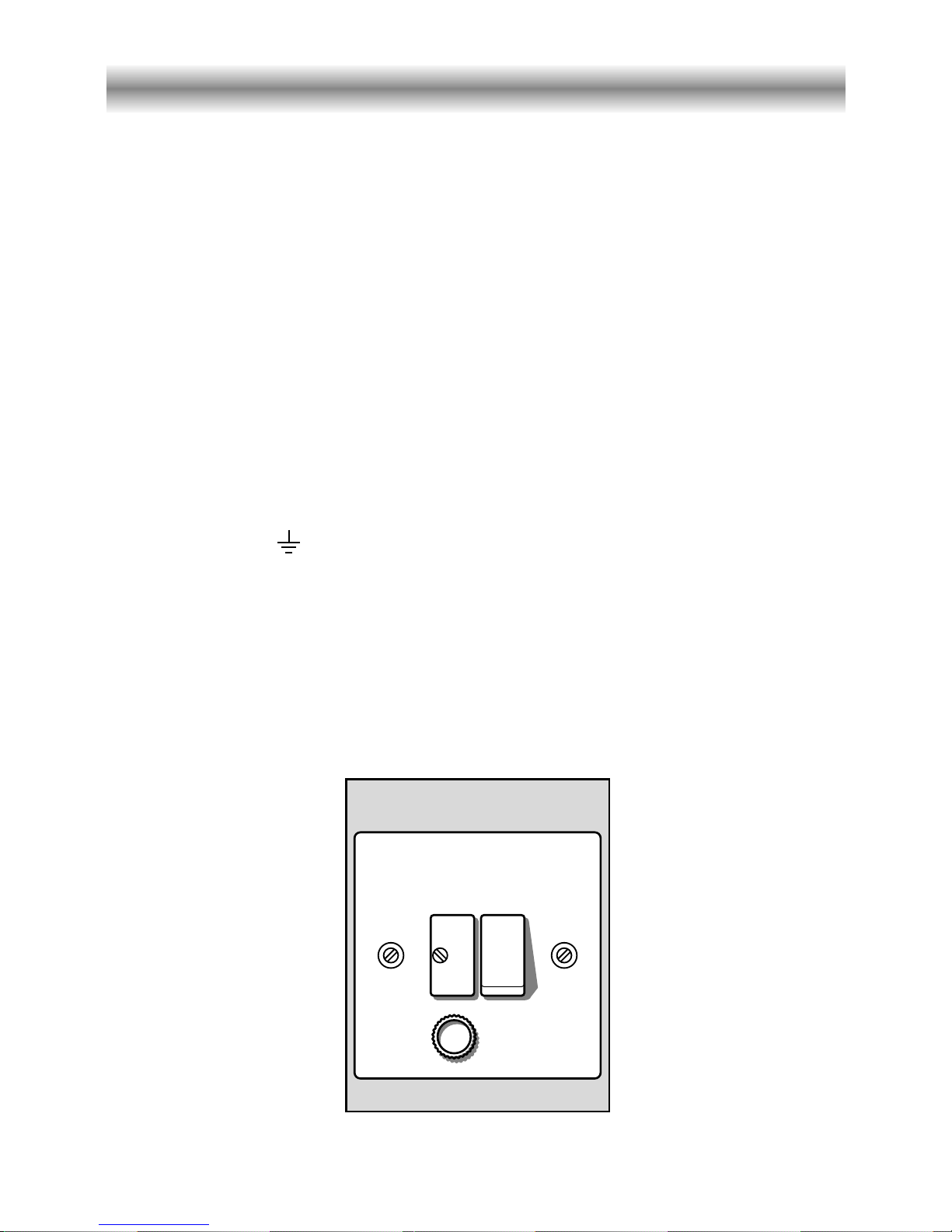
WARNING! THIS APPLIANCE MUST BE EARTHED.
✓
This appliance must be connected by a competent person, using fixed wiring via a
DOUBLE POLE SWITCHED FUSED SPUR OUTLET.
We recommend that the appliance is connected by a qualified electrician, who is a
member of the N.l.C.E.l.C. and who will comply with the l.E.E. and local regulations.
The wires in the mains lead are coloured in accordance with the following code:
Green & Yellow = Earth,
Blue = Neutral,
Brown = Live.
As the colours of the wires in the mains lead for the appliance, may not correspond
with the coloured markings identifying the terminals in your spur box, proceed as
follows:
1) The wire which is coloured green and yellow must be connected to the terminal
marked E (Earth) or coloured Green.
2) The wire which is coloured blue must be connected to the terminal marked N
(Neutral), or coloured Black.
3) The wire which is coloured brown must be connected to the terminal marked L
(Live), or coloured Red.
Figure 1
Electrical supply to your oven
3
FUSE
DOUBLE POLE SWITCHED
FUSED SPUR OUTLET
USE A 13 AMP FUSE
ON
Page 4

4
Gas supply requirements
This appliance should be fitted by a Corgi registered fitter. The installation must comply
with Gas Supply Regulations 1972 and the relevant codes of practice.
CDA are not legally able to provide any assistance in the installation of gas appliances
except to Corgi registered installers. Any Corgi registered fitter requiring help must provide name, address and registration number.
Information supplied will be validated before help is provided.
This appliance is suitable for conversion to liquid petroleum gas. A kit should be
available from the place of purchase. Do not attempt to fit the kit yourself.
If installation is to be carried out using a flexible connector (to BS669), then the
following points must be adhered to:
Note: The gas installation pipes and the final connection to the appliance connecting
pipe shall be sufficient size to maintain the heat output of the appliance as specified
under installation.
1. The appliance flexible connector should not be subject to undue forces, either in
normal use whilst being connected or disconnected.
2. The appliance flexible connector should not be subject to excessive heat by direct
exposure to flue products or by contact with hot surfaces.
Note: The flexible connector must be able to withstand temperatures up to and
including 95°C.
3. The socket into which the plug of the appliance flexible connector fits should be
permanently attached to a firmly fixed gas installation pipe and positioned such that
the hose hangs freely downwards.
4. The appliance flexible connector should be positioned such that it will not suffer
mechanical damage; eg abrasion from the surrounding kitchen furniture which may
be moved in use, such as a door or drawer, or by being trapped by a stability
device.
5. The plug-in connector should be accessible for disconnection after moving the
appliance.
6. After connecting to the mains, check that the couplings are correctly
sealed, using soapy solution, but never a naked flame.
Page 5

5
Ventilation
All rooms are required to have a window which can be opened or the equivalent.
Some rooms will also be required to install a permanent vent in addition to a window
(see table below).
This unit must not be used in a room with a volume of less than 5m
3
.
Room Volume Air vent necessaly (effective area)
5 m3to 10 m
3
50 cm
2
Greater than 11 m
3
No air vent necessary
A room 5 m
3
to 10 m3with a door No permanent air vent
opening to the outside necessary
The above requirements allow also for use of a gas hob but if there are other fuel
burning appliances in the same room, BS5440: 1976 should be consulted to
determine the necessary air vent requirements.
The oven is designed to fit into a cabinet of 600 mm width.
The oven can be built in or built under the kitchen units, but you must ensure that it is
properly ventilated.
In the diagram the built in oven is ventilated by means of a space at the top of the
kitchen cabinet. There are many other methods of ventilating your oven.
Consult a qualified engineer for advice.
IMPORTANT: If the oven is being installed into a built under oven housing unit ensure
that the front rail at the top of the unit is not installed as it will restrict ventilation.
Page 6
6
How to install your oven
Ensure that air can flow freely around the housing area.
If the oven is being installed into a fully enclosed built under oven housing
unit it may be necessary to cut a small slot in the top of the plinth fitted under
the unit. Cut a section 400 mm wide and a minimum of 1 5 mm high to allow air to
pass under the unit.
Failure to allow adequate ventilation to the appliance may
result in over heating or damage to adjacent units.
560
591
594
594
540
20
555
min.
550
560
50
585
Figure 2
Lift the oven carefully into position on the shelf, taking
care NOT to lift it by the door handle. If you lower the
oven door, you will see 4 screw holes, 2 on each side
of the oven.
The oven should then be secured to the housing by
fitting screws into these holes.
Remember the housing should not be free standing
but secured to the wall and/or
adjacent fittings.
Page 7

7
Installation to L.P.G. (for fitters use only)
This appliance is regulated to work with
natural gas.
If it has to work with another type of
gas (L.P.G.), before the appliance is
connected you must substitute the oven
burner injector as follows:
✓
Open the oven door completely.
✓
Remove the burner cover (Fig. 3).
✓
Remove the burner by unscrewing
the two front screws (Fig. 4).
✓
Unscrew the oven burner injector
(Fig. 5) using a 7mm spanner and
substitute it with one (see table) of
the correct size.
✓
Replace all the components by fol
lowing in reverse the operations
explained above.
Figure 3
Figure 4
Figure 5
Page 8

8
TABLE FOR THE INJECTORS
BURNERS
REGULATION OF THE MINIMUM FLAME
(FOR FITTERS USE ONLY)
NOTE: The flame has been regulated for use with Natural Gas, however, when
converting to L.P.G. the flame may need adjusting.
Turn the thermostat to the maximum setting and pre-heat the oven, without grill pan
and base plate, for approximately ten minutes, turn the control to the 125 position.
Remove the knob and adjust the thermostat by-pass screw (Fig. 6) to obtain a short
sharp stable flame. (The flame is visible through the holes in the oven base).
Check that moving the control knob from the maximum flame position to the 125
setting, or rapidly opening and closing the oven door does not make the flame go
out.
G 30 - 28-30 mbar G 20
G31- 37 mbar 20 mbar
OVEN 3,000 0,650 40 83 15 * 125 4 *
Nominal
Power
[kW]
Reduced
Power
[kW]
Ring opening
[mm]
Ø injector
[1/100 mm]
By-pass
[1/100 mm]
Ring opening
[mm]
Ø injector
[1/100 mm]
By-pass
[1/100 mm]
GB
Cat: II 2H3+
adjustable
*
= Reference value
Page 9

9
G
Because of different gas mixtures in the distribution system, you may have flames with
too much or too little air. In such cases, loosen the screw and move the air ring to
close or open the air flow, until the regular flame is obtained (fig. 7).
Standard position of the air ring.
Natural Gas: Positioning the indicator line of the air ring to the symbol N printed on
the burner.
L.P.G.: Fully open the air ring.
Warning: The regulation of the flames must only be carried out by a Corgi registered
fitter.
Flames regulation of the oven burner
Figure 6
Figure 7
Opening ring.[mm]
Page 10

10
Locate the wire side frames as indicated in Fig. 8.
Slide in, on the guides, the shelf and the tray etc. (Fig. 9).
The rack must be fitted so that the safety catch, which stops it sliding out, faces the inside
of the oven (Fig. 9).
Before using the oven for the first time, we recommend that you clean it with soapy
water, rinse carefully and heat for 30 minutes at maximum temperature.
A slightly unpleasant smell may be produced, caused by grease remaining on the oven
elements from the production process.
How to use your gas oven
Figure 8
Figure 9
Page 11

A B
C
11
How to use your gas oven
A. Temperature Selector/lgnition
Light the oven with the door open, lightly press and turn the thermostat knob (A)
anti-clockwise to the desired setting. Press the knob right in to operate the electronic
ignition. Hold it in for 10 -15 seconds after the flame has lit.
If the oven fails to light using the electronic ignition it can be lit with a match (fig. 11).
If there is a fault refer to APPLIANCE SERVICING.
Figure 10
Figure 11
Lighting of oven burner
The thermostatic tap controlling the gas supply to the burner is equipped with a safety
device which automatically stops the gas flow in case of flame extinction. The temperature is constantly maintained on the set value.
The electric ignition starts up by pressing the thermostat knob.
A safety device prevents the electric ignition from functioning when the oven
door is shut.
Page 12

12
C. Timer
The timer can be set to a maximum of 60 minutes. Turn the dial clockwise to the maximum setting of 60 minutes then turn it anti-clockwise until it reaches the desired time.
When the set time expires the timer bell will sound.
NOTE:
The oven will not switch itself off at the end of the timed period.
Safety devices
For safety reasons, it is not allowed to use the oven burner and the electric grill together, at the same time.
The electric grill only operates when the oven thermostat control knob is on
position
● (out), as:
–
when the oven burner is alight a safety device stops the ignition of the electric grill
.
–
if the electric grill is on, the same safety device cuts off the element if the oven thermostat control knob is turned on.
1 - Max Grill with the door closed. Set the temperature to the desired setting
which can be varied between 1 and max. Before using the grill, pre-heat
for about 5 minutes.
Position the grill pan on the highest shelf position and check continually
as food could easily burn. The indicator light will cycle with the grill element.
Grill with the knob set to Max position for maximum 15 minutes, then
to position 4 for maximum 15 minutes.
Caution: the oven door becomes very hot during operation.
Keep children well out of reach.
B. Grill and Light Selector
The light will switch on automatically while grilling and can be selected
when using the oven.
Page 13

Cooking guide
Your gas oven is a newly designed oven which incorporates an indirect burner located
under the oven base plate.
If you have previously been used to cooking with gas you may need to slightly alter
your cooking methods. The bottom of the oven is hot and is ideal for browning the
underside of shallow pastry dishes and pizzas. Other items should be cooked nearer
the top of the oven.
When baking cakes, scones etc on more than one shelf the best results will be
achieved by swapping the shelf positions over half way through the cooking process.
SAFETY
NEVER allow fat to build on the oven base.
As with all ovens, clean and empty fat regularly from the trays and oven base to avoid
the possibility of fat fires.
The oven contains a cooling fan at the top of the appliance which forces cool air over
the fascia panel when the oven reaches a set temperature to prevent it from becoming
too hot.
The fan will continue to operate after the oven has been switched off, until the
appliance cools down. However, the oven door can become hot - keep children away
from this appliance.
NEVER place anything on the bottom of the oven.
Do not line the oven walls with aluminium foil.
Do not place baking trays or the drip tray on the base of the oven chamber.
USE OF THE GRILL
Preheat the oven for about 5 minutes with the door closed.
Introduce the food to be cooked, positioning the rack as close to the grill as possible.
The dripping pan should be placed under the rack to catch the cooking juices and
fats.
Grill with the knob set to Max position for maximum 15 minutes, then to position 4
for maximum 15 minutes.
Do not grill for longer than 30 minutes at any one time.
Caution: the oven door becomes very hot during operation. Keep children
well out of reach.
Page 14

14
Temperature recipe guide
MARK
APPROX. HEAT OF TYPE OF DISH TO COOK
TEMP. OVEN
1/2 125°C Very cool Meringue cakes,
257°F oven slow cooking items
1 140°C Cool Milk puddings, very rich fruit
275°F oven cakes, i.e., Christmas
2 150°C Cool or Stews, casseroles, braising,
300°F slow oven rich fruit cakes, i.e., Dundee
3 160°C Cool or Biscuits, rich plain cakes
325°F slow oven i.e., Madeira. Low temp. roasting
4 180°C Warm Plain cakes, Victoria
350°F oven sandwich, raised meat pies
5 190°C Moderate Small cakes, savoury flans,
375°F oven fish
6 200°C Fairly hot Plain cakes and buns, swiss rolls,
395°F oven fruit pies. High temp. roasting
7 220°C Hot oven Bread and bread rolls etc., scones,
430°F flaky and rough puff pastry,
yorkshire pudding
8 230°C Moderately Sausage rolls, mince pies, puff
450°F hot oven pastry, pizza
9 240°C Very hot Browning ready cooked dishes
465°F oven
Page 15

15
Cleaning and Maintenance
Oven Door
The inside window can be easily
removed fol cleaning by unscrewing
the two fixing screws (Fig. 12).
Attention: When cleaning the oven do
not take off the rubber door packing
and do not over tighten the fixing
screws when refitting.
General Cleaning
Before cleaning, always disconnect
the electrical supply to the oven.
Do not use a steam cleaner
because the moisture can get into
the appliance thus make it unsafe.
CLEANING AND MAINTENANCE
We advise you to clean the appliance when it is cold, especially the enamelled surfaces. In order to maintain the condition of the enamelled parts, clean and wipe frequently with hot soapy water.
Rub gently so as not to damage the surface. Never use abrasive cleaning products. Do
not leave acid or alkaline residues (lemon juice, vinegar, salt, tomato etc.) on the enamelled surfaces.
NOTE: Any cleaners such as spray or stick cleaners which are used on enamel must
have the VEDC (Vitreous Enamel Development Council) seal of approval and the manufacturer’s instructions must be followed.
Figure 12
STAINLESS STEEL SURFACES (STAINLESS STEEL MODELS)
CAUTION
The STAINLESS STEEL front surfaces used in this oven are protected with a Special
Lacquer to reduce finger-print marks.
To avoid damaging this lacquer, do not clean the stainless steel with abrasive cleaners
or abrasive cloths or scouring pads.
ONLY SOAP/WARM WATER MUST BE USED TO CLEAN THE STAINLESS STEEL
SURFACES.
Page 16

16
WARNING
When correctly installed, your product meets all safety requirements laid
down for this type of product category. However special care should be
taken around the rear or the underneath of the appliance as these areas are
not designed or intended to be touched and may contain sharp or rough
edges, that may cause injury.
ENAMELLED PARTS
All the enamelled parts must be cleaned with a sponge and soapy water only or other
non-abrasive products.
It is advisable to use a Chamois leather to dry all enamelled parts.
PAINTED AND ALUMINIUM PARTS
SILK-SCREEN PRINTED SURFACES
Claen using an appropriate neutral product.
Always dry thoroughly.
IMPORTANT: these parts must be cleaned very carefully to avoid scratching and abrasion. You are advised to use a soft cloth and neutral soap.
Page 17

17
If you have a problem with your oven
Check the following points:
1. The power is switched on (is there a power cut?).
2. That the controls are switched on.
3. The fuse in the plug and main fuse.
4. If all the above are correct - please call CDA
IF YOU HAVE A PROBLEM WITH YOUR OVEN
Oven light not working
If the oven light fails you can easily change it:
1. Turn off the oven by switching the oven selector to 0. Switch off and isolate the
power.
2. When the oven is cool, reach back and upwards inside the oven, the bulb is in the
top left corner.
3. Unscrew the light glass cover replace the bulb with a new one of the same
specification and screw the cover back until it is hand tight.
NOTE: Oven bulb replacement is not covered by your guarantee.
Other bulbs cannot be changed by your self and should be replaced by a
qualified electrical engineer. Bulbs other than the oven bulb are covered by
the guarantee.
IMPORTANT! WARNING - OVENS GET HOT KEEP CHILDREN away from this
appliance.
Page 18

18
Appliance servicing
CDA provide a quality and effective after-sales service to cover all your servicing
needs.
Please attach your receipt to this page for safekeeping.
Please help us to help you by having the following information available when
booking a service-call:
1. Model type, make and model – see the front of this manual
2. Evidence of installation / purchase date
3. Retailer where appliance was purchased
4. Clear and concise details of the fault
5. Full address including postcode and any contact phone numbers
Contact telephone numbers
CDA Customer Care Department
• Telephone: 0115 9700 111 (select menu option 4)
• Fax: 0115 9700 112
Email: service@cda-europe.com
Page 19

19
Guarantee
CDA appliances carry a five-year parts and a one-year labour guarantee.
CDA will repair or replace any defect or part attributable to faulty material or workmanship.
Within the first year this will be free of both labour and parts charges. After the first year and
within five years, the parts will be supplied free of charge provided that the repair is carried
out by an agent authorised by CDA and the labour will be charged at the commercial rate
applicable at the time of repair.
The appliance must have been installed by a suitably qualified person and in accordance
with the manufacturer’s instructions and current legislation. The guarantee does not cover
faults caused by the incorrect fitting of appliances.
Limit of Cover
• The guarantee does not cover cosmetic damage e.g. discolouration or oxidisation.
• Proof of purchase or installation date must be produced before a service-call will be
booked.
• The appliance must be used for domestic purposes only. Appliances used for commer-
cial or professional purposes are not covered by the guarantee. Commercial warranty is
available at extra cost.
• The appliance must not be modified or tampered with or repair attempted by any unau-
thorised person.
• The guarantee does not cover damage caused in transit or by misuse, accident, abuse or
neglect.
• The guarantee does not cover routine maintenance.
• Use of parts not supplied or recommended by |C|D|A| will invalidate the warranty.
• Rubber seals, filters, removable glass parts, control knobs and buttons, fuses and light
bulbs will need replacing periodically and are not covered by the guarantee.
• Second-hand or reconditioned appliances are not covered by the guarantee.
The conditions under which this guarantee is offered are in addition to the statutory rights of
the domestic purchaser and these statutory rights are not affected by this guarantee.
CDA reserve the right to change specification without prior notice.
Page 20

1102828
ß3
Gas ovens
Descriptions and illustrations in this booklet are given as simply indicative.
The manufacturer reserves the right, considering the characteristics of the models described here, at
any time and without notice, to make eventual necessary modifications for their construction or for
commercial needs.
 Loading...