

Page 1
3C9 Extractors
Manual for Installation, Use and Maintenance
Customer Care Department • The Group Ltd. • Harby Road • Langar • Nottinghamshire • NG13 9HY
T : 01949 862 012 F : 01949 862 003 E : customer.care@cda.eu W : www.cda.eu
Page 2
Important
The manufacturer cannot be held responsible for injuries or losses caused by incorrect use or installation of this product.
Please note that the manufacturer reserves the right to invalidate the guarantee supplied with this product following
incorrect installation or misuse of the appliance or use in a commercial environment.
This appliance is not designed to be used by people (including children) with reduced physical, sensorial or mental
capacity, or who lack experience or knowledge about it, unless they have had supervision or instructions on how to use
the appliance by someone who is responsible for their safety.
Under no circumstances should any external covers be removed for servicing or maintenance except by suitably qualied
personnel.
Appliance information:
Please enter the details on the appliance rating plate below for reference, to assist CDA Customer Care in the event of a
fault with your appliance and to register your appliance for guarantee purposes.
Appliance Model
Serial Number
CE Declarations of Conformity:
This appliance has been manufactured to the strictest standards and complies with all applicable legislation, including Gas
safety, Electrical safety (LVD) and Electromagnetic interference compatibility (EMC).
IMPORTANT INFORMATION FOR CORRECT DISPOSAL OF THE PRODUCT IN ACCORDANCE WITH EC
DIRECTIVE 2002/96/EC.
At the end of its working life, the product must be taken to a special local authority waste collection centre or to a
dealer providing appliance recycling services. Disposing of a household appliance separately avoids possible negative
consequences for the environment and health. It also enables the constituent materials to be recovered, saving both
energy and resources. As a reminder of the need to dispose of household appliances separately, the product is marked
with a crossed-out wheeled dustbin.
Please note:
• Under no circumstances should the extractor be connected to any gas ventilation system, ue system or hot air
ducting system.
• Do not vent the extractor into an attic or loft space.
• Only house the extractor in rooms with adequate ventilation. Remember that the extractor is powerful and
whatever air is extracted needs to be replaced.
• Do not tile the extractor in. It should be removable for service or maintenance.
• Do not use silicone sealant to secure the hood to the wall.
• You must be able to isolate the extractor from the mains electrical supply after installation.
• Steam cleaners must not be used when cleaning this appliance.
• The performance of your extractor will vary depending on a number of factors. These include: type of extraction,
length of ducting, room volume, ventilation available and cleanliness of the lters.
1
Page 3
2
Using your Extractor
For best performance, you should switch on the extractor 15 minutes before starting to cook and leave it to run for
approximately 15 minutes after the end of cooking.
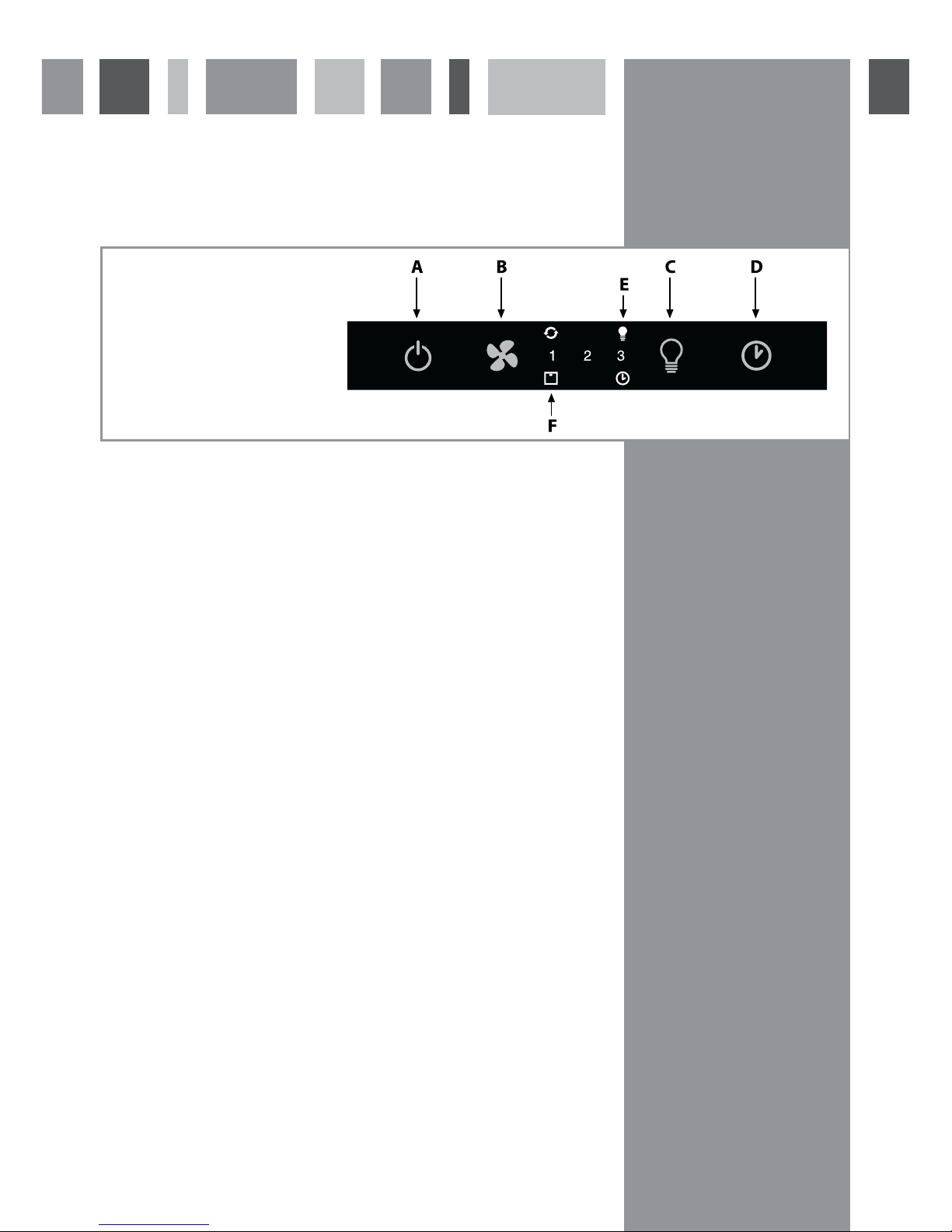
Control Panel
A – Power key
B – Speed level key
C – Light key
D - Timer key
E – Light indicator
F – Filters indicator
To switch on the extractor and set the speed level
• Touch key A. The appliance will switch on at the rst speed level.
• To increase the speed level touch key B. The speed cycles through rst, second and third speed levels, and the
relevant number indicator will show on the centre of the display.
• To switch the extractor o, touch key A.
The extractor lights
• To switch the lights on touch key C. The extractor lights will cycle through three light settings (high, medium, low,
o) with each touch of the key. The light indicator will show on the centre of the display when the lights are on.
The intensive function
• The extractor is equipped with an intensive function which runs for ten minutes before returning to the previous
selected speed level.
• To activate the intensive function, touch and hold key B at any speed level for approximately ve seconds. The 3
indicator on the centre of the display will ash whilst the intensive function is on.
• To cancel the intensive function, touch the speed level key and the extractor will return to the previous speed level.
The timer
• The extractor is equipped with a timer that allows the extractor to run for 15 minutes before switching
o automatically.
• To activate the timer, touch key D. The timer indicator will show on the centre of the display when the timer is on.
Please note
The timer cannot be activated when the intensive function is on.
The clean air function
• The extractor is equipped with a clean air function that switches on the motor for ten minutes every hour at speed
level one.
• To activate the clean air function, touch key A for ve seconds when the appliance is o. When the motor is running,
the light indicator will ash and the rst speed indicator will light up. For the remaining 50 minutes, the light
indicator will ash.
• To cancel the clean air function, touch any key except the light key.
Fig. 1
Page 4
3
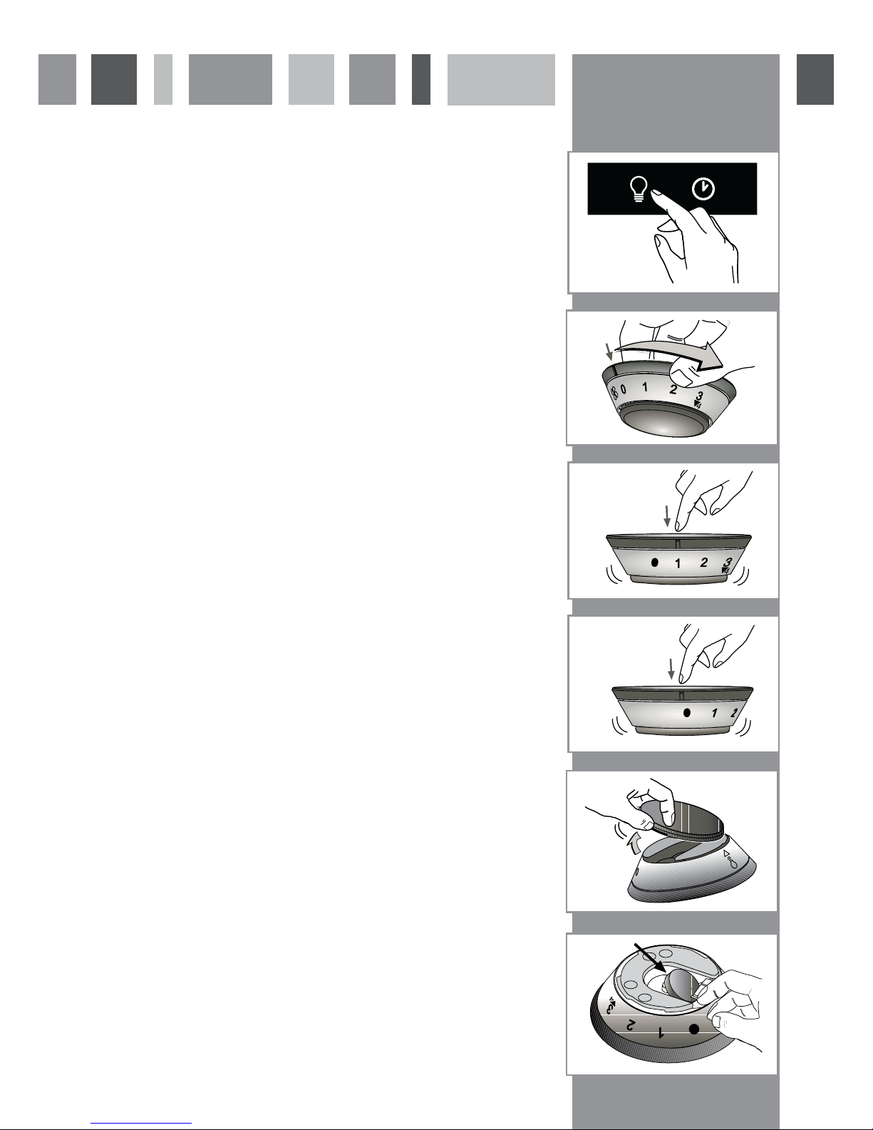
Using your Remote Control
Synchronising your remote with the extractor
1. Whilst the appliance is o, touch the light key on the extractor for
approximately ve seconds until the indicator light begins to ash, as
shown in gure 2.
2. Turn the top section of the remote control until the indicator light on
the extractor stops ashing.
In the event of any problems, repeat the steps above.
To set the motor speed
• Turn the top section of the remote control so the indicator is at the required
speed level, as shown in gure 3.
• To select the intensive speed level, press the remote control in for two
seconds at positions one, two or three, as shown in gure 4.
To turn on the light
• Press the remote control in to switch on the light to the highest level, as
shown in gure 5.
• To cycle through the light settings (high, medium, low, o ) press the remote
control in repeatedly.
To change the battery
• The battery will last for approximately 12 months, depending on usage.
• To change the battery, remove the lid from the remote control, as shown in
gure 6.
• Then remove the battery by applying pressure to the edge, as shown in
gure 7.
• Replace with a 3 Volt 5004LC / CR 2032 battery.
Please note:
The remote control will work up to ve metres away from the extractor.
The base of the remote control is magnetic so can be attached to ferrous
surfaces.
Fig. 2
2 sec.
Fig. 3
Fig. 4
Fig. 5
Fig. 6
Fig. 7
Page 5
4
Care and Maintenance
IMPORTANT : DO NOT PERFORM MAINTENANCE OR CLEANING OF THE
EXTRACTOR WITHOUT FIRST SWITCHING OFF THE ELECTRICITY SUPPLY.
Cleaning
You should use a nonabrasive cleaner. Any abrasive cleaner (including Cif) will
scratch the surface and could erase the control panel markings.
You can clean your extractor eectively by simply using a dilute solution of water
and mild detergent and drying to a shine with a clean cloth.
Cleaning the grease lter
The grease lter should be kept clean to minimise the risk of re.
After 30 hours of use, the lters indicator light will switch on to indicate that the
grease lters must be washed. you should remove and clean the grease lter with
hot soapy water. You can also wash the grease lter in a dishwasher, ensuring that
you place it in an upright position to prevent damage from other items in the
dishwasher. After rinsing and drying, replace the lter. After the grease lter has
been replaced, the electronic memory must be reset by touching the speed level
key for approximately ve seconds, until the lters indicator light switches o.
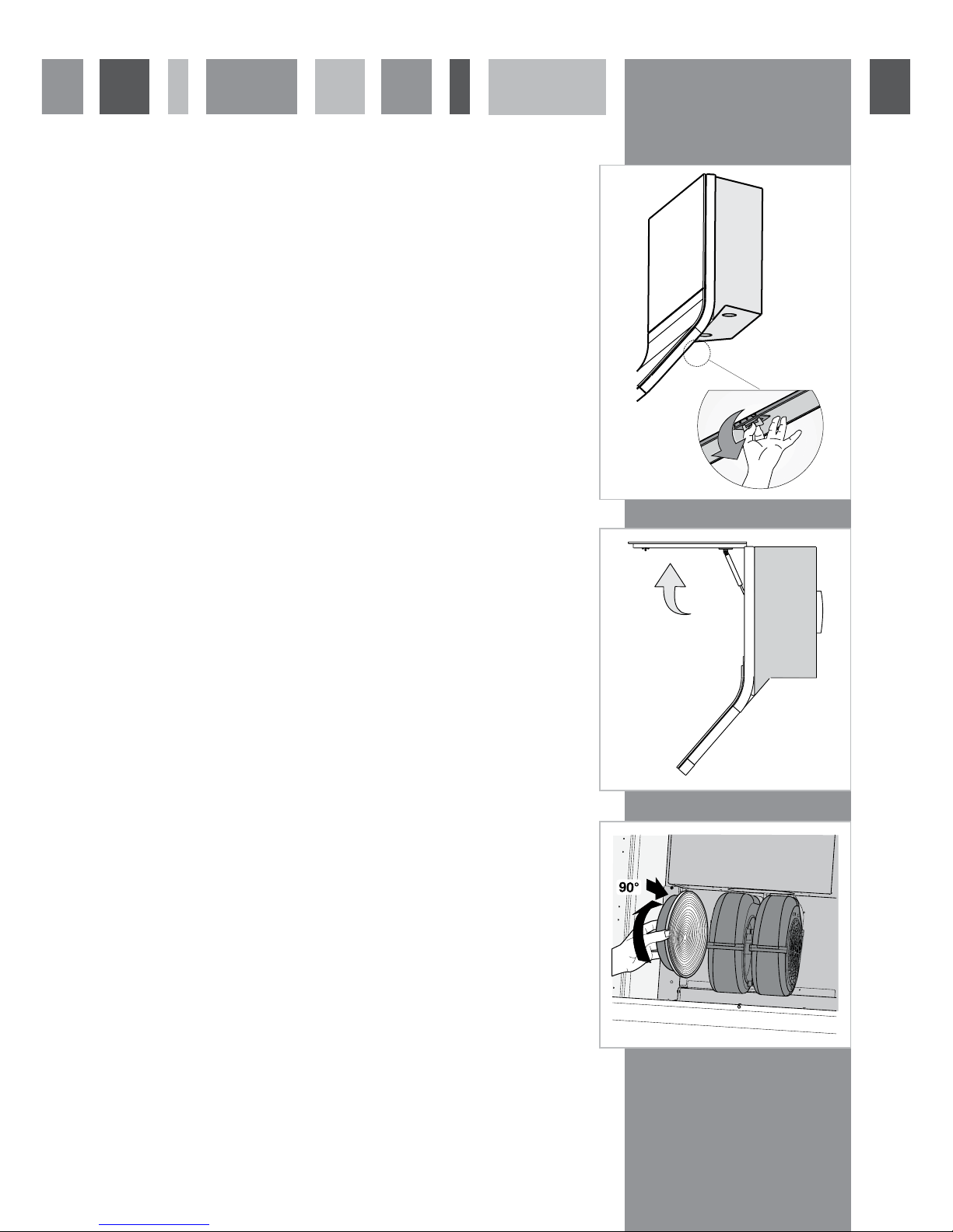
To remove the grease lter follow the steps below:
Pull open the handle on the grease lter as shown in g. 8. It will release at
the handle side. Then lower the grease lter to remove it completely.
To replace the grease lter, repeat the steps in reverse.
Please note:
Cleaning the grease lter in the dishwasher may lead to discolouration. This is
normal and does not constitute a fault with the appliance.
Changing the charcoal lter (re-circulating only)
After 120 hours of use, the lters indicator light will ash to indicate that the
charcoal lters must be replaced (if present). After the charcoal lter has been
replaced, the electronic memory must be reset by touching the speed level key for
approximately ve seconds, until the lters indicator light switches o.
To attach a new charcoal lter, rst open the cover panel as shown in gure 8.
Then oer up the charcoal lter to the side of the motor as shown in gure 4 and
turn it clockwise until it locks into place. Repeat with the other charcoal lter on
the other side of the motor. Then close the cover panel.
Fig. 8
Fig. 9
Fig. 10
2
Page 6

5
Changing the Light
IMPORTANT: DO NOT PERFORM MAINTENANCE OR CLEANING OF THE
EXTRACTOR WITHOUT FIRST SWITCHING OFF THE ELECTRICITY SUPPLY.
DO NOT CHANGE THE LIGHT BULB IMMEDIATELY AFTER USE AS THE
BULB WILL BE HOT. ALLOW IT TO COOL BEFORE REMOVING IT.
Carefully prise the bulb from the extractor using a small, at-bladed screwdriver.
Ret the new bulb taking care not to touch the glass (Fingerprints will lead to
premature failure of the bulb).
Do not touch bulbs or adjacent areas during or straight after prolonged use of
the lights.
The light is designed for use during cooking and not for general room illumination.
Extended use of the light can reduce the life span of the bulb.
Bulb replacement is not covered by the guarantee.
Only use bulbs recommended for your extractor. Do not t bulbs of a higher
power rating.
Bulbs of a lower power rating may be adequate for use, generally last longer and
use less energy.
Fig. 11
Page 7

6
DOUBLE POLE SWITCHED
FUSE SPUR OUTLET
USE A 3 AMP FUSE
Mains Electricity Connection
THIS APPLIANCE MUST BE CONNECTED TO THE MAINS SUPPLY BY A COMPETENT PERSON, USING FIXED
WIRING VIA A DOUBLE POLE SWITCHED FUSE SPUR OUTLET AND PROTECTED BY A 3A FUSE.
We recommend that the appliance is connected by a qualied electrician, who is a member of the N.I.C.E.I.C. and who will
comply with the I.E.E. and local regulations.
The wires in the mains lead of this appliance are coloured in accordance with the following code:
Green & Yellow = Earth, Blue = Neutral, Brown = Live.
As the colours of the wires in the mains lead for the appliance may not correspond
with the coloured markings identifying the terminals connecting to the fuse spur,
proceed as follows:
• The wire which is coloured green and yellow must be connected to the
terminal marked E (Earth) or coloured green.
• The wire which is coloured blue must be connected to the terminal marked
N (Neutral), or coloured black.
• The wire which is coloured brown must be connected to the terminal marked
L (Live), or coloured red.
Note: Use a 3A Fuse
Assembly and electrical connection should be carried out by specialised personnel.
When installing this product we recommend you seek the help of another individual.
Electrical Information
Mains electrical voltage: 230 – 240Vac, 50Hz
Total rated power consumption:
290W
Troubleshooting
If your extractor is not working:
1. Check that the mains supply has not been switched o.
2. Check that the fuse in the spur has not blown.
Page 8

7
Installation
Your extractor can be used to lter and recycle the air within
your kitchen, or to extract the air outside. When extracting air
to the outside, the unit can be vented as shown in the diagram
below. Note that we recommend the use of ducting with a
diameter of 150mm. Ducting with diameters of 100mm or
120mm may be used, but performance will be reduced.
Note that this product is heavy and should be installed
by two persons
The clearance between the underside of the extractor and
any hob underneath must be equal to or exceed 750mm (For
electric hobs, this height can be reduced to 650mm, but is
not recommended)
IN THE ABSENCE OF ANY INSTRUCTIONS SUPPLIED
WITH THE HOB, THE MINIMUM DISTANCE BETWEEN
THE HOB AND EXTRACTOR MUST BE AT LEAST 760mm
Fitting your extractor to the wall:
Before commencing, remove both the grease lters as shown
in gure 8 and the top cover (Fig 13).
Fig. 12
Fig. 13
750mm
Page 9

8
Installation
Remove the top cover (E) and vent outlet (M), as shown in
gure 15.
Using the provided template mark the positions of the
four xing holes on the wall, taking care to ensure that
the bottom of the extractor is at least the same or greater
than the clearance distance needed between the hob and
extractor.
The wall plugs used must be suitable for the type of wall
the extractor is to be xed to. Insert the four plugs and x
two screws (K) into the upper plugs, leaving approx 5mm
protruding.
Carefully lift the extractor and mount it on the two screws
and secure them tightly.
Fig. 16
Fig. 15
Fig. 17
Page 10

Fig. 19
9
Installation
Lift open the front top panel, as shown in gure 18.
Fit the remaining two screws to secure the extractor to the
wall.
Note that
it is recommended that you support the extractor until the
unit is secured to the wall.
Fig. 18
Page 11

10
Using the extractor as a
recirculation device
Ret the top cover and grill as below before proceeding to
t the charcoal lter – Locate each lter onto the motor
housing spigot and rotate to lock into position as shown in
gure 20.
Using the extractor as an
extraction device
Feed the duct pipe through the top cover and x it to the
duct adapter ring. Connect the ring to the extractor and
ret the top cover panel. Note that charcoal lters are not
required when the unit is to be operating in this manner.
Fig. 21
Fig. 20
Page 12

Page 13

Page 14

Page 15

Attribute Symbol Value Units
Model Identification 3c9
Annual Energy Consumption AEC
Hood
95.4 kWh
Time increase factor f 1.4
Fluid Dynamic Efficiency FDE
Hood
16.7 (D)
Energy Efficiency Index EEI
Hood
87.8 (D)
Measured airflow at Best Efficiency
Point
Q
BEP
294.3
m
3
/h
Measured Pressure at Best Efficiency
Point
P
BEP
265.0 Pa
Maximum airflow Q
MAX
362.0
m
3
/h
Measured electric power at Best
Efficiency Point
W
BEP
129.7 W
Nominal lighting power WL 40.0 W
Average illumination of the lighting
system on the cooking surface
E
Middle
200.0 Lux
Measured power consumption in
standby
P
S
1.0 W
Measured power consumption off
mode
P
O
NA W
Sound power level L
WA
52.0 dBA
Grease Filter Efficiency GFE
Hood
45 (G) %
Lamp efficiency LE
Hood
5 (F) %
Energy Efficiency Information
E & O E. All instructions, dimensions and illustrations are provided for guidance only. CDA reserve the
right to change specifications without prior notice.
Page 16

Customer Care Department • The Group Ltd. • Harby Road • Langar • Nottinghamshire • NG13 9HY
T : 01949 862 012 F : 01949 862 003 E : customer.care@cda.eu W : www.cda.eu
To contact our Customer Care Department, or for Service,
please contact us on the details below.
 Loading...