

Page 1
User Manual
Page 2

User Manual
CONTENTS
Chapter 1: DVR Features...................................................................................................................................................... 2
Chapter 2:Layoutt................................................................................................................................................................. 3
2.1 Front Panel.......................................................................................................................................................................3
2.1.1 4-CH Front Panel (Details please refer to the real product).................................................................................... 3
2.1.2 8-CH Front Panel (Details please refer to the real product).................................................................................... 4
2.2 Rear Panel.........................................................................................................................................................................5
2.2.1 4-CH Rear Panel (Details please refer to the real product).....................................................................................5
2.2.2 8-CH Rear Panel (Details please refer to the real product).....................................................................................6
2.3 Remote Control................................................................................................................................................................. 7
Chapter 3: DVR Installation ...............................................................................................................................................8
3.1 Hard Drive Installation..................................................................................................................................................... 8
3.2 Camera and Monitor Connection ..................................................................................................................................... 8
3.3 Power Supply connection..................................................................................................................................................8
Chapter 4: DVR Boot up ....................................................................................................................................................... 9
4.1 System Initialization..........................................................................................................................................................9
4.2 Main Interface................................................................................................................................................................... 9
Chapter 5: DVR Menu............................................................................................................................................................9
5.1 Main Menu Preview........................................................................................................................................................10
5.2 Main Menu......................................................................................................................................................................10
5.2.1 Camera setup .......................................................................................................................................................11
5.2.2 Record setup......................................................................................................................................................... 11
5.2.3 Network Set........................................................................................................................................................... 12
5.2.4 Recording Search.................................................................................................................................................14
5.2.5 Multi player ............................................................................................................................................................15
5.2.6 Device Management............................................................................................................................................16
5.2.6.1 HDD Management............................................................................................................................................ 17
5.2.6.2 Alarm Set .......................................................................................................................................................... 17
Email Alarm Notification.............................................................................................................................................. 18
5.2.6.3 PTZ Setup.........................................................................................................................................................19
5.2.6.4 Mobile............................................................................................................................................................... 19
Mobile Phone Access.................................................................................................................................................... 19
5.2.6.5 Motion Detect...................................................................................................................................................23
5.2.7 System Function................................................................................................................................................... 23
5.2.7.1 Tim e Set............................................................................................................... .............................................23
5.2.7.2 Password...........................................................................................................................................................24
5.2.7.3 V ideo Setup....................................................................................................................................................... 24
Page 3

User Manual
5.2.7.4 Language...........................................................................................................................................................24
5.2.7.5 Info....................................................................................................................................................................24
5.2.7.6 System Maintenance.........................................................................................................................................25
5.3 Menu Lock....................................................................................................................................................................... 25
5.4 V ideo Search.................................................................................................................................................................... 25
5.5 PTZ Control.................................................................................................................................................................... 25
5.6 Record.............................................................................................................................................................................26
5.7 Stop recording.................................................................................................................................................................26
Chapter 6: Net-Viewer Program........................................................................................................................................26
6.1 Plug-ins download and installation................................................................................................................................ 26
6.2 Log-in to NetViewer ........................................................................................................................................................ 26
6.3 Main Interface of Net-viewer.......................................................................................................................................... 27
6.3.1 Menu column.........................................................................................................................................................27
6.3.1.1 Live ................................................................................................................................................................... 27
6.3.1.2 Replay...............................................................................................................................................................27
6.3.1.3. Setup................................................................................................................................................................28
6.3.1.4 Log out.............................................................................................................................................................. 30
6.3.2 PTZ Control...........................................................................................................................................................30
6.3.3 Live Play Control ..................................................................................................................................................30
Chapter 7: Specifications...................................................................................................................................................31
Chapter 8: Windows Vista User ........................................................................................................................................32
Chapter 9: Appendix............................................................................................................................................................ 34
9.1 Operation Function Table...............................................................................................................................................34
9.2 Recording Alarm setting.................................................................................................................................................. 35
9.3 Troubleshooting............................................................................................................................................................... 35
9.4 Email server check list(The below info only for your ref.).........................................................................................36
9.5 Usage Maintenance......................................................................................................................................................... 36
9.6 System connection Configuration....................................................................................................................................37
Page 4

User Manual
1
Safety Instructions
1. Use proper power source.
Do not use this product with a power source that applies more than specified voltage (100-240V AC).
2. Never insert anything metallic into the DVR case.
Putting something into the DVR case can be a source of dangerous electric shock.
3. Do not operate in wet & dusty area or use near water.
Avoid places like a damp basement or dusty hallway.
4. Do not expose this product to rain or use near water.
If this product accidentally gets wet, unplug it and contact an authorized dealer immediately.
5. Keep product surfaces clean and dry.
To clean the outside case of the DVR, use a cloth lightly dampened with water (no solvents).
6. Provide proper ventilation.
This DVR has a built in fan that properly ventilates the system.
7. Do not attempt to remove the top cover.
If there are any unusual sounds or smells coming from the DVR, unplug it immediately and contact an
authorized dealer or service center.
8. Do not attempt to remove the top cover.
Warning: You may be subjected to severe electrical shock if you remove the cover of the DVR.
9. Handle DVR box carefully.
If you accidentally drop your DVR on any hard surface, it may cause a malfunction. If the DVR doesn’t
work properly due to physical damage, contact an authorized dealer for repair or exchange.
10. Use standard lithium cell battery. (NOTE: Manufacturer has preinstalled battery.)
The standard lithium cell 3v battery located on the mother board should be replaced if the time clock does
not hold its time after the power is turned off. Warning: unplug the DVR before replacing battery or you may
be subjected to severe electrical shock. Properly dispose of old batteries.
11. Make sure there is good air circulation around the unit.
This DVR system uses a hard drive for video storage, which generates heat during operation. Do not
block air holes (bottom, upper, sides and back) of the DVR that cool down the system while running. Install or
place this product in an area where there is good air circulation.
Page 5

User Manual
2
Chapter 1: DVR Features
Real time monitoring Supports real time surveillance via Monitor
Saves Recordings DVR saves real-time recording image to HDD
Backup Recordings Supports DVR backup via USB flash drive and hard drive.
Playback Recordings Supports DVR single CH and multiple CH playback of recorded files
Network operation Supports remote surveillance by multiple users simultaneously
Alarm Setting
Supports HDD & video input alarm management and external alarm signal
inputs
Mouse Operation Supports Mouse operation for faster menu navigation.
PTZ Control Supports PTZ camera operations through RS-485.
List 1-1
Other Features:
H. 264 video compression format, supports D1, HD1, CIF resolution
ADPCM audio compression format
Windows Graphical interface
BNC and VGA video out ports
Supports remote live viewing via 3G mobile networks
Supports sending email alerts when motion is detected by system
Triplex (recording, playback and net transmitting at the same time)
Supports USB mouse, IR remote control operation
Rear USB2.0 ports for backup, upgrade and mouse operation.
Supports Double Encode bit network transmission
The video package time is adjustable
Multiple alarm record mode
Multiple language OSD
Supports auto maintenance
Page 6
User Manual
3
Chapter 2:Layoutt
2.1 Front Panel
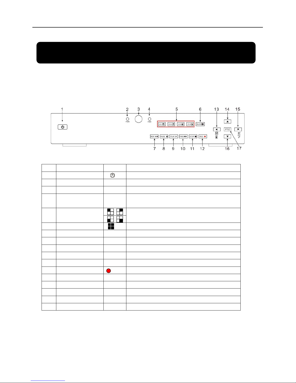
2.1.1 4-CH Front Panel (Details please refer to the real product)
Item Key title/Indicator Marks Functions
1
Power Switch
Turn Power on and off
2
Power indicator
PWR
If the “Green” indicator is on the system is getting power
3
IR Receiver
Receives signal from Remote Control
4
HDD indicator
HDD
When the “Red” indicator flashes it means the hard drive
is being read or written to.
5
Channel Select:
CH1 CH2 CH3 CH4
Select Single Channel Display
6
QUAD
Display all cameras in Live display or playback mode
7
REW
Move Left / Rewind
8
PAUSE
Pause / play frame by frame
9
PLAY
Enter into pop-up Menu/Play
10
FWD
Move Right / Play Forward
11
STOP
Stop Playback; stop manual recording
12
REC
Start Manual recording
13
MENU/ESC
Enter into main menu or exit menu
14
Up
Move Up
15
SEL/EDIT
Enter into pop up menu; Select key / Edit
16
Down
Move Down
17
PTZ:
Move to PTZ control mode
List 2-1
Page 7
User Manual
4
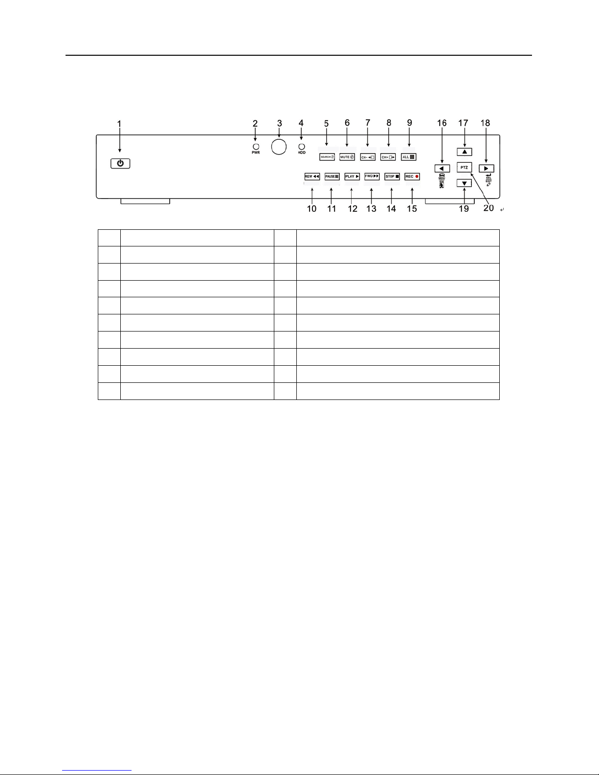
2.1.2 8-CH Front Panel (Details please refer to the real product)
1
Power Switch 11 PAUSE: Pause / Frame Play
2
PWR: PWR Indicator 12 PLAY: Play
3
IR receiver for Remote Control 13 FWD: Play Forward / Move Right
4
HDD: HDD Indicator 14 STOP: Stop Playback; Stop manual Recording
5
SEARCH: Recording Search 15 REC: Manual Recording
6
MUTE: Audio Mute key 16 MENU/ESC: Menu / Escape
7
CH-: Switch to previous channel 17 UP: Move Up
8
CH+: Switch to next channel 18 SEL/EDIT: Select / Edit
9
ALL: Preview all channels 19 DOWN: Move Down
10
REW: Rewind / Move Left 20 PTZ: Move to PTZ control mode
Page 8

User Manual
5
2.2 Rear Panel
2.2.1 4-CH Rear Panel
(Details please refer to the real product)
Item Physical port Connection method
1 Video input
Connect CH1-4 ( BNC interface)
2 Video output Connect monitor output ( BNC interface)
3 Audio inp ut Connect CH1-4 audio signal input (RCA interface)
4 Audio output Connect signal output (RCA interface)
5 Ethernet: Port Connect intranet, internet (RJ45 interface)
6 VGA Port Connect to VGA monitor
7 USB Port Connect USB device (Flash Drive, Hard Drive)
8 USB Port
Connect USB mouse
9 RS-485/Sensor/Alarm RS485/Sensor/Alarm interface (see pin outs below)
10 Power Port Connect power supply - DC12V 3A
Page 9
User Manual
6
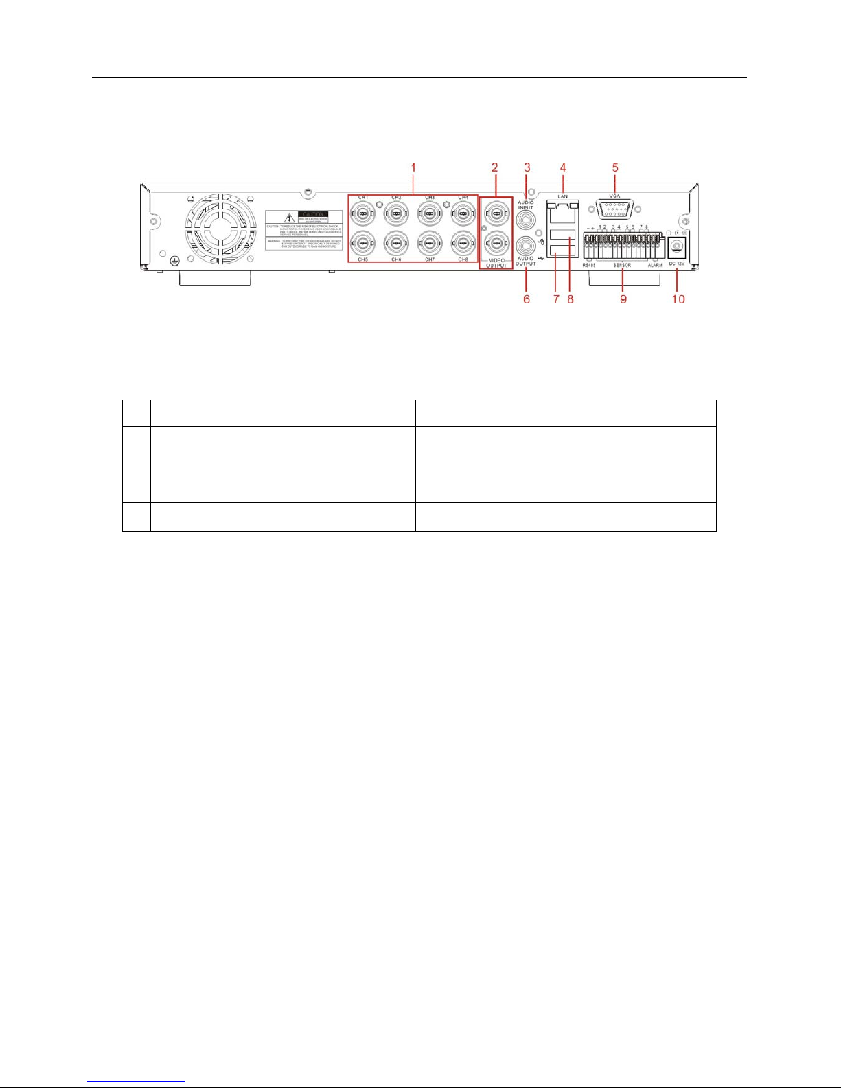
2.2.2 8-CH Rear Panel (Details please refer to the real product)
1 CH1-8: Video inputs 6 Audio Output
2 Video Outputs 7 USB port: backup to Flash Drive & Hard Drive
3 Audio Input 8 Mouse port
4 LAN: LAN port for Network Access 9 RS-485/Sensor / Alarm port
5 VGA port 10 Connect power supply
4-CH: RS485/Sensor/Alarm port
functions (from left to right):
Pin 1-2:PTZ Control port
Pin 1:RS-485A
Pin 2:RS-485B
Pin 3-4: Sensor 1 input
Pin 5-6: Sensor 2 input
Pin 7-8: Sensor 3 input
Pin 9-10:Sensor 4 input
Pin 11-12:Alarm Output
8-CH: RS485/Sensor/Alarm port functions
(from left to right):
Pin 1-2:PTZ Control port
Pin 1:RS-485A / Pin 2:RS-485B
Pin 3-4:Sensor 1 input
Pin 4-5:Sensor 2 input
Pin 6-7:Sensor 3 input
Pin 7-8:Sensor 4 input
Pin 9-10:Sensor 5 input
Pin 10-11:Sensor 6 input
Pin 12-13:Sensor 7 input
Pin 13-14:Sensor 8 input
Pin 15-16:Alarm Output
Page 10

User Manual
7
2.3 Remote Control
Mouse Operation
You can use a mouse instead of front panel buttons or remote control.
In menu lock mode, Enter into pop-up menu and clicking any sub menu to pop up Log-in
window; on menu unlock mode, enter into pop-up menu, and then clicking left key to
enter into any sub menu directly.
After entering main menu, clicking left key could enter into any sub menu; On[Detailed
file] menu mode, clicking left key could playback one recording file.
Change the status of check box and motion detection area.
Clicking combo box to access pull-down menu
By clicking left key you can adjust Color control bar and volume control bar.
By clicking left key you can select values in edit boxes or pull-down menu and supports
Chinese word input, special symbol, numeric and character input, use instead of
[Enter- ] or [Backspace
]
Click left key of
Mouse
In the [Detailed file] menu mode, clicking left key will playback one recording file.
In live display mode, clicking right key will display pop-up menu (shown as Picture 5-1).
Click right key of
Mouse
In Main menu or sub menu mode, clicking right key will exit current menu.
Double-click Left
key of Mouse
In live display or playback mode, double-clicking left key will maximize the screen.
Moving Mouse Select menu item
Sliding Mouse On motion mode, sliding mouse will select motion area; On [Color set] menu mode,
sliding mouse will adjust color control bar and volume control bar.
List 2-3
1 1-8
Channel Select 1-8 ; Numeric key
2
9、0
Numeric Key
3 ALL
Preview all Channel
4 Menu
Enter/Exit Main Menu
5 ▲
Up Key
6
▼ Down Key
7
◄ /
Left / Right Key
8 SEL
Select Key/ Edit Key
9
Rewind key
10
Play Key, Enter to recording search menu
11
Forward Key
12
●
Manual Recording
13
Pause / Frame Play
14
■
Stop manual recording; Stop Playback
15 Audio
Undefined
16 Mute
Undefined
Page 11

User Manual
8
Chapter 3: DVR Installation
3.1 Hard Drive Installation
Caution: Please do not Install or take out hard drive when DVR is running!
(1) Remove screws and open DVR upper cover carefully;
(2) Insert Power Cord and data cable into Pin of hard drive securely;
(3) Put the upper cover back carefully, re-attach screws.
3.2 Camera and Monitor Connection
Connect camera cable to video input of DVR, and from video output of DVR to Monitor via BNC
connector (Refer to section2.2-Rear Panel); or
If the camera is a PTZ speed dome, you could connect RS485 A & B to the according port of DVR
respectively (refer to system figuration on Chapter 8).
3.3 Power Supply connection
Please only use the power adapter supplied with the DVR .
Page 12
User Manual
9
Chapter 4: DVR Boot up
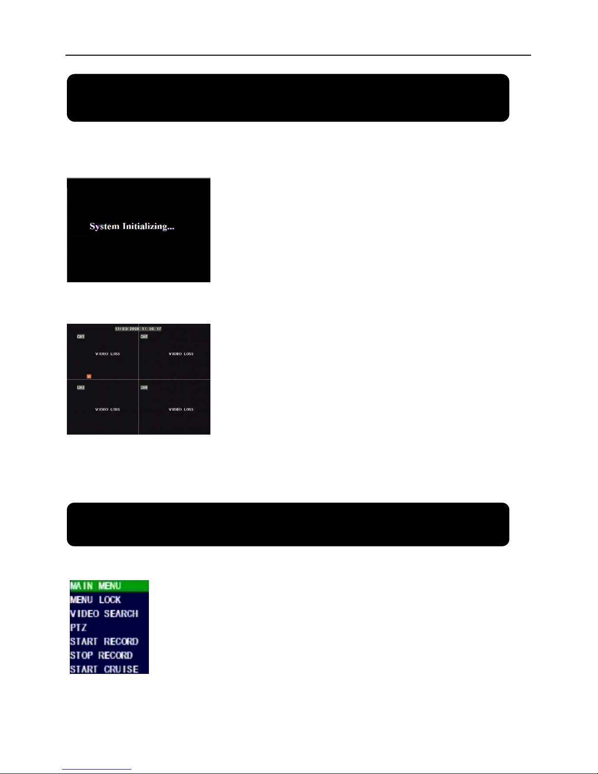
4.1 System Initialization
4.2 Main Interface
Chapter 5: DVR Menu
Pop-up Menu
After finishing system initialization, click right key of mouse on main
interface mode to enter into Pop-up Menu. Now you could proceed parameter
setting and operate for Main Menu, Menu Lock, Video Search, PTZ, Start
record, Stop Record and also operate for Start Cruise after successful PTZ
parameter setting etc.
After connecting the power adapter and turning
On the power button, the system will boot-up and start
initializing.
After finishing system initialization the system will enter into main
interface. Picture 4-2 is the main interface displayed by system, which
is showing no video input status. Once there are video inputs, the
interface will display live images from the cameras. In main interface
mode, if you use the mouse to double-click the live image of any
channel, the image will be maximized to full screen, by double-clicking
again, the display will be come back to quad mode displaying all
cameras; clicking the right button of the mouse, will enter into Pop-up
Menu; by clicking the left button of the mouse, you select menu items;
when clicking any area outside the menu, you will exit the Pop-up
menu.
Picture 4-1
Picture 4-2
Picture 5-1
Page 13
User Manual
10
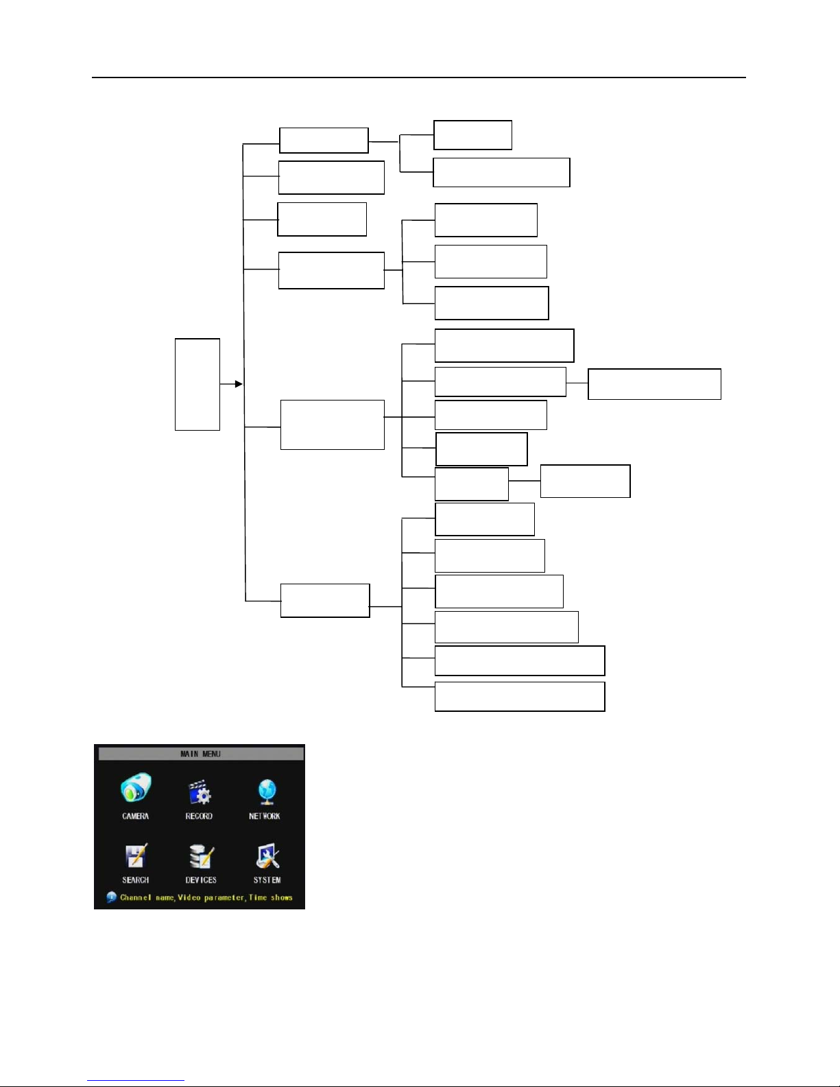
5.1 Main Menu Preview
5.2 Main Menu
Audio/Video setting, Language select, and access system information, system maintenance etc.
After clicking right button of mouse, pop-up menu will be displayed
on the screen. You can click [main menu] button on pop-up menu
to enter into Main menu interface (Shown as Picture 5-2). You can
also use the Menu button on the front panel to bring up the window,
when using the front panel buttons use the FWD and REW button
to move in the menu, and the SEL button to select the icon. You
use the ESC button to return to previous window. In Main Menu
mode, you can control device management settings, such as
Camera, Recording, Network, Recording search, HDD, Alarm, PTZ
Control, Mobile Phone & motion detection etc, you can also set
system function settings, such as Time setting, User password,
Picture 5-2
Main Menu
Rec. Search
Search
Playback
File List
Recording
HDD Management
Alarm Setting
PTZ Setting
Mobile
Motion
Color set
System
User password
System Information
Language Select
System Maintenance
Video Setting
Time Setting
Device
Management
Network
Area setting
E-mail setting
Dwell time display
Page 14
User Manual
11
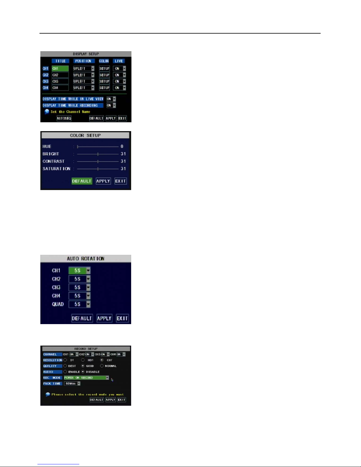
5.2.1 Camera setup
Explanation:
1、The modifications will be available after clicking [APPLY] button on the bottom of the sub-menu windows
and being prompted to save and then clicking [ok] button.
2、If you want to cancel the modification, click [Exit] button to exit the menu.
3、When clicking [DEFAULT] button, all system default values will be reset to default value.
4、System default value indicates the value pre-set at the factory.
5.2.2 Record setup
Go to [Main Menu Camera] to set up the name display
and position display of each channel (Shown as Picture 5-3), You
can also adjust image brightness, saturation, contrast and hue
settings of each channel after entering into [Color] Menu and set
up whether each channel can be previewed or not under Live
display and/or Recording mode.
Please note that the name of each channel supports up to
eight characters or four Chinese characters.
Click [Main Menu] [Record] to enter into [Record Setup]
menu (Shown as Picture 5-5)
Functions:
1、The [Rec Mode] button allows you to setup recording 24
hours, on motion, or on a set schedule.
2、[PACK time] indicates maximum continuous time length of
recorded files (15, 30, 45, 60 min).
Below is the Color Menu where you can adjust image
brightness, saturation, contrast and hue parameters of each
channel.(shown as picture 5-4)
Picture 5-4
Picture 5-5
Picture 5-3
Click [AUTOSEQ] button to start auto rotation function.
(setting sub menu shown as Picture 5-4A. After starting auto
rotation function, system will auto rotate the video images among
CH1, CH2, CH3, CH4 and Quad in turn.
Default rotation time: 5 second
Settable time range: 0~10 second
Picture 5-4A
Page 15
User Manual
12
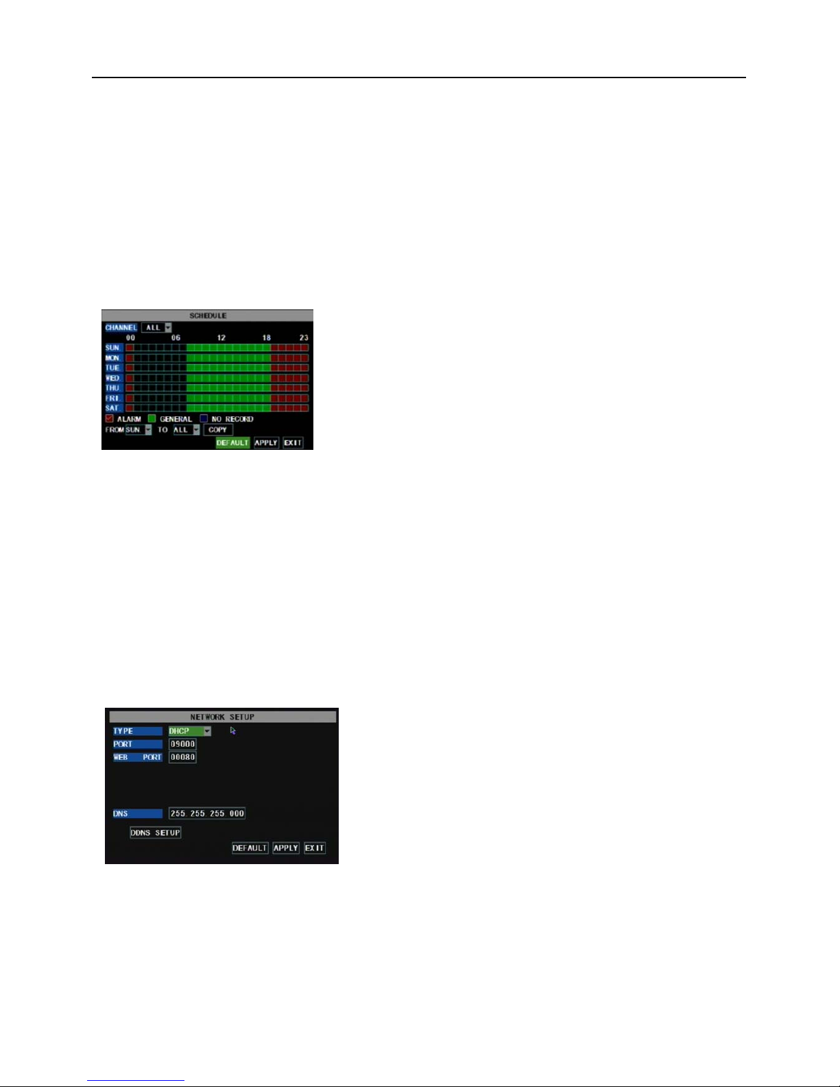
The [Record Setup] menu allows you set up recording status (on/off) of each channel, it also allows you
setup recording image resolution and quality, and turn audio on/off. This menu also allows you select
recording mode (recording after power on and scheduled recording) and recording file length.
Once a channel is set to “on” the channel can record, if it is set to “off” the video from the channel will not
be recorded. Resolution options are D1, HD1 and CIF; and Quality options are Best, Good and Normal.
When Audio is set to “On”, system will also record audio from the channels and will have audio output on
playback mode; if it is set to “off” you can not record audio and will have no audio output available on
playback mode.
To record 24 hours a day set the Rec Mode to Always. To record on motion or a set schedule, select
Time Schedule Record and click the “Schedule” option, the Schedule interface will open as shown in (picture
5-6):
complete the schedule you activate it by clicking the [Apply] button.
You can also click on the Default button to use the system defaults. The system default settings are:
Hr01:00 am-07:59 am : No recording
Hr08:00 am-18:59 pm : Normal recording
Hr 19:00 pm- 00:59 pm : Alarm recording
Explanation: Under the recording Set menu and recording search menu, original color stands for no
recording, “Red” stands for alarm recording, “Green” stands for normal recording and “Blue” stands for the
channel and date you have selected.
5.2.3 Network Set
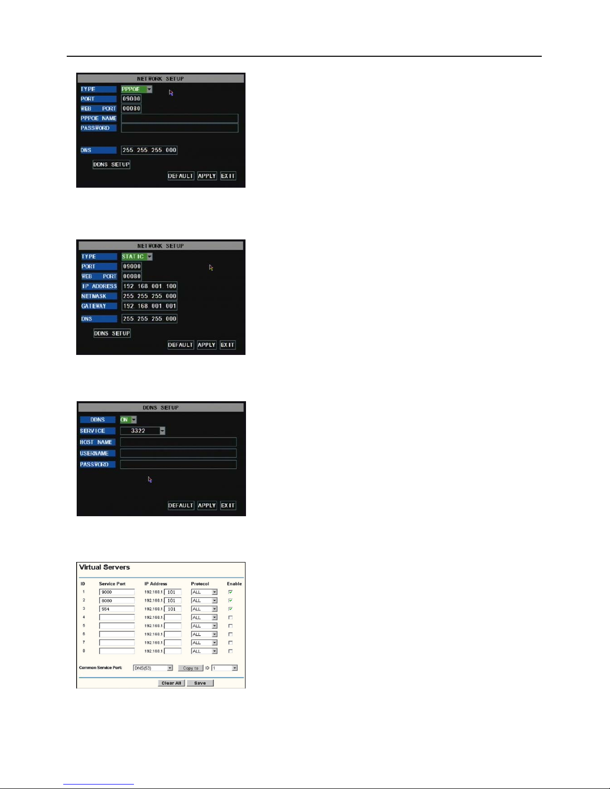
Enter into [Main MenuNetwork Set] to proceed network set (Shown as picture 5-7):
After selecting network mode - such as DHCP、PPPOE and
static allocation and setup web port, you could visit DVR remotely
via network.
Picture 5-7
Recording options include All, CH-1, CH-2, CH-3, CH-4
respectively. Please click the channel you need, the channel you
select will be highlighted in “Blue” unselected channels will be “Grey”.
To setup weekly schedules, click on the box of the recording
status you want (Alarm, General, or No Record) and then click on
each box in the schedule time line that you want this method to apply
to. You can use the [From – To] pull-down menus and Copy button to
copy settings from one day to another day or all days. After you
Picture 5-6
Page 16
User Manual
13
When selecting DHCP, DHCP server will allocate DVR IP address automatically.
Picture 5-9
Picture 5-8
When selecting PPPoE, you need to input user and password
provided by ISP supplier and set up web port (details please refer
to the below picture 5-8).
Picture 5-9
When selecting static allocation, you need to setup IP address,
net-mask, gateway and web port (shown as picture 5-9).
Picture 5-10
Picture 5-11
If you need to visit DVR via Internet, you should setup the
inflection of video port at the public Router located in the DVR
(shown as Picture 5-11).
Host Port: 9000
Web Port: 8080
LAN IP address of DVR: 192.168.1.101
Input http:// router IP:8080 (192.168.1.101:8080) to you
computer IE browser,then you will visit your DVR freely.
If you apply for DDNS service and set up net parameter of
DVR accordingly, you could visit DVR remotely via IE browser.
(shown as picture 5-10)
Page 17
User Manual
14
5.2.4 Recording Search
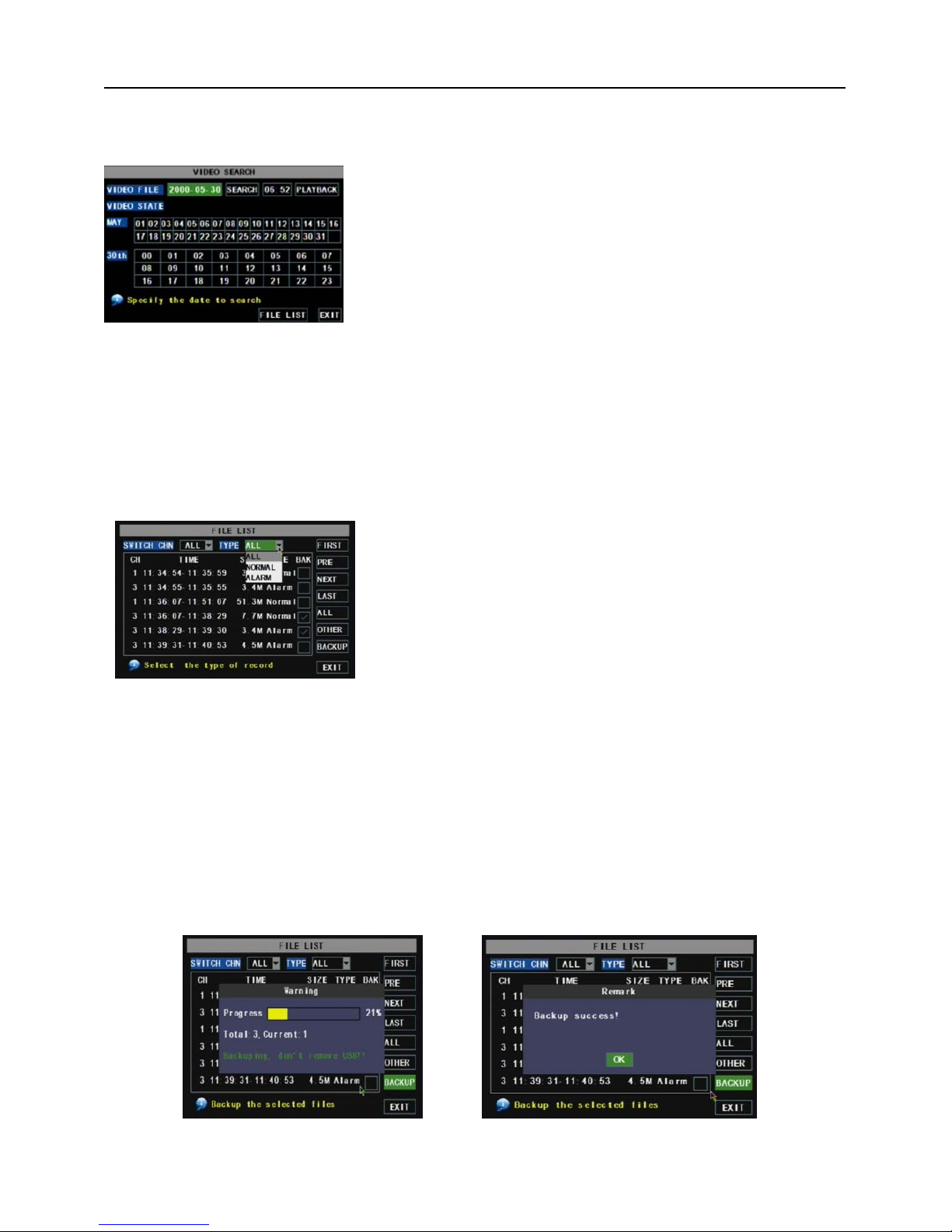
Click [Main menu search] to enter into [Video Search] menu (shown as the below picture 5-20).
You can play video Forward at 2x, 4x, and 8x speeds, Slow play at 1/2x, 1/4x, and 1/8x, normal play,
pause and play frame by frame using the playback control bar, and adjust volume by clicking or sliding tune
control bar. When playback has finished, system will return to previous menu.
File list
On the [Video search] menu mode, click [File list] to pop up the sub-menu shown below as Picture 5-21.
This option will allow you to view all of the available files by channel and type (all, normal, or alarm).
You can select a file and push the SEL button to playback the file, or use the FWD button and down button to
select the option and backup the recording file you selected. You can also put a checkmark in the box at the
end of multiple files if you want to backup more then one file.
LAST (Last page): Indicates the last page of recording history you have searched. When you view other
pages, clicking [Last page] button will take you to the Last page.
ALL (Select All): Allows you to select all the events on the current page.
INVERSE (Select Invert): Allows you to select other events on the current page except those you have
currently selected.
Recording File Backup
If you want to backup one recording from the file list, you just select the recording and click [Backup]
button. When the backup is completed you will be notified. Please click [OK] button to save your backup
(shown as Picture 5-22).
Explanation: Backup file will be in H264 format, you can convert it to AVI format using the Multimedia
Player program that comes with the DVR or through the net-viewer program, so you can use any player
which supports AVI format.
Searched playback:
If you input specific date and click [Search], you will find all the
recordings for that day. When you select [Date] item, you will
playback the recordings in 4 channel mode; or, click [File list] button
to display File list interface, where you can playback or backup the
file you selected. See File List heading below.
Picture 5-20
Picture 5-22
Picture 5-23
Picture 5-21
First:Indicates the first page of recording history you have
searched. When you view other pages, clicking [First] button brings
you back to Page one.
PRE (Previous page): When viewing event list, clicking
[Previous page] button will take you back to page before the one you
are currently viewing (except the first page).
NEXT (Next page): When viewing event list, clicking [Next page]
button will take you to the page after the one you are currently viewing
(except the last page).
Page 18
User Manual
15
5.2.5 Multi player
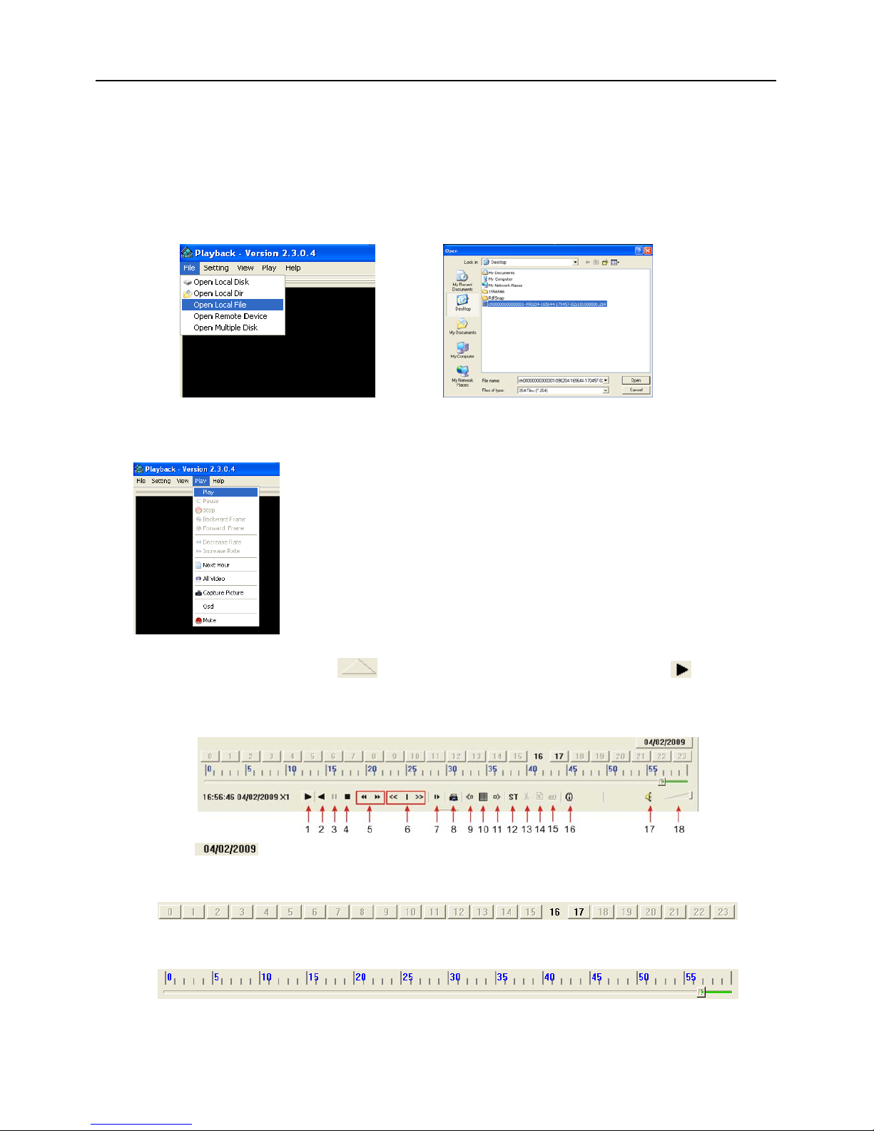
1、Copy backup file to your PC.
2、Open multimedia player and click [File Local (F)] to find/select the backup file, and then click [open]
button
Note: the file type you have selected should be *.264 format.
3、Open backup file:
(2)、Click pop-up menu button
on the bottom of multimedia player and [Play- ] button, then
the backup file will be played on the according channel.
(3)、The Menu brief on the bottom of multimedia player:
Date:
recording date for the current backup file shown as right corner;
24H recording time: lie under [Date] menu. Black number button stands for current recording
playback is normal recording for the time line.
0~60 Minute recording time quantum: Green part on play processing bar stand for recording length
for one hour recording.
(1)、Click [Play] menu (P) on the top of multimedia player
interface to select playing the backup file;
Picture 5-24
Picture 5-25
Picture 5-26
Page 19
User Manual
16
Recording date and time processing for the current recording file
1 Pla
y
10 All the windows
2 Previous recording file 11 Add window
3 Pause 12 Start
4 Stop 13 Cut
5 Previous frame / Next frame 14 Delete
6 Slow play, Normal play, Fast Pla
y
15 Convert AVI
7 Next Hour 16 OSD
8 Capture picture 17 Mute switch
9 Reduce window 18 Volume adjust
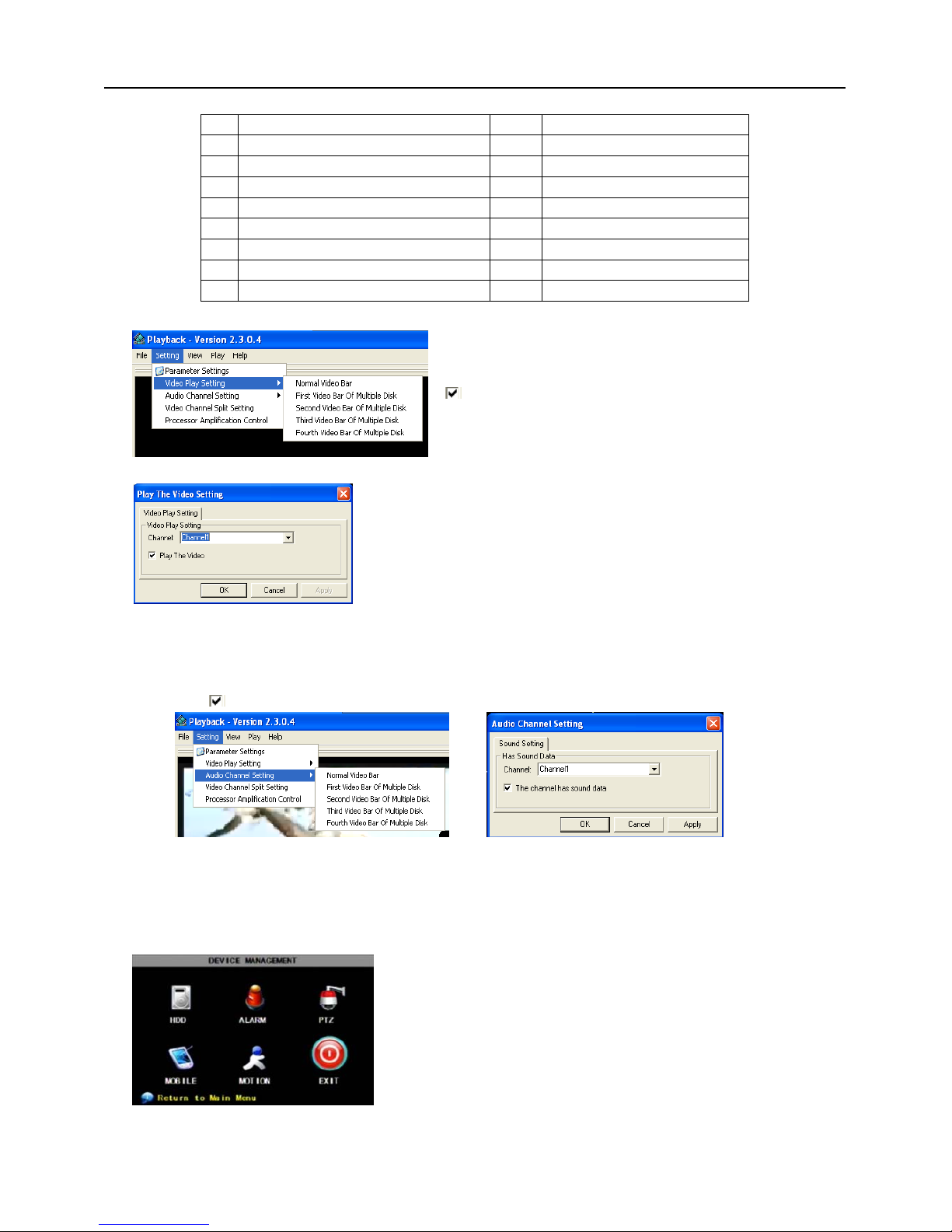
4、Please refer to the below [Video on] setting procedure (System default - video for every channel is on)
5、Refer to the below for [Audio on] setting procedure. (Setting parameter will be available after re-starting
multimedia player after [Audio on] set up.)
SettingAudio channel setting Normal video BarSelect the channel you want to playback the
audioSelect
the channel has audio filesApplyOK.
After successfully setting the above, when you playback the current channel, you can open the channel’s
audio function at the same time as the video
5.2.6 Device Management
SettingVideo play setting Normal video
BarSelect the channel you want to display Select
to play the videoApplyOK
Options in device management include Hard drive,
External Alarm, PTZ control, Mobile Phone Monitoring, and
Motion Detection.
Picture 5-27
Picture 5-27A
Picture 5-28A
Picture 5-28B
Picture 5-29
Page 20
User Manual
17
5.2.6.1 HDD Management
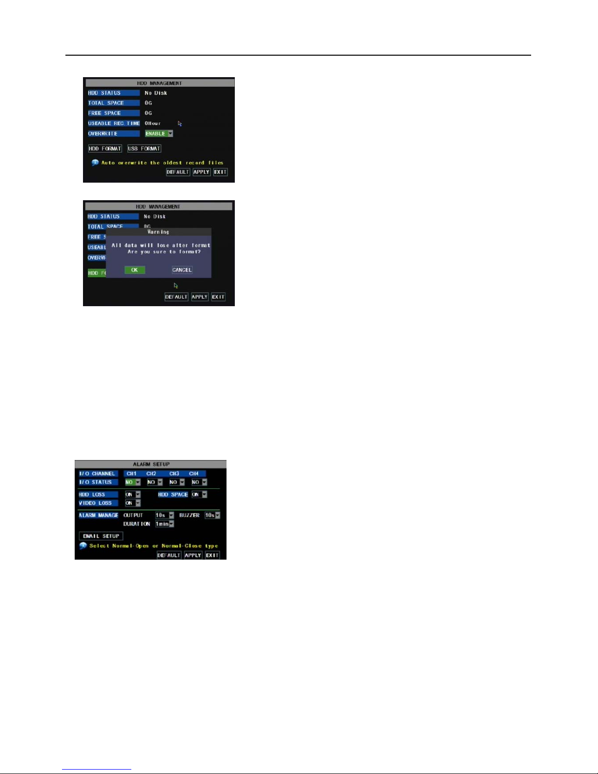
OVERWRITE: If you select “on” the system will automatically overwrite the oldest recordings once the
hard drive is full; if you select “off”, recording will stop once the hard drive is full.
HDD FORMAT: You use this option to format the hard drive, you can not record files to the hard drive
until it has been formatted. Click [Format HDD] button to start formatting. When selecting [Format HDD]
option the system will prompt you – “Format HDD will loss all the data, do you confirm?” ; click “OK”, system
will prompt you – “Is formatting…” and “successful format”; and then system will restart automatically.
USB FORMAT: Use this option to format USB devices.
5.2.6.2 Alarm Set
not external sensors to record on motion detection.
HDD LOSS: Options are On and Off. If you select On there will be a buzzer sound and “H” sign on screen
when HDD is not detected or not formatted; on the contrary, if you close the function, there is only “H” sign to
indicate HDD not found, but no alarm sound when HDD not found or not formatted.
HDD SPACE: Options are On and Off. When the alarm function is on, there are alarm sounds when the
HDD is running out of space; when the function is off, there are no alarm sounds.
VIDEO LOSS: Options are On and Off. When the function is on, system will issue alarm sound and
display video loss on the preview interface; when the function is off, system will have no alarm sound, but the
preview interface will display video loss.
ALARM MANAGE:Alarm Output(0s,10s,20s,40s,60s)、Buzzer time (0s,10s,20,40s,60s) and alarm
duration time(0s, 30s, 1minute,2minute,5minute)。
Click [Main MenuDevice HDD] to enter [HDD
Management] menu (shown as Picture 5-30)
Click [Main MenuDevice Alarm] to enter into [Alarm setup]
menu to setup Alarm warnings (shown as Picture 5-32).
I/O STATUS : Options include NO (Normal-open), NC
(Normal-close) and OFF. Set to “Normal-open” if you use external
sensor alarms that are normally open, Set to “Normal-close” if you
use external sensor alarms that are normally closed, set to “off” if you
are not going to use external sensor alarms. You can use the DVRs
internal motion detection to record when motion is detected; you do
Picture 5-32
When you install a HDD, the system will automatically detect
if HDD is formatted or not; If HDD needs to be formatted, HDD
status will be shown as “Not format”, otherwise, the HDD status
will be shown as “Normal” (refer to Picture 5-31)
TOTAL SPACE: Indicates total space available on Hard
Drive.
FREE SPACE: Indicates unused space available on the
Hard Drive.
USEABLE REC TIME: Based on current image
detail/quality and frame rate, system will show you how
Recording time you have left on the Hard Drive.
Picture 5-30
Picture 5-31
Page 21
User Manual
18
Alarm Type Function
Video Loss
Sends alarm when DVR can’t receive video signal (such as camera damage, cable broken or damaged
or power supply malfunction).
Motion Detection
When an object moves into motion detection area, alarm will be triggered. You can adjust
sensitivity level to suit the needs of your actual application environment.
I/O Status System can convert alarm signal triggered by external sensor into signal identified by system.
HDD loss
When Hard Drive is not detected (HDD damage, power supply malfunction), or HDD auto-overwrite
is off, and free space is not enough, an alarm will be triggered.
List 5-1
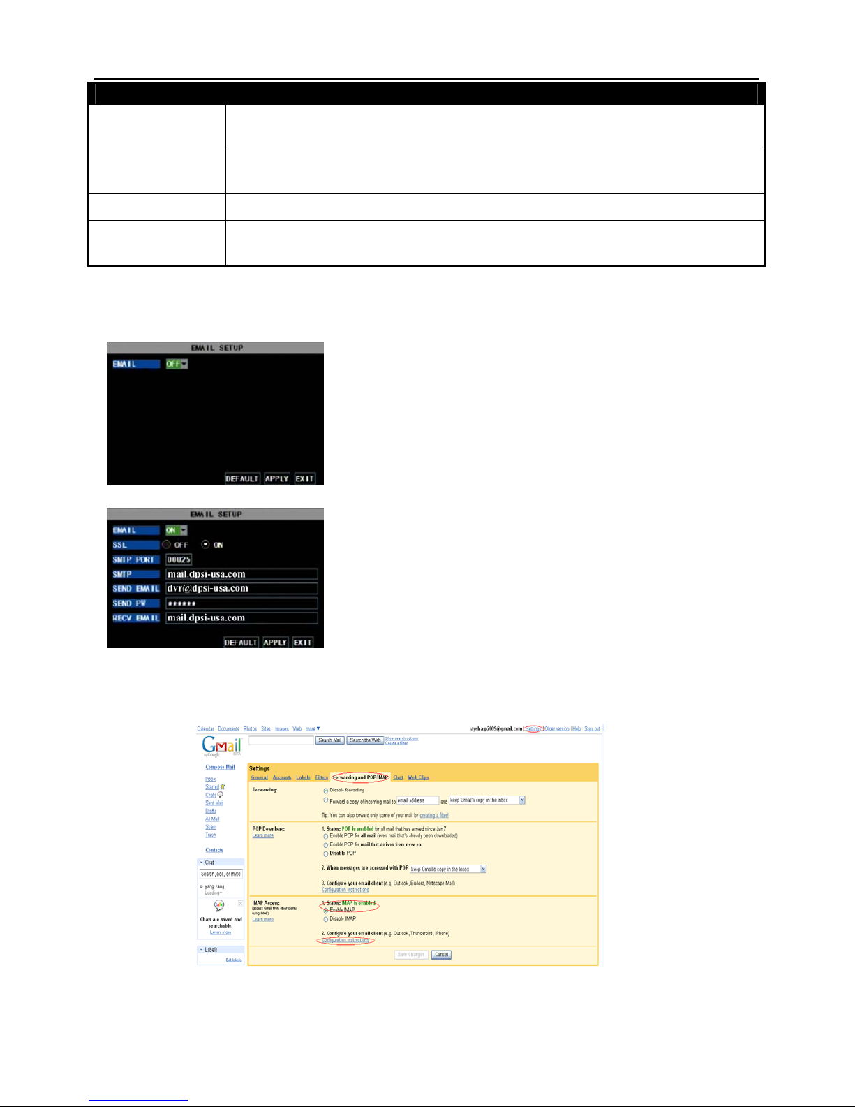
Email Alarm Notification
(to send notice to email account when motion alarm is triggered)
Please set SSL to “On” via Gmail.com server, and set to “Off” via other mail server.
If your setting is still not right, please contact the web site where you have applied for your email box to
get SMTP server and SSL of mail box.
SMTP Port: indicates sender port of SMTP server. Generally the SMTP port value is 25, but
Click the [Email setup] menu to enter into its sub menu
(shown as Picture 5-33).
Pi
cture 5
-33
On the [Email setup] mode, refer to its parameter setup
shown as picture 5-34 when setting email alarm to “on”.
SSL: is a security link transport protocol. You can encrypt your
communication info (including your email) using SSL to prevent hackers from
monitoring your email or communication info and even your password.
Pi
cture 5
-34
Picture 5-35
Page 22
User Manual
19
there are exceptions, for example, SMTP port of G-mail server should be 465.
SMTP server: indicates server address you use.
Sender email: indicates sender’s email address. The email address should be consistent with the server
you use. That is to say, when you use email address – [email protected]
, the according server should be
smtp.gmail.com.
Receiver address: indicates receiver’s email address. The email address is used to receive ima
ge transmitted from motion detection alarm of DVR. Please clear the images you have received as
soon as possible to avoid overloading your email account. For detailed SMTP protocols settings
refer to the below picture 5-35A.
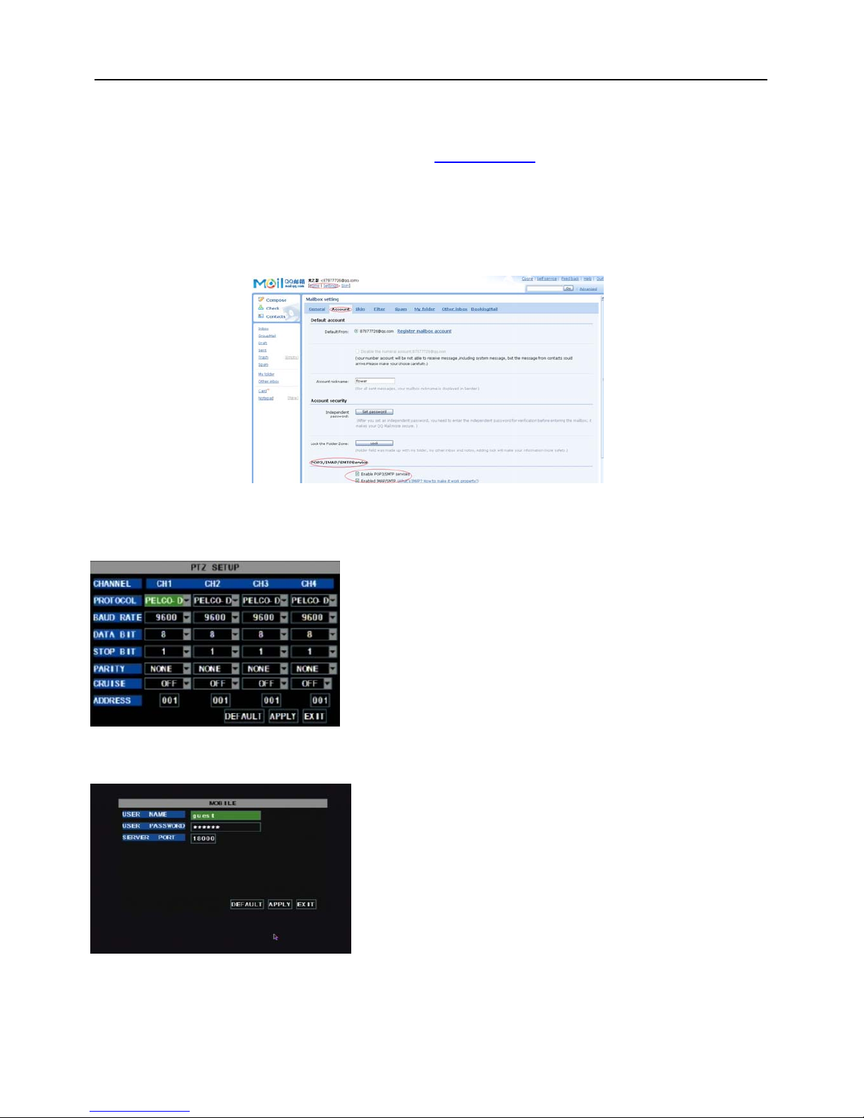
5.2.6.3 PTZ Setup
5.2.6.4 Mobile
Mobile Phone Access
The DVR is currently compatible with mobile phones running Windows Mobile and Symbian operating
Enter into [Main menuDevice PTZ Setup] to select
the channel you want to control and set PTZ protocol
(Pelco-D or Pelco-P), Baud Rate (1200, 2400, 4800, 9600),
Stop bit (1, 2), Parity Check (None, Odd, Even Mark Space),
Address Code and Cruise status respectively. Please note
the above mentioned channel settings must match the
settings of the PTZ camera.
Click [Main menuDeviceMobile] to enter into [Mobile]
menu.
User Name: indicate user name of DVR.
User password: indicate user password of DVR
Server port: Mobile monitoring port. Setting range is between
1024 and 65535. Please note that
Explanation: Please connect DVR to Internet before
setting DVR port number and the server port no is not equal to
network menus.
Picture 5-37
Picture 5-35A
Picture 5-36
Page 23
User Manual
20
systems on 3G networks.
Before you can access the DVR from a mobile phone you need to setup the Network Configuration on
the DVR. Go to section 5.2.3 Network Setup on page 14 of the product manual for instructions on how to do
this. You also need to go to the Main Menu then Devices then Mobile and enter your user name and
password, and set the Server Port to 18600. This port also needs to be forwarded to the IP address of the
DVR along with the ports from 5.2.3 Network Setup.
Explanation: You can only see one channel at a time when viewing from a mobile phone. The
speed of the display depends on the speed of the internet connection.
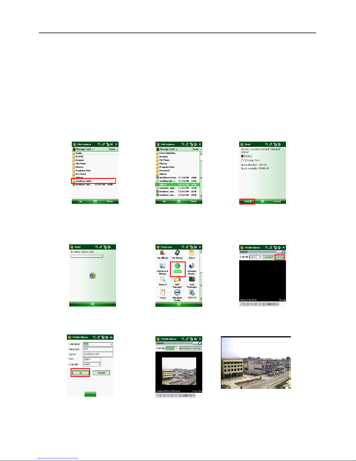
When accessing from a mobile phone with Windows Mobile operating system, use the following
procedure:
1. Webcam installation
First you need to install the webcam program that is included on the CD that comes with the DVR by
copying the “QQeye.CAB” file to the mobile phone. You can do this by attaching the mobile phone to a
computer and copying the file from the CD to the memory card on the phone, or by copying the file from the
computer to the phone’s memory card through a memory card reader or through a Bluetooth connection.
2. Click the windows mobile folder (red box in Pic 1) and choose the file
QQeye” Select the file which will open the window in Pic 3. The file is generally faulted to save as Device,
direct to phone, (shown in Pic 3) but you can save it to Device or Storage Card.
3. Choose storage location and click [Install] button (red box in Pic 3) to start the installation (please refer
to display in Pic 4 below)
4. After installation finishes, click the icon named QQeye (red box in Pic 5) to run the program. This will
display the program screen in Pic 6.
5. Settings: Click [Setting] button (red box in Pic 6) to enter the Setting menu shown as Pic 7
User name: same as user name setup in DVR under Menu, Devices, Mobile
Password: same as password setup in DVR under Menu, Devices, Mobile
Server address: Public IP address of router DVR is connected to.
Pic 7
Pic 8
Pic 9
Pic 4
Pic 5
Pic 6
Pic 2
Pic 3
Pic 1
Page 24
User Manual
21
Web port: Same as the Server Port you setup in the DVR, it needs to be forwarded to the IP address of
the DVR, setting range is between 1024 and 65535, the default setting is 18600. Note: this port is in addition
to the ports used for standard remote access.
Channel: Select the channel from the DVR you want to monitor and click [OK] button (red box in Pic 7) to
display the screen in Pic 8 and start video connection.
6. Main interface operation (Pic 8)
Click [Disconnect] button to stop displaying live image of the channel.
Click [Setting] button to modify the settings.
7. Video connection Display
Normal Mode:
You will find network connection status info under the video image:
Display on the left corner: Network transmission speed, Frame rate and Resolution.
Display on right corner: percentage of buffer display, Connection success,Connection fail, Play and Stop.
Function of Buttons under the video image from left to right: PTZ control (Left, Right, Up and
Down), area select (Zoom out and Zoom in), Focus (Add “+” and deduct “-”) and Iris (Add “+” and
deduct “-”) and Snap to capture screen image.
8. Display mode: You can convert normal display into full-screen display by clicking
the screen on the mobile phone (displayed as Pic 9)
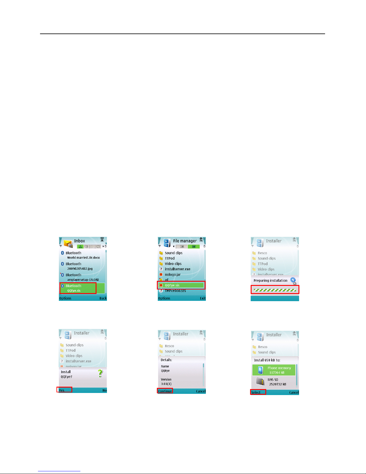
When accessing from a mobile phone with Symbian operating system, use the following
procedure:
1. First you need to copy the file with suffix “QQeye.CAB” that is included on the CD disk to the mobile
phone.
Copying file is save to storage card by default, and the file can also be transmitted from the CD through a
computer by Bluetooth technology to save to Inbox (Pic 1). Select the QQEye program (red box in Pic 1)
which will display Pic 2.
2. Select the QQEye icon in this window (red box in Pic 2) to install it, this will display Pic 3).
After the phone finishes preparation it will display Pic 4 asking for permission to install the program.
Select the Yes button (red box in Pic 4). This will display the window in Pic 5.
``
3. Click the Continue button (red box in Pic 5) on the information box displaying the program and current
version. This will display the window in Pic 6.
4. Next choose where you want to install the program, to phone memory or to the memory card, and click
Pic 4
Pic 5
Pic 6
Pic 2
Pic 3
Pic 1
Page 25
User Manual
22
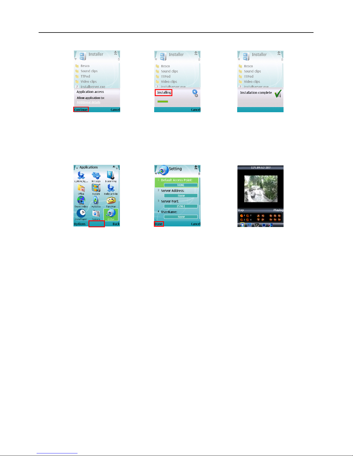
on the Select option (red box in Pic 6). This will display the window in Pic 7, click on Continue (red box in Pic
7) which will display the screen in Pic 8 and tell you it is installing the program (red box in Pic 8).
5. Once the installation is complete the window in Pic 9 will be displayed to tell you that installation is
completed. Then you can go to the Applications folder and select the QQEye program (white box in Pic 10)
and click on the Open option (red box in Pic 10) to display the settings menu. After you complete the settings
and click on the Done button (red box in Pic 11) the Video window in Pic 12 will be displayed.
Default Access Point:
Input the access point. System default for the access point is GPRS connection.
Server Address:
Input the public IP address of the router the DVR is attached to (refer to section 5.2.3 Network Setup on
page 14 of the product manual).
Server Port:
Web port: Same as the web port setting on the DVR, you need to forward this port from the Router to the
DVR. Setting range is between 1024 and 65535, the default setting is 18600. Note: this port is in addition to
the ports used for standard remote access.
User Name:
Same as user name setup in DVR under Menu, Devices, Mobile
Password:
Same as password setup on DVR. (Please press Function key to save the password, left soft key won’t be able
to save the password)
Channel:
Select the channel you want to monitor and click [OK] button to start video connection
Network connection status: percentage of buffer display, connection success, connection fail, play and
stop.
Channel select, PTZ control, Zoom in/out, Focus and Iris
Play/Stop, Full screen/ Normal Display, Capture, Parameter setting and Exit【】
By clicking on the image you can see it full screen as in Pic 13
Pic 7
Pic 8
Pic 9
Pic 11
Pic 12
Open
Pic 10
Page 26
User Manual
23
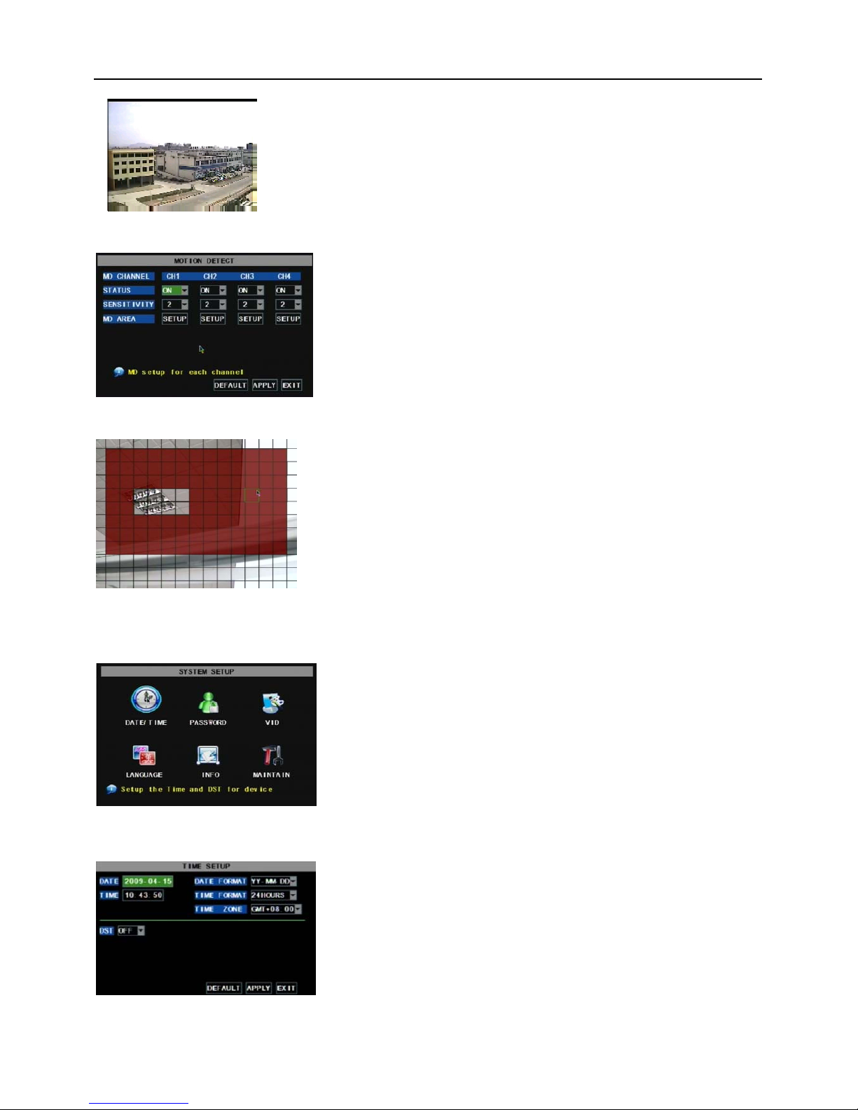
5.2.6.5 Motion Detect
5.2.7 System Function
5.2.7.1 Time Set
Click [MainDeviceMotion] to enter into the [Motion Detection]
menu to setup motion detection recording.
The [Motion detection] Menu has three sections, including
Channel Status, Sensitivity and Motion area.
Channel STATUS: This option allow you enable motion detection
on any channel.
SENSITIVITY: This option allows you to set sensitivity level of
motion detection from 1 to 4 with 4 being the most sensitive.
The [System] Menu includes the below sub-menus: Time
Set, User Password, Audio/Video Setting, Language select,
System Info and System Maintenance.
After entering into the [System], you can configure the
system to meet your needs.
.
Click the [Main menuSystemDate/Time] in turn to Enter
into the time setup menu shown as Picture 5-41 to not only
modify system date, time, date/time format and time zone, but
also setup DST (day saving time) status and mode.
Picture 5-38
MD AREA: This option allows you select the area you want to be
sensitive to motion. The channel is separated into a 13*10 area. When
any object moves into the motion detection area, and the area where
the object is located is displayed in red recording will be triggered. In
the semi-transparent area the motion detection is off.
Picture 5-39
Picture 5-40
Pic 13
Picture 5-41
Page 27
User Manual
24
5.2.7.2 Password
5.2.7.3 Video Setup
5.2.7.4 Language
5.2.7.5 Info.
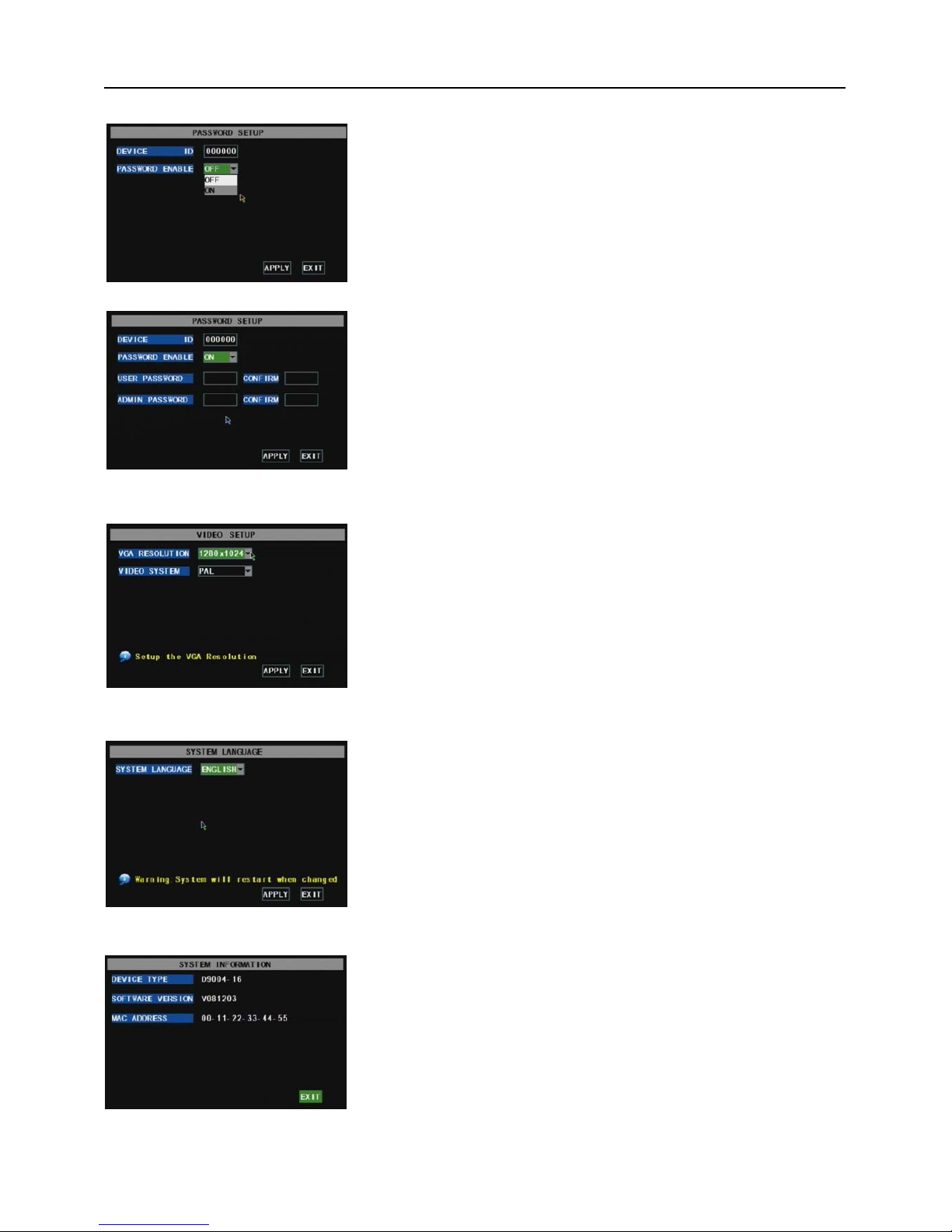
Enter into [System Language] menu to select the language
you want to use on the DVR (shown as Picture 5-45) and click
[APPLY] button. The selection will be available after system Auto
restarts.
Click [Main Menu SystemInfo] to enter into [System
Information] menu to view system info, including Device type, Software
(firmware) version and MAC address etc.
This option allows you set the device ID for the DVR and set
the system password if you want to use one. The new passwords
will be available after clicking [APPLY] button.
.
When you set Password Enabled to “ON” (shown as Picture
5-43), you can setup a user password and administrator password
respectively. The password supports up to 6 characters.
Click [Main MenuSystemVIDEO] to setup Video, here you can
set Camera system(PAL , NTSC)In the USA we use NTSC.
You can also set the resolution for the VGA video out port. Your
options are 600x480, 800x600, or 1024x768, or 1280x1024.
Picture 5-42
Picture 5-43
Picture 5-46
Picture 5-44
Picture 5-45
Page 28
User Manual
25
5.2.7.6 System Maintenance
5.3 Menu Lock
5.4 Video Search
Click pop-up menu video search to enter into [Video Search] menu you search files and playback
recordings. For more information on this operation refer to the previous section 5.24.
5.5 PTZ Control
Cruise Set
Open auto cruise function on PTZ setting menu if you want to setup cruise function (system default: on),
and set up cruise channel, cur point and total quantity and stop time etc.
Set: save the preset point. After setting channel and setting the position by adjusting PTZ direction key you
click [Set] button to setup the pre-set point. Please note you will click the [Save] button to finish the setting
successfully. If you want to combine Zoom, Iris, Focus and direction keys into the pre-set setting, please
return to previous menu (shown as Picture 5-56) to add additional settings, and then enter into Cruise Set
again and click [Set] and [Save] to make sure your setting is setup successfully.
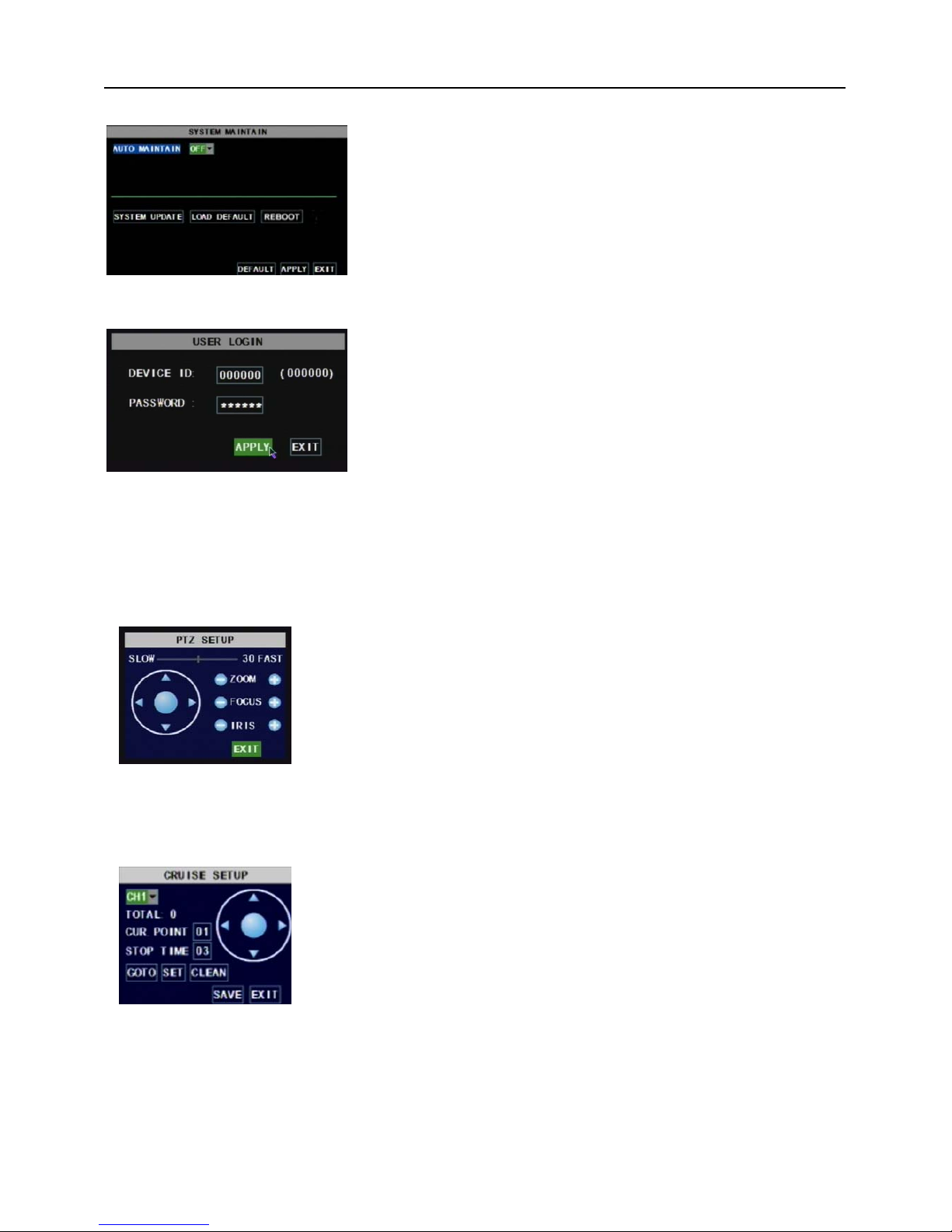
This option allows you reset the DVR to factory default settings,
update system software (firmware), and set system auto-maintenance.
Click [Main menuSystemMaintain] to enter into the [System
Maintain] menu (shown as Picture 5-47).
When opening auto-maintain function, you can setup system to restart
regularly.
As a system safety feature you can click [Menu Lock] menu to
lock menu when leaving the DVR. If you want to login to the DVR,
you would input device code and password (refer to the Menu
Locking interface- Picture 5-48).
Explanation: User only has the authority to search
recordings, but Administrator has full authority over Main
Menu operations
Picture 5-47
Picture 5-48
Picture 5-49
We introduced setting PTZ parameters previously in chapter 5.2.5.3.
Here we will discuss how to operate PTZ controls.
Click pop-up menu to show PTZ option and enter into PTZ control
interface (shown as Picture 5-49). You can now click Z+&Z- keys to zoom In
or out, click F+&F- keys to control camera focus and click I+&I- to adjust iris.
Channel select: select the channel with the PTZ camera
Total : set up presetting bit quantity
Cur Point: System has default starting (current) cruise point as 01. You
can use this option to set additional cruise points.
Stop time: sets the pause time at each stop.
GOTO:select this option to go to specific preset points
Page 29
User Manual
26
Clean: remove settings.
Note: this DVR model supports up to 100 pre-set points. But actual quantities may be restricted by the
PTZ camera you are using.
5.6 Record
When you want the system to start recording click [ Rec ] button to start manual recording.
5.7 Stop recording
If you want to stop manual recording click [Stop Record.] menu or [Stop] button
Chapter 6: Net-Viewer Program
6.1 Plug-ins download and installation
Open IE browser and input IP address and web port of DVR, such as http://172.18.6.202:80/ and confirm
to download and install webcam. If your computer is connected to internet, computer will auto download and
install the webcam.
Reminder: If the webcam is not downloaded successfully, please check if your browser’s safety level or
firewall setting is too advanced. Also refer to section 5.2.3 Network Setup to make sure network configuration
is correct, ports are forwarded correctly, and ActiveX is enabled.
6.2 Log-in to NetViewer
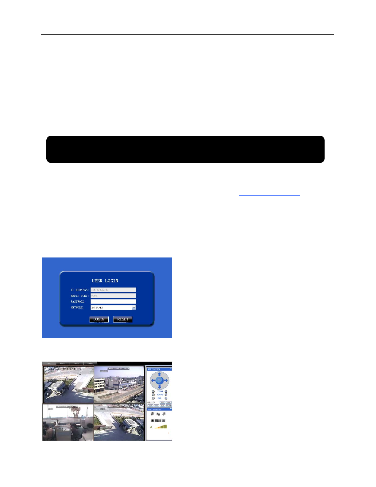
After webcam installs plug-ins, please select log-in
language (Chinese or English) and enter password and
click [Log-in] button, and now you can view DVR
remotely through NetViewer.
Please note default password is empty. System
allows Administrator to set new password as per
instructions in section 5.2.6.2 - [Password set] menu.
Note: If you want to delete old IE webcam at DVR
system update, run the command characters:
“regsvr32/u dvrocx.ocx”
After successful Log-in to Net-viewer, system will
enter into live display interface and connect to
audio/video feed automatically (shown as Picture 6-2).
Picture 6-1
Picture 6-2
Page 30
User Manual
27
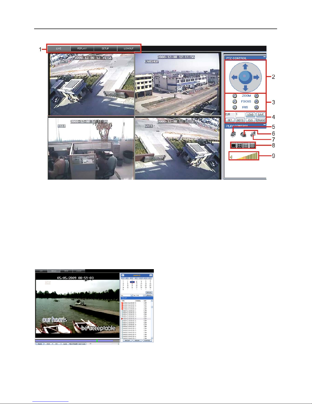
6.3 Main Interface of Net-viewer
Picture 6.3
Log in Net-viewer and show the interface as follows
6.3.1 Menu column (Section 1 on Picture 6-3)
6.3.2 PTZ Control (Numbers 2, 3, 4 on Picture 6-3)
6.3.3 Live Play Control (Numbers 6 through 10 on Picture 6-3)
6.3.1 Menu column
Menu column include [Live] menu, [Replay] menu and [Setup] menu and [Logout] menu.
6.3.1.1 Live
After Logging-in to system, system will enter into Live display (shown as Picture 6-3).
6.3.1.2 Replay
Play button: [Play]/[Pause]
Stop button: stop playing recording.
F.F. button: fast forward playback recording
This option allows you to playback recordings
remotely.
First select the day, channel and type and
proceed searching and refreshing; second select
any event from search result list to playback.
Please note you can control playing speed by
sliding the playing-control bar on the bottom of
the interface (shown as Picture 6-4).
(Section 1 on Picture 6-3)
Picture 6-4
Page 31
User Manual
28
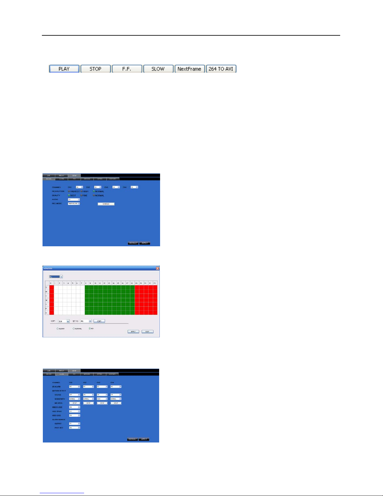
Slow button: slow playback recording.
Next Frame: play frame by frame.
264 TO AVI button: convert file from H.264 format to AVI format
The native format of the backup files is H.264, you can convert H.264 format into more familiar AVI format
by clicking the key of 264 to AVI.
6.3.1.3. Setup
Click [Setup] menu to enter into its sub menu, including [Recording Mode] menu, [Alarm Mode] menu,
[PTZ Control] Menu, [Network Setting] menu, [System Setting] menu and [Host Info] menu.
Explanation: Only when DVR is on the status of live display, you could modify and save its parameters
remotely at this moment, the settings are available. The modification method to DVR via Net-viewer is the
same as local adjustment of DVR.
① Record
② Alarm
Click [Alarm] menu to enter into its sub menu (shown as
Picture 6-7).
You can set I/O alarm for every channel, motion detection
alarm, motion recording, motion trace, motion sensitivity, video
loss alarm, HDD not enough space alarm, HDD not found
alarm and alarm output time etc.
For details on setup method please refer to section
5.2.5.2.
Picture 6-5
Enter into sub menu – [Recording Mode] menu, you can
select on/off for every channel, and adjust recording
parameters (resolution, quality, audio, REC mode and
Schedule) remotely via Net-viewer.
Picture 6-7
Picture 6-6
Click the [Schedule] menu to enter into its sub menu
(shown as Picture 6-6).
Remote setup methods are the same as local DVR
setup. Please refer to Section 5.2.2 Record Setup
Page 32
User Manual
29
③ PTZ Control
④ Network
⑤ Setting
⑥ Host Info
-
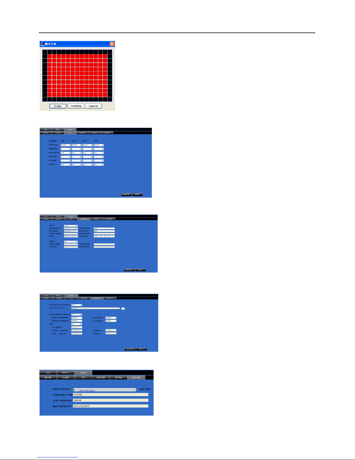
System allows you setup motion detection settings for each channel
of DVR remotely (shown as Picture 6-8)
Picture 6-9
Click [PTZ control] to setup PTZ cameras. Remote
setup methods are the same as local DVR setup.
Please refer to Section 5.2.5.3 (shown as Picture
6-9).
Click [Network] to enter into [Network]
menu. Remote setup methods are the same as
local DVR setup.
Please refer to Section 5.2.3. – Network
Set.
Picture 6-10
Picture 6-11
Click [setting] menu to enter into the menu interface
(shown as Picture 6-11);
Click […] button to preview net-viewer recording
saving path and screen capture saving path.
The menu also allows you to set a lower bandwidth for
Internet video transmission, set user password, turn
daylight saving time on/off, etc.
Click [Host Info.] to enter into the sub menu (shown as
Picture 6-12). Here you can check Usage rate of HDD,
available recording time, software version and MAC address.
Picture 6-12
Page 33

User Manual
30
6.3.1.4 Log out
Log out of the system.
6.3.2 PTZ Control
Note: below-mentioned series no will be consistent with the remark no shown as Picture 6-2.
○2.PTZ direction control: Control PTZ moving direction
○3.Zoom, Focus and Iris Control: control direction, zoom, focus and iris of PTZ.
○4.Presetting bit Control
CUR:display current presetting bit or input a presetting bit you want to fix at according edit box。
Load:Load one presetting bit setting you have saved last time.
Save: Save presetting bit.
Set: set presetting bit parameter (Details setting method please refer to section 5.5- cruise set.
GOTO: on the preview mode, please input one presetting bit no and click [GOTO] button, you could
fix the presetting bit quickly.
Clean: clean presetting bit setting
Cruise: control cruise status (including on and off).
6.3.3 Live Play Control
⑤On / Off Live display [ ]:When Live display status is “On”, Clicking the button closes Live display. When
“Off” clicking the button opens the Live display.
⑥.Capture [
]:Capture Screen image and save to PC as *bmp image.
⑦.Recording [
]:Operate DVR recording remotely
⑧Channel display [
]:The icons stand for Single Channel display, Quad Channel display, 3x3
Channel display and 4x4 Channel display respectively.
⑨.Volume control [
] Click or slide the control bar to adjust sound volume.
(Numbers 2, 3, 4 on Picture 6-3)
(Numbers 6 through 10 on Picture 6-3)
Page 34
User Manual
31
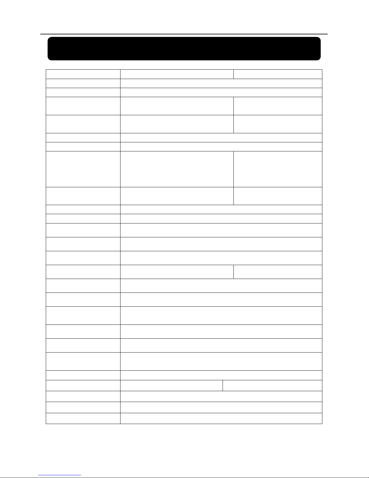
Chapter 7: Specifications
Model
4CH 8CH
Video System NTSC / PAL(Optional)
Compression Format
Video:H.264 / Audio:8kHz*16bit ADPCM
Video Output 4-CH BNC Input/ 2-CH BNC Output / 1-VGA output
8-CH BNC input/2-CH BNC output / 1-
VGA output
Audio I/O 4-CH RCA audio Input / 2-CH RCA audio Output
1-CH RCA audio input/ 1-CH RCA audio
output
Display Resolution
D1:704×576(PAL) 704×480 (NTSC)
Frame rate
Single CH PAL:25 fps ,NTSC:30 fps
Recording Resolution
PAL: CIF(352*288), HD1(704*288) D1 (704*576)
NTSC:CIF(352*240),HD1(704*240) D1 (704*480)
PAL :CIF(352×288)
NTSC:CIF(352×240)
Recording Frame Rate (shared)
PAL:25 fps@D1, 50 fps@HD1, 100 fps@CIF
NTSC:30 fps@D1, 60 fps@HD1,120 fps@CIF)
PAL:200 fps@CIF
NTSC:240 fps@CIF
HDD
1 SATA HDD, up to 1024GB;USB removable HDD
Video Mode
Always / schedule / manual /motion detection / sensor triggered
Record Pack Time
15/30/45/60min
Video backup
USB flash disk / removable HDD,USB Burner, Network backup to AVI File Format
Playback Mode
PLAY /SLOW /FWD/Frame by Frame
Alarm I/O 4-CH alarm inputs, 1-CH alarm output 8-CH alarm inputs,1-CH alarm output
Alarm Type Motion/ sensor triggered/Video loss/HDD Space/HDD Loss
PTZ Control Built-in RS-485 port, supports PELCO-P & PELCO-D
USB 2.0 Port
Supports USB mouse,removable HDD,USB flash drive to ba ckup to A VI fi le and upgrade
system
Ethernet One RJ-45 10M/100M self-adaptable Ethernet interface
Network Protocol Supports TCP/IP, DHCP, UDP, DDNS, PPPOE network Protocol
Network Function
Support preview live display remotely via mobile phone and real time monitoring via IE-based
browser and/or network, and support parameter setting of DVR remotely
.
Power consumption
10~15W (exclude HDD)
Power Adapter DC 12V / 3A DC 12V / 3A
Working Temperature
50°F to 104°F (10℃ to 40℃)
Working humidity
10%~90%
Dimension (W x D x H)
11.75 x 9 x 2 in (300 × 220 × 47 mm)
List 7-1
Page 35
User Manual
32
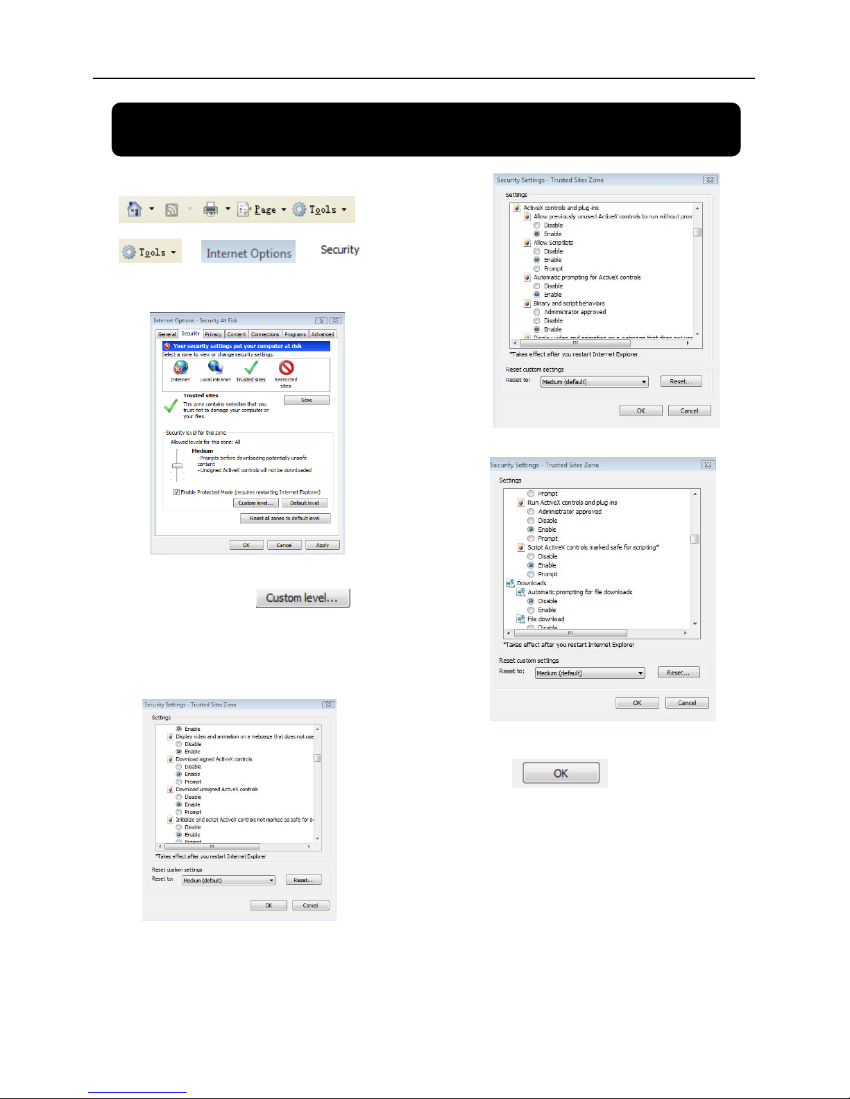
Chapter 8: Windows Vista User
1、Open IE browse firstly, then enter into Tool bar-
and select
to
appear the below picture:
2、Second, select icon
and tick the settings of “ActiveX
controls and plug-ins”to Enable, details
as follows:
3.
4.
Lastly after tick all the “Enable”, please
click to exit. At this
moment, you could input IP address to
run your programme.
Page 36
User Manual
33
Open IE browser and input IP address and web port of DVR…computer will auto downloadand install the
widget.
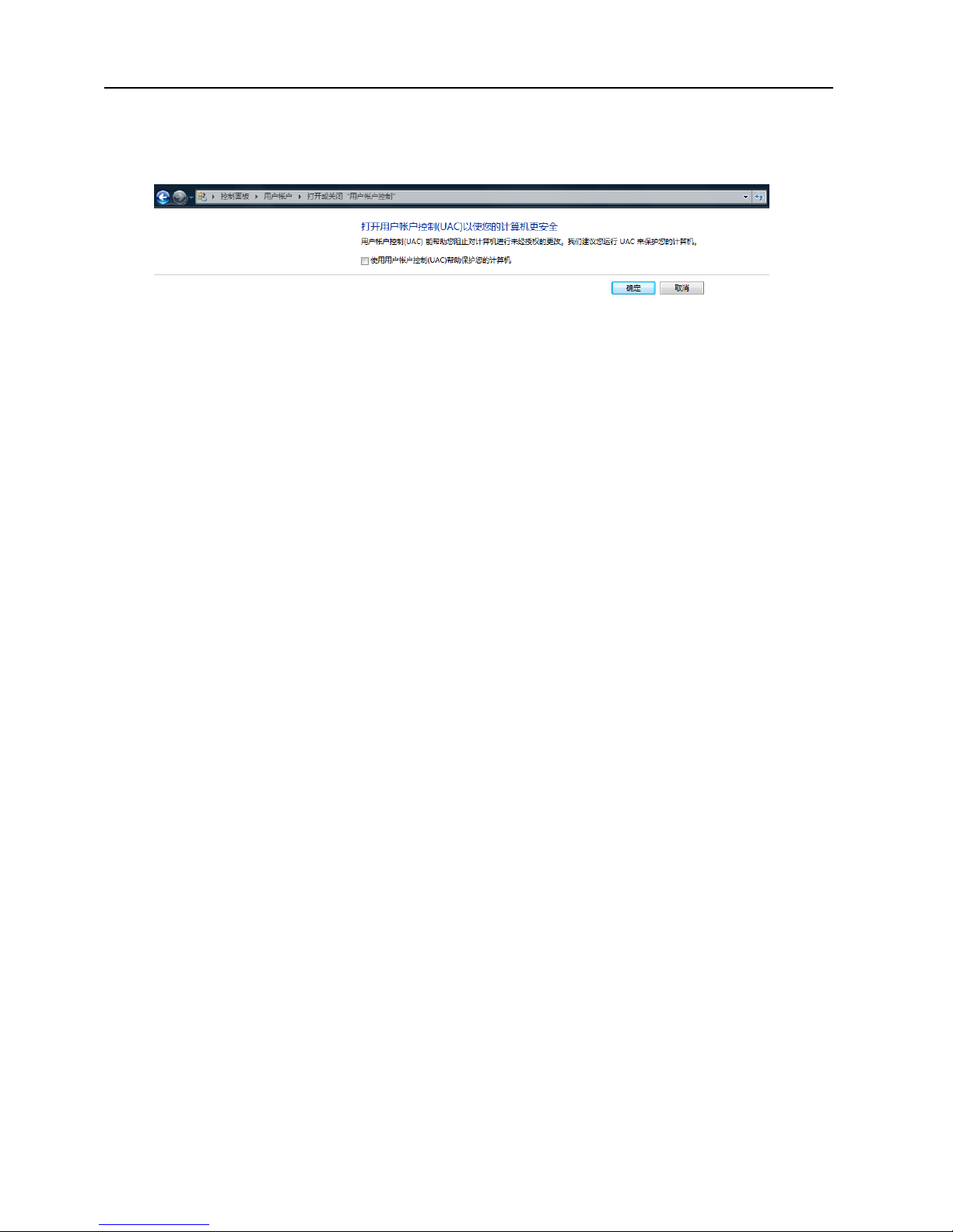
We suggest Visita user set user access authority in order to make your PC safer. Setting processing as follows:
Click [StartSetControl panelUser account] to set user access authority shown as below picture.
Remind: If the widgets are not downloaded successfully, please check if your browser’s safety level or
firewall setting is too advanced.
Open IE browser to enter into [tool Internet OptionInternet user-defined levelenable widgets.
Downloading and auto running install widgets need one minute, please wait…patiently.
Page 37

User Manual
34
Chapter 9: Appendix
9.1 Operation Function Table
Type Title Description
Page
Time setting Setting system date, time and format and day-light saving time setting 21
Language Select Setting system language 22
CH Setting
Setting CH title and position; adjusting image color parameter value; setting CH display to
ON / Off and time display/recording time overlaying to On/Off.
11
Rec. Setting Setting image quality, resolution, volume, recording mode an pack time 12
Rec. Search Time based search, channel based search and rec. mode based search. 14
Rec. Playback Specified time playback, scheduled playback, file list playback 14
Playback mode Play, play frame by frame, multi-speed forward and multi-speed rewind 14
File backup
U flash disk and removable HDD backup, DVD recorder backup and network
download backup
15
HDD Manage Check HDD status, usage space, setting HDD auto-overwrite 16
Principle
Setting
VID/AUD Setting Adjust VGA resolution, select system and volume control 22
User password Setting or modifying user password 21
Alarm setting
Setting HDD lost, HDD space, video loss, I/O status, alarm management and Email alarm
26
Motion detection
Setting on/off status of MD; select sensitivity and setting motion detection
area.
20
PTZ control Selecting CH and setting PTZ protocol, baud rate and PTZ address for the CH 27
MP Monitor Setting user name, password and server port.
Advanced
Setting
System
Maintenance
Setting system auto maintenance, maintenance time regularly, system upgrade,
ex-factory default value recovery and manual restart system
22
Network
Setting
Network and Port
setting
Selecting network mode and setting net-viewer port, web port, DNS and
DDNS parameters.
27
Live display Real time video input remotely 25
Remote recording Setting recording mode and status of DVR remotely 28
Remote playback Check local recording history via network 25
PTZ control Remotely control PTZ camera, position, focus, zoom and iris etc. 28
parameter set of
DVR remotely
Setting local CH display, recording, alarm, PTZ control parameter value via
network
26
Network
Function
Network download
Backup recording file via network 25
System info Check device model, software version and MAC address 28
Auxiliary
function
()
In addition to illustrating picture, Parenthesis generally indicate optional
parameter value of previous menu.
Confirm The button allows you save the modification of parameter value.
Recover default The button allows you recover default value of current menu or system
Exit The button allows you exit the current menu.
Menu
button
Next
On multi-channel mode, the button allows you check or modify other channel’s parameter;
on [File list] mode, the button allows you display next page.
List 9-1
Page 38
User Manual
35
9.2 Recording Alarm setting
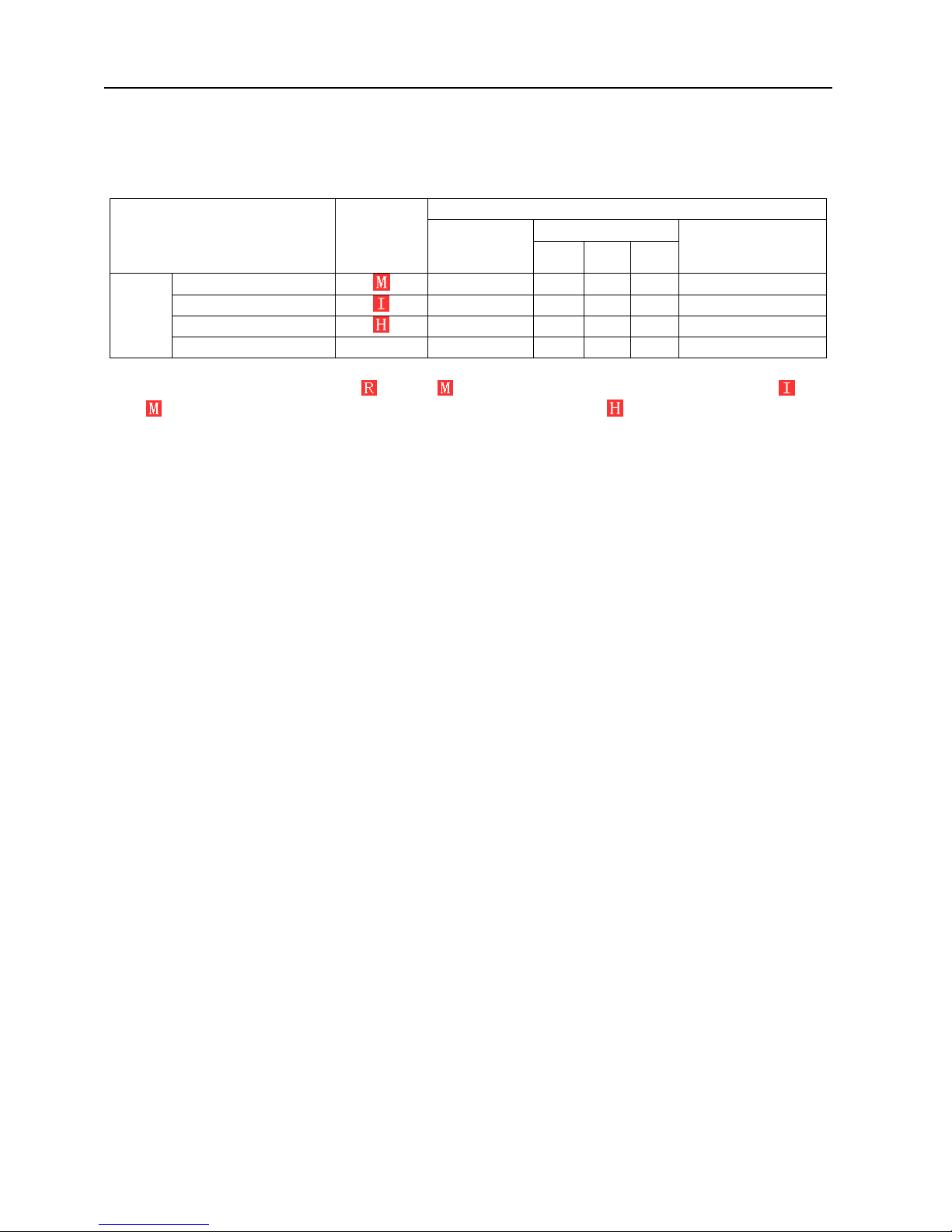
Please refer the below matrix: “⊥” stand for “only alarm but no recording”; “AMR” stand for “alarm
recording”; “NLR” stand for “normal recording”; and “NOR” stand for “ no recording”. Once alarm is triggered,
alarm icon will occur, and when many alarms are triggered, alarm remarks will occur on the screen.
Recording Mode
Timing recording
Recording alarm setting Alarm icon
Recording after
power on
AMR NLR NOR
Manuel Recording
MD alarm AMR AMR NLR ⊥ NLR
I/O triggered alarm AMR AMR NLR ⊥ NLR
HDD loss, HDD space full ⊥ ⊥ ⊥ ⊥ ⊥
Alarm
mode
Video Loss Video Loss ⊥ ⊥ ⊥ ⊥ ⊥
List 9-2
When DVR is in recording mode, [
] icon or [ ] icon will appear on the screen. But when there are [ ] icon
and [
] icons on the screen it indicates a motion alarm was triggered. When [ ] icon appears on the screen, that
mean a hard drive alarm has occurred.
9.3 Troubleshooting
1. Q: What can I do if the system does not detect the HDD?
A: Check the data and power cables and make sure they are securely connected.
2. Q: We have changed the password but do not remember the new password, how can we access the system?
A: If you forget system password, enter 0800808 into the password field to reset the password
3. Q: We are not getting any video signal on the DVR, what is wrong?
A: Check to make sure the cables are securely connected to the BNC ports on the DVR. You can also try another
cable to make sure there is not a problem with the cable. Make sure you have selected the correct video format for
your country (NTSC or PAL), is the USA we use NTSC.
4. Q: Can the DVR have problems if it gets too hot, how can I prevent this?
A: The DVR has a fan to help it dissipate h eat while it is work ing. Please pl ace the DVR in a pla ce where there
is good air circulation and away from high temperatures to increase stability and life of the DVR.
5. Q: My remote control does not work when the DVR is in Live mode but the front panel buttons are working,
what is wrong?
A: Make sure nothing is blocking the LED on the remote, or the receiver on the DVR, if both are ok, check the
batteries.
6. Q: Can I use the hard drive from my PC in the DVR?
A: You can if the hard drive is the same type and the size is supported by the DVR. If you install it in the DVR it
will be formatted for use in the DVR and the PC will not be able to read it.
7. Q: Do I have to stop recording to playback files on the DVR?
A: No you do not have to stop recording, the DVR will support both functions at the same time.
8. Q: Can I erase files from the hard drive of the DVR?
A: You can not erase individual files, you would need to format the hard drive which will erase all of the files
9.Q: Why can’t I log-in to the Net-viewer program?
A: Please verify that the Net mode is correct, The cable to the RJ-45 port is well connected to the DVR and the
router, and that you are using the correct password.
10. Q: We have attached a PTZ camera but can not control it, what is wrong?
A: Verify that the Protocol, baud rate, address, and other settings on the PTZ camera match the settings you have
put into the DVR. Make sure the data cables are attached firmly to the RS485 port on the DVR.
11. Q: Why does the Buzzer keep sounding?
A: Please check to see if motion detection is on and the system has detected motion, make sure the hard drive is
being detected and has sufficient space available, and that none of your cameras have lost video. You can turn off
the buzzer in the Alarm setup option.
Page 39

User Manual
36
9.4 Email server check list(The below info only for your ref.)
(Web site)
Email address
Sender server(25) Receiver server(110)
@163.com smtp.163.com pop3.163.com
@vip.163.com
smtp.vip.163.co
m
pop
.vip.163.co
m
@188.com
smtp.188.co
m
pop
.188.com
@126.com smtp.126.com pop3.126.com
@netease.com smtp.netease.com pop.netease.com
www.163.com
@yeah.net smtp.yeah.net pop.netease.com
www.163.net smtp.163vip.net popx.163vip.net
www.sina.com @sina.com.cn smtp.sina.com.cn pop3.sina.com.cn
@yahoo.com.cn smtp.mail.yahoo.com.cn pop.mail.yahoo.com.cn
www.yahoo.com
@yahoo.com smtp.mail.yahoo.com pop.mail.yahoo.com
www.google.com @gmail.com smtp.gmail.com(465/587) pop.gmail.com(995)
www.china.com @china.com smtp.china.com pop.china.com
www.sohu.com @sohu.com smtp.sohu.com pop.sohu.com
www.163.net smtp.163.net pop.163.net
www.163vip.net
smtp.163vip.net pop.163vip.net
www.tom.com @tom.com
smtp.tom.com pop.tom.com
www.263.net @263.net smtp.263.net
pop
3.263.net
x263.net smtp.x263.net
pop
.x263.net
263.net.cn smtp.263.net.cn
pop
.263.net.cn
www.qq.com @qq.com smtp.qq.com pop.qq.com
www.139.co
m
@139.com
smtp.139.co
m
pop
.139.co
m
www.21cn.com
smtp.21cn.co
m
pop
.21cn.co
m
21cn VIP mail
vip.21cn.co
m
vi
p
.21cn.co
m
etang.com
smtp.etang.com pop.etang.com
elong.com:
smtp.elong.com pop3.elong.com
List 9-3
9.5 Usage Maintenance
1. Please make sure DVR keep away from heating source.
2. Clean the internal dust regularly, keep DVR aeration well and be easy to heat dissipate.
3. Please not plug in RS-232 and RS-485 when power is on to avoid any damage to the port.
4. Please check the HDD cable and data cable to avoid the cable aging.
5. Please avoid other electronics device interfere video/audio signal of DVR a.s.a.p., or static electricity and
induced voltage damage to DVR.
6. Suggest user replace BNC cable regularly to keep signal input stable.
Page 40
User Manual
37
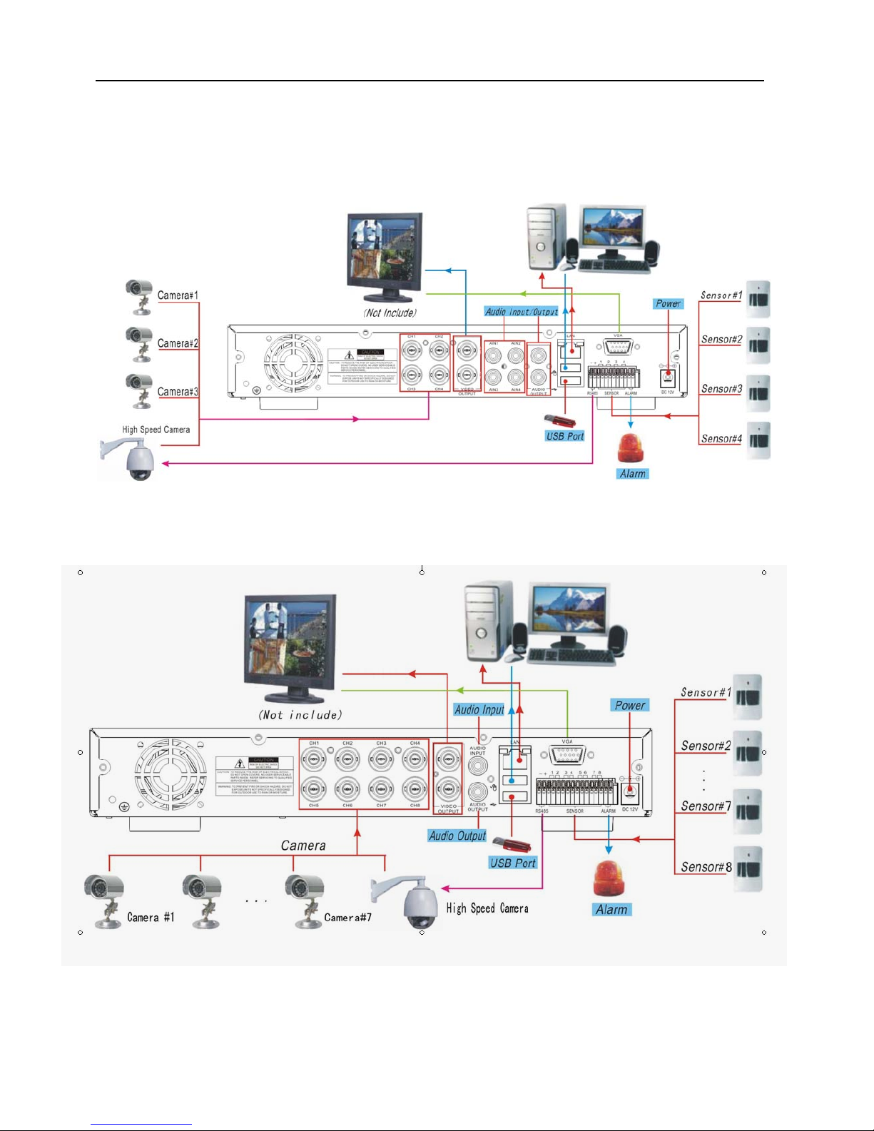
9.6 System connection Configuration
4-CH.
8-CH
Page 41

User Manual
The material in this document is the intellectual property of our
department .
No part of this manual may be reproduced, copied, translated,
transmitted, or published in any form or by any means without our
department prior written permission.
Our products are under continual improvement and we rese rve the right to
make changes without notice. But n o guarantee is gi ven as to the correctness
of its contents.
We do not undertake any res ponsibility for the harms cause by using our
product.
The model of the product s in the user's manual on ly for recog nitio n, but
these names also perhaps are belong to other company's registered
trademar k or the copy right.
The product picture may differ from the actual product, only for your
reference. The accessories will probably be different according to the
differ ent sell ing ar eas. For details of accessori es, please refer to your local
distribut or.
ٛ
ٛ
ٛ
ٛ
ٛ
Copyright reserved
 Loading...