

CCTV CCM-1481, EXM-1481 User Manual

CCM / EXM-1481
1
USER MANUAL
MECHANICAL IR FILTER OLPF
DAY/NIGHT
DIGITAL COLOR CCD CAMERA
1/3” HI. RESOLUTION
24VAC + 12VDC
1. General description
This 1/3” Day/Night color CCD camera, with high resolution (470/410 k) picture
elements, is equipped with a mechanical IR filter and advanced Digital Signal
processor to provide an unprecedented optimal image with vivid and stable true color
picture up to 500TVL (color mode) in Day time and 520TVL (b&w mode) without focus
shift when under IR light at night time.
2. Features
a. Day/Nigth mode: The built in mechanical IR filter design allows the camera to work
at true color mode under day light condition and Mono mode under no visible light
condition with IR projector.
b. Resolution: perform 500 TV line at day time (color) and 520 TV line at b&w
c. Low light sensitivity: By employing high sensitivity image sensor and low noise
circuit design the camera is capable of a 0.5 lux (color mode) and 0.1 lux(b&w
mode) low light sensitivity produces and a 48 dB signal-to-noise ratio.
d. White Balance: The wide range Auto Wide Balance (AWB) and Auto Tracing
white balance (ATW) allowing the camera to adjust color tone automatically
according to the color temperature of the light source illuminating the subject.
e. Back Light Compensation: Smart digital control Auto BLC, enable the camera to
be used against any unusual back light conditions.
f. Auto Exposure System: Advanced Auto Exposure System for both CCD iris and
auto iris lenses controlling the amount of light to ensure the optimal picture
quality.
g. User selectable Internal or external Line-lock sync. mode.
CCM / EXM-1481
2
DC VIDEO
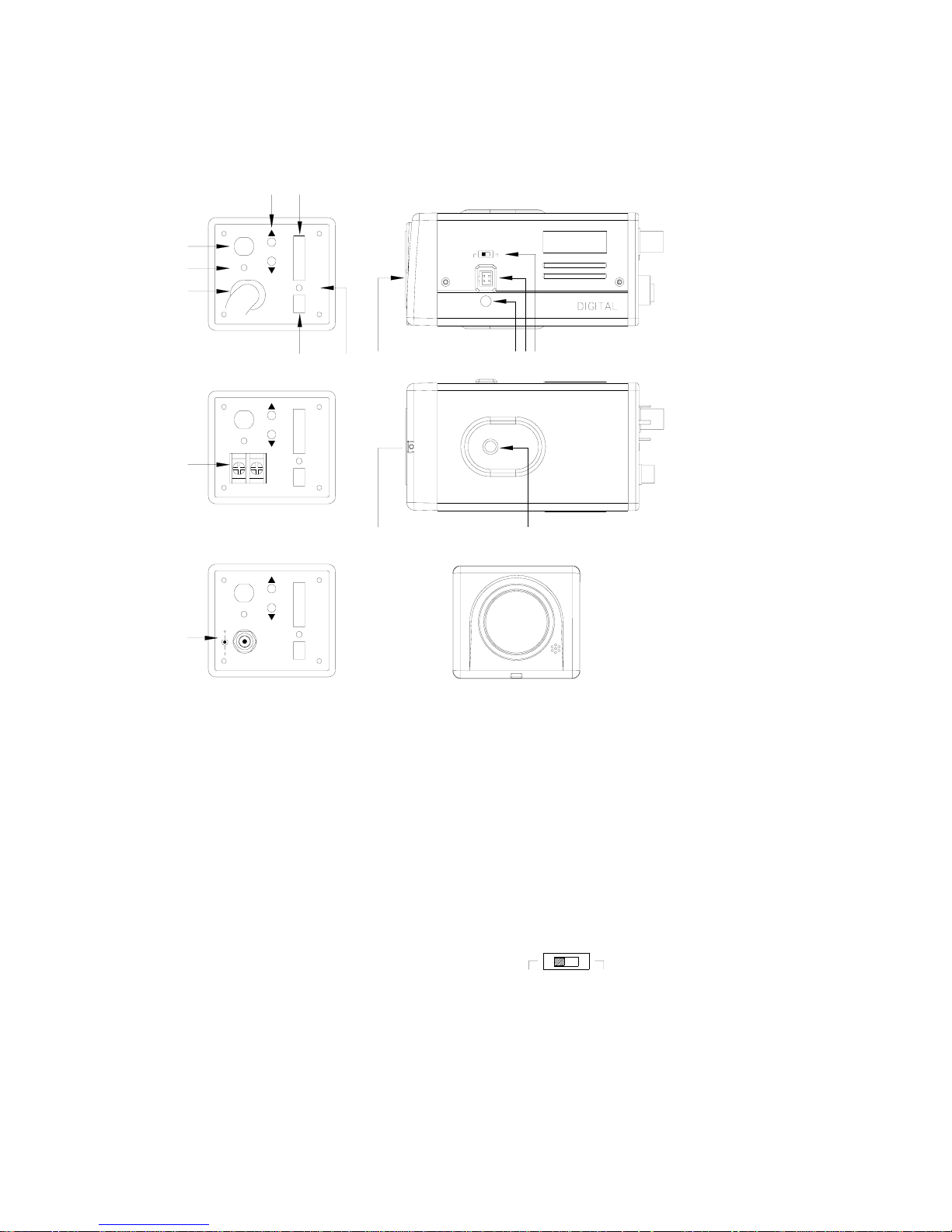
3. Name of parts and functions
a. C(CS)mount adapter
If a CS mount lens is to be used, remove the C mount ring.
b. DC lever Adjuster(VR)
For DC drive auto iris lens driving level adjustment; in order to obtain correct
exposure light.
c. Auto iris lens connector(MINI JACK) See section III-1 auto-iris connector.
d. Video/DC auto-iris lens selector
DC—For DC Drive lens
Video—For Video drive lens
e. Flange focal lock screw
f. Camera mounting screw hole
Standard photographic pan-head screw size(1/4”-20)
V-phase
M
DC 12V
VIDEO OUT
PL
LONG
SHORT
DELAY
TIME
DELAY
T5
T1
T3
T6
T4
DELAY
T2
AE
FLOFF
AES
BLC
ATW
AGC
NC
AI
AWB
BLCOFF
SUPAGC
NC
FLON
ME
E
H
V-phase
V-phase
L
DC 12V
AC 24V
PL
AC85V~265V
VIDEO OUT
K
J
I
VIDEO OUT
PL
T5
T6
O
MEAES
TIME
DELAY
T3
T1
T5
DELAY
LONG
AE
FLOFF
INT
AGC
ATW
BLC
T4
T6
T2
AWB
DELAY
SHORT
L.L.
FLON
SUPAGC
BLCOFF
AI
N A
TIME
DELAY
BLC
DELAY
LONG
T3
T1
INT
ATW
AGC
AE
FLOFF
AES
BLCOFF
DELAY
T4
T2
SHORT
AWB
SUPAGC
L.L.
FLON
ME
AI
G
F
DC LEVEL
DBC
DC VIDEO

CCM / EXM-1481
3
V-phase
1
2
3
4
DC 12V
g. Dip Switchs
h. Phase Adj.
Line-lock Phase Adj.(Line-lock model)
i. Video output terminal(BNC)
This connector is used to provide video signal output.
j. Power LED
k. AC85V~265V Power Cord
l. DC 12V or AC24V & DC 12V terminal block
m. DC 12V power input terminal
n. Delay time selectable table
o. LONG delay and SHORT delay time LED
3.1. Auto Iris Lens Connector
● Use the accompanying auto iris lens connector plug.
For auto iris lens with built-in EE amp.(VIDEO Type)
Set the Iris selector switch to “Video” position.
Connector cable leads definition:
1.Red----power 2.NC
3.White----video 4.Black----shielded
For auto iris lens without EE amp.(DC Type)
The connector drawing shows external view from camera.
Set the lens iris selector switch to “DC” position.
Connector cable lead definition:
1.Damping coil(-) 2.Dampling coil(+)
3.Driving coil(+) 4.Driving coil(-)
Connect the leads as shown above; please refer to the instructions of the lens for
more detail.
3.2. Power Terminal
3.2.1 DC 12V model
Connect the power supply to the power-input terminal as shown above.
1. Power range for the camera is 12VDC±10%.
2. Connector’s center pole is positive 12V DC and the outside shell is common ground.
AGC
INT
ATW
FLOFF
BLC
AES
AE
SUPAGC
L.L.
AWB
BLCOFF
FLON
AI
ME
AGC MODE
SYNC MODE
LONG DELAY / SHORT DELAY OPTION
WB MODE
AE SETTING
DELAY
SHORT
DELAY
LONG
 Loading...