

CC Systems CC Pilot XS Basic, CC Pilot XS Extended, CC Pilot XS All-Integrated User Manual And Reference Handbook
Page 1
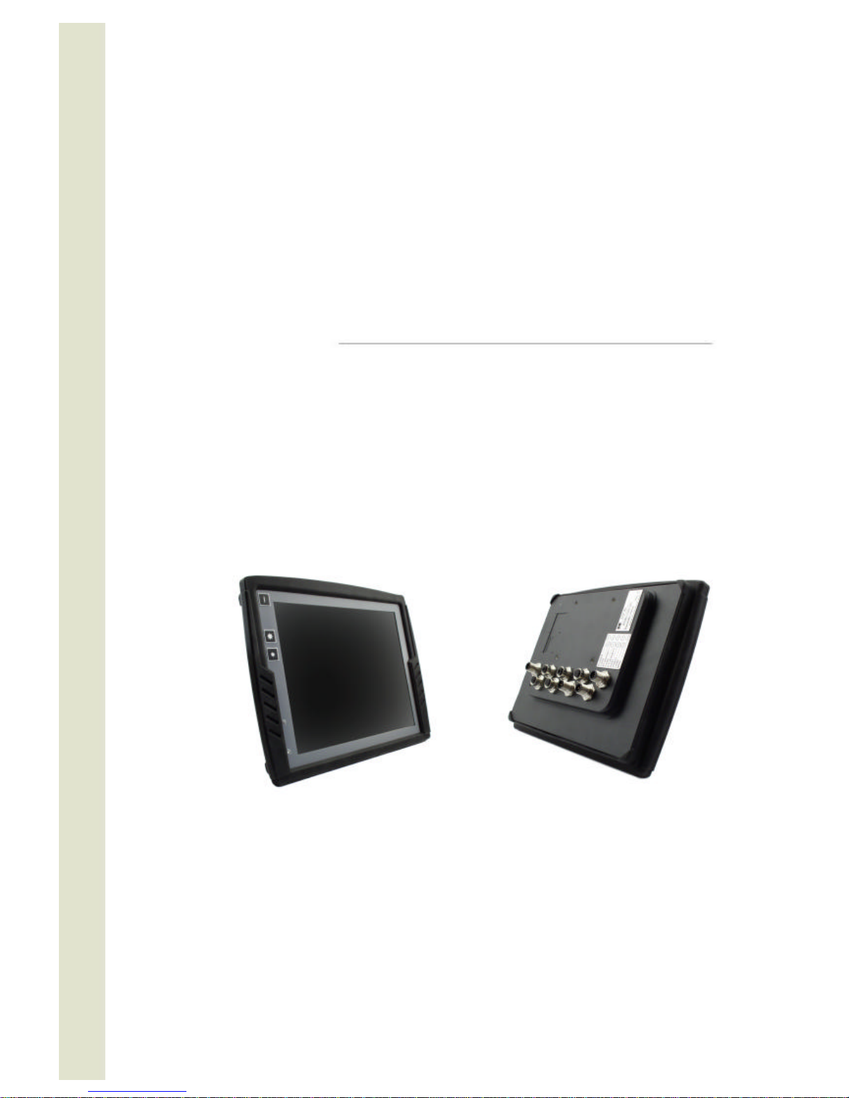
CC Pilot XS, rev. 1.3 080812
CC Pilot™ XS
User Manual and Reference Handbook
CC Pilot™ XS Basic
CC Pilot™ XS Extended
CC Pilot™ XS All-Integrated
Page 2

User Manual and Reference Handbook for the CC Pilot ™ XS
2
Table of Contents
Introduction.................................................................................................................................................................................4
Identification..........................................................................................................................................................................4
Care........................................................................................................................................................................................4
Environment and Environmental Tolerance .....................................................................................................................5
Cleaning.................................................................................................................................................................................5
Overview.....................................................................................................................................................................................6
CC Pilot™ XS Front Face...................................................................................................................................................7
CC Pilot™ XS Rear Side .....................................................................................................................................................7
Set-up and configuration..........................................................................................................................................................8
Preliminary configuration .....................................................................................................................................................8
Basic operations ........................................................................................................................................................................9
Function of the Display’s Push-buttons ............................................................................................................................9
Starting Up .............................................................................................................................................................................9
Status Indicating Function .................................................................................................................................................10
Shutting-Down ....................................................................................................................................................................10
Touch screen......................................................................................................................................................................10
Reset of the unit..................................................................................................................................................................11
Module description..................................................................................................................................................................12
Storage memory.................................................................................................................................................................12
CAN ......................................................................................................................................................................................12
Ethernet................................................................................................................................................................................12
USB......................................................................................................................................................................................13
COM.....................................................................................................................................................................................13
Digital Inputs........................................................................................................................................................................13
Audio....................................................................................................................................................................................13
Video....................................................................................................................................................................................13
GPS......................................................................................................................................................................................13
GPRS/GSM.........................................................................................................................................................................14
Bluetooth..............................................................................................................................................................................14
Connectors................................................................................................................................................................................15
Connectors ..........................................................................................................................................................................15
Installation.................................................................................................................................................................................21
Placing and installing of the unit and peripherals..........................................................................................................21
Software ....................................................................................................................................................................................27
Operating System...............................................................................................................................................................27
Getting Started with Windows CE ....................................................................................................................................27
XS Settings..........................................................................................................................................................................32
CC Video ..............................................................................................................................................................................36
Microsoft ActiveSync..........................................................................................................................................................38
Page 3

User Manual and Reference Handbook for the CC Pilot ™ XS
3
Program installation...........................................................................................................................................................40
Connect to the GPS receiver............................................................................................................................................40
Creating a dial-up connection with the GSM/GPRS modem.......................................................................................40
Using the FTP server.........................................................................................................................................................42
Using Telnet server............................................................................................................................................................42
Specifications ...........................................................................................................................................................................43
Computer Core...................................................................................................................................................................43
Interfaces.............................................................................................................................................................................43
Power Supply......................................................................................................................................................................44
Display..................................................................................................................................................................................44
GPS......................................................................................................................................................................................44
GSM/GPRS.........................................................................................................................................................................45
Bluetooth..............................................................................................................................................................................45
Environmental Tolerance..................................................................................................................................................46
Weight and Dimensions ....................................................................................................................................................47
Technical Support....................................................................................................................................................................51
Glossary ....................................................................................................................................................................................52
References................................................................................................................................................................................54
Trade Mark, etc........................................................................................................................................................................54
Index ..........................................................................................................................................................................................55
Page 4
User Manual and Reference Handbook for the CC Pilot ™ XS
4
CC Pilot™ XS
Introduction
In this user manual and reference handbook you, as a user, a reseller or system
integrator, will find important information about the CC Pilot™ XS. The handbook will
guide you and broaden your knowledge about this onboard computer’s technical
possibilities and advantages. Described herein are the CC Pilot™ XS Basic, CC Pilot™
XS Extended and CC Pilot™ XS All-Integrated versions.
This material is copyright protected © 2005 CC Systems AB. All rights reserved.
Identification
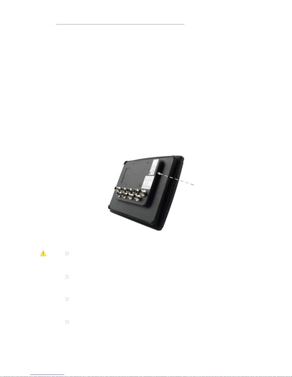
There is a brand label on the back of the CC Pilot™ XS. On the brand label there are
numbers which identify your unique computer. During service and other contact with
the supplier it is important to be able to provide these numbers.
Care
During welding or other service , on the vehicle or machine where the CC
Pilot™ XS is installed, which can damage your CC Pilot™ XS, all cables shall
be disco nnected from you computer before such work begins.
The CC Pilot™ XS shall only be mounted and serviced by authorised
personnel. If the unit is opened by unauthorised personnel, the normal
guarantee will cease to be valid.
Scratches, or in the worst case damages, to the display occur easily if it comes
in co ntact with a sharp edge or hard material. In order to increase the longevity
of the screen, this is naturally something which should be avoided.
The unit can be damaged if it becomes too hot. Therefore, do not cover the unit
by laying things on it, like for example, hanging a jacket or other clothes on it.
For more information, see the chapter entitled Installation.
Brand Label
Page 5

User Manual and Reference Handbook for the CC Pilot ™ XS
5
Consider traffic safety when the CC Pilot™ XS is installed and whenever it is
used. CC Systems AB does not recommend that CC Pilot™ XS or its
accessories be used actively by the driver when a risk of injury to people, or
damage to property, is present.
Be advise d that CC Pilot™ XS draws power from the vehicle battery. This can
result in the inability of the vehicle to start if the onboard computer has been on
for a period of time without the vehicle motor running.
Environment and Environmental Tolerance
The CC Pilot™ XS has been designed to cope with tough environmental demands.
Strict tests have been conducted on the unit in order to ensure that it fulfils the
expectations of a rugged unit. Much work has been performed to choose and design
internal components so that they, in the best possible way and under all circumstances,
provide you with a dependable and user-friendly working instrument. In the section
Specifications, a list of standards can be found according to which the CC Pilot™ XS
has been tested and approved.
The CC Pilot™ XS shall preferably be placed under a roof in order to prevent exposure
to direct water contact. It is also important that it is mounted securely on a stand or the
like to inhibit the unit from moving and thereby becoming damaged, damaging the
vehicle and/or people during, for example, a traffic accident.
Cleaning
To ensure proper and reliable functionality over time, the unit shall be wiped cleaned of
dirt and dust. Use a suitable light damp rag to clean the unit.
Never use alkaline, alcoholic or other chemicals for cleaning which can damage the
unit.
Page 6

User Manual and Reference Handbook for the CC Pilot ™ XS
6
CC Pilot™ XS
Overview
The CC Pilot™ XS is a compact, robust and versatile onboard computer for Wi ndows
CE 5.0. It is equipped with, among other things, a pressure-sensitive touch screen as
well as a large number of connection alternatives such as CAN, COM, Ethernet and
USB. The CC Pilot™ XS comes in three different versions:
• Basic – the essential functions for a on-board computer
• Extended – Adds Video and Audio functionality
• All-I ntegrated – Adds GPS and GSM/GPRS abilities
The processor in the CC Pilot™ XS is an Intel XScale® processor with a clock
frequency of 533 MHz. The characteristics for this processor type are its low current
draw and heat generation in proportion to its performance. Together with a non-rotating
hard disc, the CC Pilot™ XS is completely without fans or other moving parts. With this
solution the CC Pilot™ XS becomes nearly insensitive to vibrations and withstands
rough environments.
Through its high performance and generous connection alternatives the CC Pilot™ XS
can be used in a multitude of working environments, such as controlling a machine or a
vehicle’s various functions. The CC Pilot™ XS can also be used as a PLC system in
accordance with IEC 61131-3 (CoDeSys). In this way it is possible to manufacture
complete CANopen based control system built upon the CC Pilot™ XS.
The CC Pilot™ XS All-Integrated version includes built-in GPRS/GSM-communication,
which allows mobile internet access and e-mail, as well as GPS, which allows map
support, it ma kes an excellent fit as a mobile client for use in transportation and
logistics.
Page 7
User Manual and Reference Handbook for the CC Pilot ™ XS
7
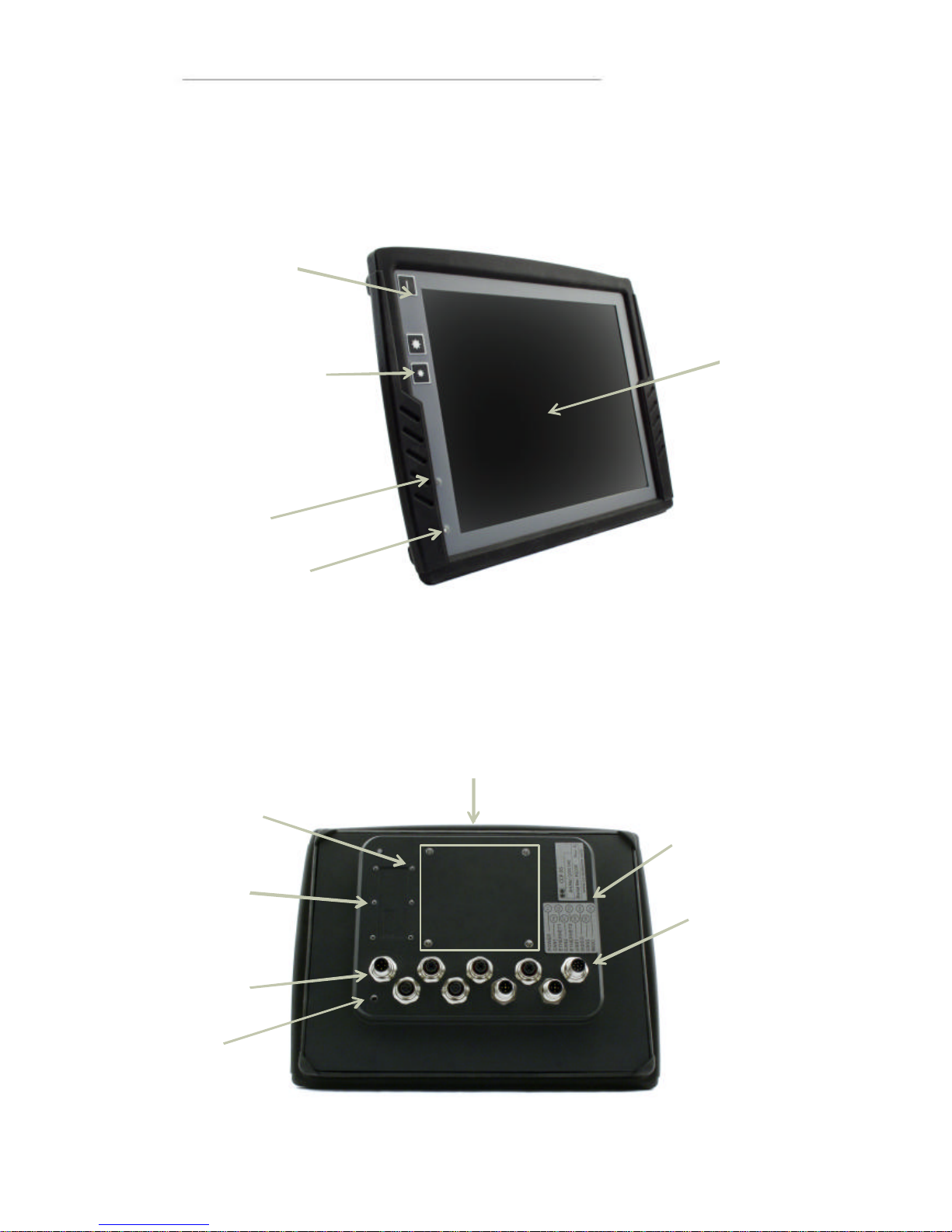
CC Pilot™ XS Front Face
On the front face of the CC Pilot™ XS there are the touch screen, a button for switching the
unit on/off as well as buttons for adjusting the screens brightness level. Furthermore, there
is a status indicator and a light sensor to aid in adapting the screen’s brightness level.
CC Pilot™ XS Rear Side
On the rear side of the CC Pilot™ XS there are the external connectors, which are
described in more detail in the chapter entitled Connectors On the rear side, there are
also mounting holes for fasteners in accordance with VESA 75.
Touch screen
Status Indicator
Light Sensor
Incr
ease and
decrease the
display’s
brightness level
On/Off
button
Mounting Holes, VESA
75
Brand Label
Connector Legend
External connectors
Ground
A
ntenna
connectors
Place for SM
card
Page 8

User Manual and Reference Handbook for the CC Pilot ™ XS
8
CC Pilot™ XS
Set-up and configuration
The CC Pilot™ XS use s Windows® CE 5.0 as operating system, which enables the
use of a multitude of applications in various fields of interest. Even though CC Pilot™
XS has been designed to handle greater stress and a harsher surrounding environment
than ordinary computers, it is built to be as simple as possible to handle. For instance,
through turn-key functionality, which means that the CC Pilot™ XS starts up
automatically when the key is turned in the ignition switch.
CC Systems AB can not guarantee the functionality for your CC Pilot™ XS in the case
where the supplied software is replaced or completed with other software which has
not been recommended by CC Systems AB or your supplier. Furthermore, CC
Systems AB can not guarantee the functionality of external devices, connected to your
CC Pilot™ XS.
Preliminary configuration
Depending on which particular situation your CC Pilot™ XS is being used; there can be
a need to perform an initial system and program installation. This can be true especially
with pre-installed software on the on-board computer or in the case where you yourself
installed new software. You have received instructions from you supplier and we
recommend that you abide by them in order to configure your system before use.
If you have received separately-supplied software that shall be installed in the onboard
computer, the CC Pilot™ XS may require synchronisation with a PC to install the
program. See the chapter entitled Software for more information about how you
connect to the CC Pilot™ XS.
Page 9

User Manual and Reference Handbook for the CC Pilot ™ XS
9
CC Pilot™ XS
Basic operations
This section covers basic operation of the CC Pilot™ XS unit such as start-up shut
down. For more information on usage please also see the Software chapter.
Function of the Display’s Push-buttons
In the top left corner of the CC Pilot™ XS there are three buttons:
On/Off Button
The unit starts up or is shut down by pressing this button. For more information about
starting up and shutting down the CC Pilot™ XS see the chapters called Starting Up
and Shutting-Down.
Brightness
There are two buttons to gradually increase or decrease the display’s brightness.
Starting Up
Start the unit by pressing and releasing the On/Off button. The status indication LED
will start flashing indicating that the unit is starting up
The unit can also be started by using a turn key functionality controlled from the power
connector on CC Pilot™ X S. For more information see the chapter
On/Off button
I
ncrease Display’s
Brightness
Decrease Display’s
Brightness
Status Indicator
Light Sensor
Page 10

User Manual and Reference Handbook for the CC Pilot ™ XS
10
Connecting the Power Supply.
Status Indicating Function
On the front side of the CC Pilot™ XS there is a status indicator, a red LED, which is
used to indicate different states for your CC Pilot™ XS during start up.
A 1Hz flashing red light indicates that the unit is starting up normally.
A continuous red light indicates something is wrong.
A quickly-flashing red light means that the unit’s disc is blank and
needs to be loaded with an operating system.
When the operating system starts, the LED stops flashing. From the operating system,
the LED can be used to show more messages. For more information, refer to the
operating system’s manual and also to the respective manual for each program
installed.
Shutting- Down
To ensure that data does not get lost or the hard disk become corrupt, it is
recommended that all programs are closed before the unit is shut down.
There are three ways to turn off CC Pilot™ XS:
By pressing the On/Off button on the display.
By selecting Suspend on the start menu of Windows CE
By releasing the power connectors On/Off signal, i.e. using the turn key
functionality
When performing any of above the system will CC Pilot™ XS start to shut down. In
order to help prevent data loss when the CC Pilot™ XS is shut down, there is a safety
mechanism in the system, which prevents the unit from shutting off before data has
been saved. This requires that the software which is running supports this.
Forced Shut Down
If the computer is not responding, press and hold the On/Off button for five seconds in
order to perform a forced shut down off the onboard computer.
Note that any information which was not saved will now be lost.
Touch screen
The CC Pilot™ XS is fitted with a touch screen which gives the opportunity to provide a
very easy -to-use HMI (Human Machine Interface) for the user. The first time the touch
screen is touched will cause a calibration routine to run. If needed, Calibration can also
be started manually via the control panel: start stylus, chose the tab Calibration and
then press the button Calibrate. Calibration can be cancelled by pressing the escape
key on a connected keyboard.
Be thorough with this calibration so that your touch screen will have the best possible
performance. You should use the same object (finger, stylus) during calibration which
you think you will use later.
Page 11

User Manual and Reference Handbook for the CC Pilot ™ XS
11
Don’t use sharp or pointed objects on the touch screen since these can damage or
scratch it, which can seriously degrade its functionality.
Reset of the unit
Using the On/Off button in combination with the brightness buttons it is possible
perform three modes of advanced start ups, forcing registry clean and formatting of
Compact Flash .
Make sure to back up any critical data before performing the steps below.
Clear the registry
1. Turn off the unit
2. Press the Power On button
3. Press the backlight increase key for about 2 seconds and the LED turns red
4. Press the backlight decrease key once
5. The LED starts to blink with a rate of 1Hz
6. Wait until the unit has finished its booting sequence
7. The registry is now restored
Format the Compact Flash (Hard Disk) storage memory
To format the Compact Flash perform the step 3 and 4 described in cl eaning the
registry 2 times, i.e. press increase, decrease, increase and decrease keys. The disk
will get the format FAT32 and TFAT.
Page 12

User Manual and Reference Handbook for the CC Pilot ™ XS
12
CC Pilot™ XS
Module description
This section deals with the various parts which make up the CC Pilot™ XS and how
they are used. Depending on your CC Pilot™ XS version Basic, Extended or AllIntegrated the configuration this section can handle functions and interfaces which are
not applicable to your unit.
The different versions are marked with:
• CC Pilot™ XS Basic
• CC Pilot™ XS Extended
• CC Pilot™ XS All-Integrated
Storage memory
For storage, a Compact Flash memory card is used, which is a type of non-rotating
hard disc drive. With this method, the CC Pilot™ XS is nearly insensitive to vibrations
which can be a problem when using rotating hard discs.
Besides the hard disc, there are also other types of memory in CC Pilot™ XS: RAM
and Kernel Flash. RAM memory is used by applications and the OS when the
computer is running. This memory is not persistent and will loose its information
whenever the computer is shut down.
The Kernel Flash memory is where the operating system is loaded, which differs from
ordinary computers where the operating sy stem is stored on the hard disc.
CAN
It is possible to connect two CAN-channels to the CC Pilot™ XS to connect a control
system or, for example, the FMS system in a vehicle. The contact for CAN-connections
follows the CANopen standard. CAN-drivers are installed on the onboard computer and
are included, in this case, with the delivery. CC Systems AB is well-experienced with
control via the CAN-interface and both software and drivers are tested in various
environments and under different conditions. Contact CC Systems AB if you need more
information about our CAN-solutions.
Ethernet
With an Ethernet connection, the CC Pilot™ XS can access other units and network s.
The CC Pilot™ XS has support for double Ethernet connections which allows it to, for
instance, act as a gateway in an embedded system.
Be aware that connecting CC Pilot™ XS to a network en vironment can impose a
security threat. CC Pilot™ XS is in its default setup not secured from external entities
trying to access inbuilt network related functionality such as FTP or Telnet.
Page 13
User Manual and Reference Handbook for the CC Pilot ™ XS
13
USB
Via the USB port, you can connect a multitude of devices to the CC Pilot™ XS. For
some devices, however, drivers compatible with the operating system are required to
be installed in order for the device to function. In the Microsoft Windows CE operating
system, which comes standard with the CC Pilot™ XS, there is support for a standard
keyboard and mouse via USB.
COM
A COM-port with RS-232 support is available on CC Pilot™ XS. The COM-port is used
for, among other things, connecting serial devices and synchronising the CC Pilot™ XS
with a PC-computer.
Depending on the configuration of the MISC connector the external COM port will have
different level of signal supported. Please see the Connectors section for more
information.
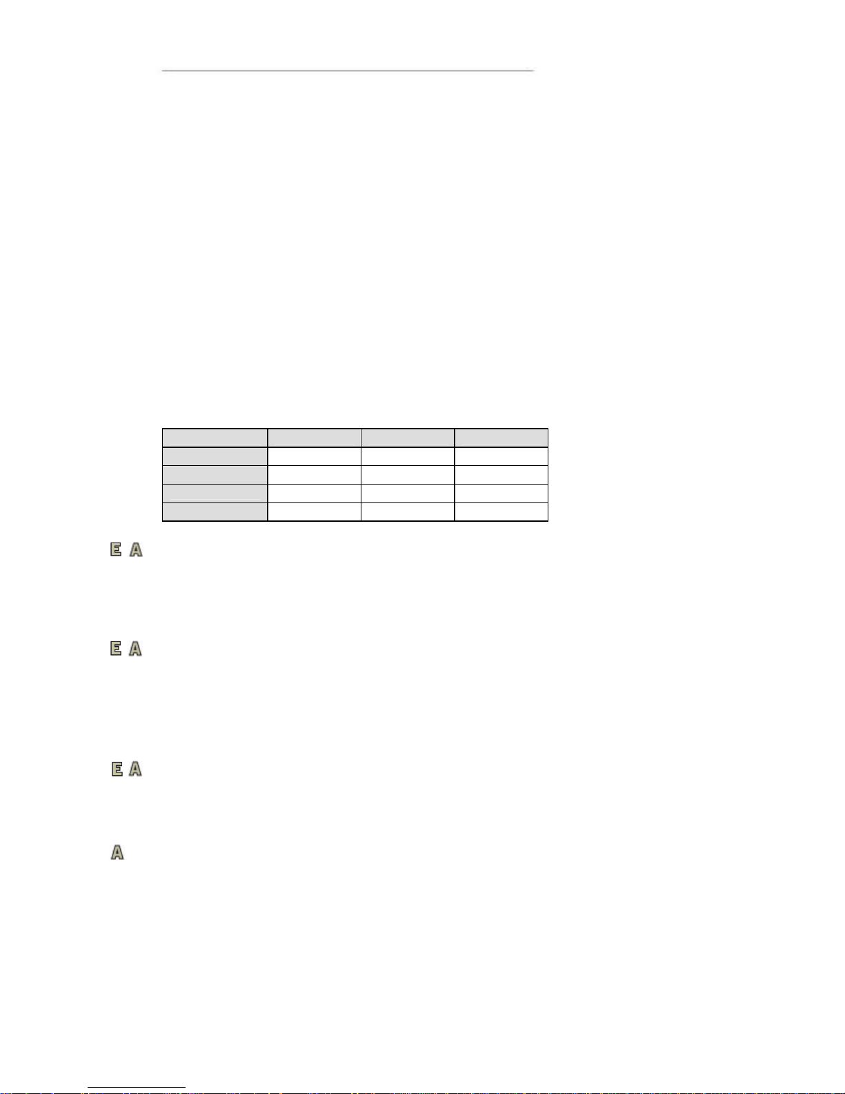
Besides the external COM-port there are two internal COM ports used when the CC
Pilot™ XS are equipped with the internal GSM/GPRS-modem, GPS and BlueTooth.
Function Basic Extended All-Integrated
External port COM 1 COM 1 COM 1
GPS
COM 2
BlueTooth
COM 2
GSM
COM 3
Digital Inputs
There are up to three Digital Inputs available on the CC Pilot™ XS Extended and AllIntegrated. The voltage range for a logic “Lo” signal is 0–0.8 V and logic “Hi” is between
2-36 V . There is no direct sampling of these inputs instead the actual values are polled
by the software.
Audio
Audio is available in the MISC connector on the CC Pilot™ XS Extended and AllIntegrated. The audio offers possibilities to play everything from warning sounds to
music direct ly from CC Pilot™ XS two channel speaker stereo output. Microphone in is
also available for sound recording or to present the sound from, for example, cameras.
Volume is set by the volume controls within Windows CE.
Video
On the CC Pilot™ XS Extended and All-Integrated there are connectors for two
composite video inputs for the attachment of video sources such as rear view cameras.
It supports PAL, the European video format, as well as NTSC, the American standard.
GPS
The internal GPS receiver in the CC Pilot™ XS All-Integrated follows NMEA-0183
standards. This standard is the most common on the market and most software which
uses GPS technology is compatible with the internal GPS receiver.
In order for the internal GPS unit to function, it requires a GPS antenna to be
connected to the GPS antenna connector on the CC Pilot™ XS and that the antenna is
mounted co rrectly.
Page 14

User Manual and Reference Handbook for the CC Pilot ™ XS
14
GPRS/GSM
The CC Pilot™ XS All-Integrated has an integrated GPRS/GSM modem for data
connection and access, for example, the internet or company network. The modem has
support for dual band (900/1800 MHz) and GPRS class 8 which gives a maximum
transfer speed of 85,6 Kbit/s.
The GSM/GPRS modem has a lower maximum operating temperature than the other
components in the on board computer. When the temperature goes beyond the
operating range for GSM/GPRS, the modem will automatically shut down.
Bluetooth
The CC Pilot™ XS Extended has built in support for SPP Bluetooth. SPP stands for
serial port profile and can be used as a wireless serial port extender.
Using SPP Blutetooth communication data sent to the internally connected serial port
are transparently forwarded to another Bluetooth module with serial port profile
Page 15
User Manual and Reference Handbook for the CC Pilot ™ XS
15
CC Pilot™ XS
Connectors
Connectors
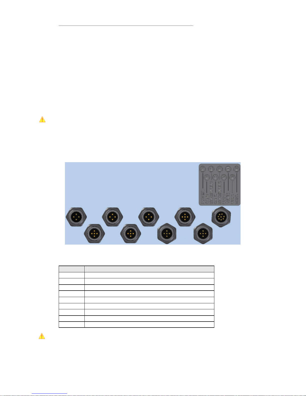
Accessible on the rear and top of CC Pilot™ XS, there are a number of ports to
connect various peripheral equipment. In order to give the CC Pilot™ XS its high
environmental classification, the unit is equipped with DIN M12 connectors. CC
Systems AB provides adapters which convert from DIN M12 to standard connectors.
Use caution when plugging/unplugging connectors. If the pins become bent or
damaged they may not function correctly, or in the worst case, the onboard computer
or other equipment may be damaged.
The connector legend describes where the connectors are located on your unit. On the
top of the unit there are also connectors for the GPS antenna and GSM/GPRS modem.
The connectors available is dependent on the unit’s configuration, it can therefore
address connections which may not be available to your unit
The table below describes the connectors on the CC Pilot™ XS.
Position Description
X1 Power Supply
X2 Ethernet1
X3 Ethernet2
X4 Video
X5 MISC (COM, Audio and/or Digital In
X6 CAN1
X7 CAN2
X8 USB1
X9 USB2
Notice that the following connector descriptions are those which are located on the unit,
not those that the attached cables shall have in order to mate with them.
Page 16
User Manual and Reference Handbook for the CC Pilot ™ XS
16
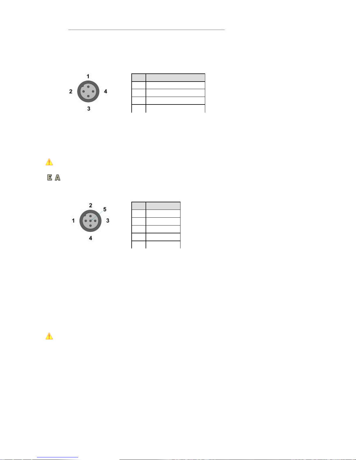
Power Supply Connector
Marking: X1 POWER
Connector Type: DIN M12 4-pole, A-coded, male
The CC Pilot™ XS power supply can range from 10 – 36 volts. If the power supply
voltage goes beyond this range, the unit shuts down. In order to ensure stable
operation with tolerance against temporary supply disruptions, the supply voltage
should be at least 12 V.
For complete hook up instructions, see the section entitled Installation.
Video (Video1, Video2)
Marking: X4 VIDEO
Connector Type: DIN M12, 5-pole, A -coded, female.
The connector is used to take in video signals of the type composite video. They are
PAL- and NTSC-compatible.
The video connector can be used to power external using the the12V unfiltered supply.
The output has a current limit that depends on the internal unit temperature. The current is
limited to 0.150A at an internal unit temperature of 70 degrees Celsius and around 0 .2A in
normal working conditions.
The cable which is used to connect the camera to the computer shall be a 75-O coaxial
cable, e.g. M17/94-RG179.
Ensure that there is no DC-offset (supply current) on the video signal connected since
this can cause damage to your CC Pilot™ XS.
Pin Description
1
Battery(+28 VDC
) 2 ON/OFF (+28 VDC
) 3 GND
4
GND
Pin Signal
1
GND ch 1
2
Video ch 1
3
Video ch 2
4
12V 5 GND ch 2
Page 17
User Manual and Reference Handbook for the CC Pilot ™ XS
17
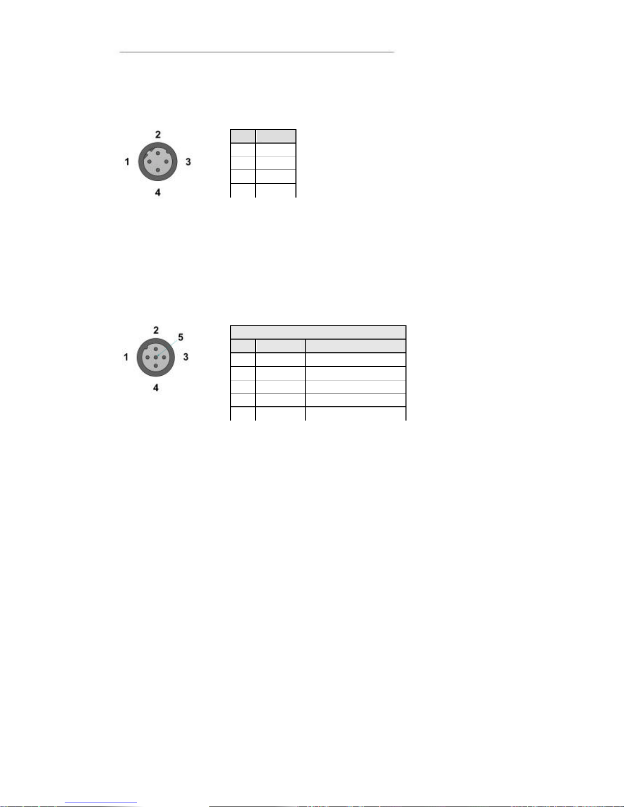
Ethernet (Ethernet 1, Ethernet 2)
Marking: X1 Ethernet1 and X3 Ethernet2
Connector Type: DIN M12 4-pole, D-coded, female
The ports support 10/100 Mbps, i.e. communication speed up to 100 Mbps.
CAN (CAN1, CAN2 )
Marking: X6 CAN1 and X7 CAN2
Connector Type: DIN M12, 5-pole A-coded, female
The CAN connector follows the CANopen standard
The interface has a PCA82C251 high speed transceiver installed and follows the ISO
11898-24V standard. There is no termination in the interface; therefore, this shall be
present in the cable.
The CAN connectors can be used to supply power to external units using pin 2 and 3. The
output has a current limit that depends on the internal unit temperature. The current is
limited to 0.31A at an internal unit temperature of 70 degrees Celsius.
Protection against external voltage (up to 40V) higher than the supply voltage is provided
from a diode in series with the output. The supply voltage will be the same as the filtered
supply to the CC Pilot™ XS with an additional voltage drop over the diode in series, i.e. the
output voltage will be about 23 volts when 24 volts is supplied.
Pin Signal
1 TX+
2 RX+
3 TX 4 RX-
CAN 1 & CAN 2
Pin Signal
Description
1 -
No connection
2
CAN V+
8-
36 V Out
3
GND
4 CAN1 H
CAN High bus line
5
CAN1 L
CAN Low bus line
Page 18
User Manual and Reference Handbook for the CC Pilot ™ XS
18
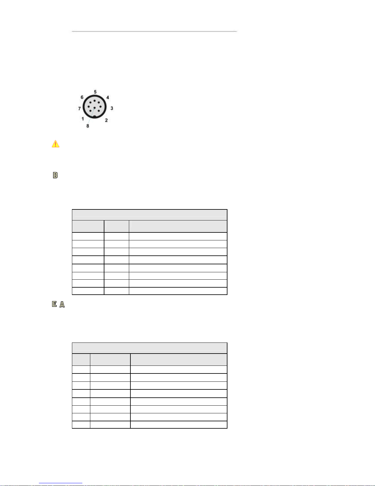
Misc Port (COM1) Alternatively: Audio, Communication and or Digital Input
(MISC)
Marking: X5 MISC
Connector Type: DIN M12, 8-pole, A -coded, male.
NOTE! This connector has two alternative functions depending on the configuration
ordered. The connector can be either as an communication (COM) port or as a
combination port with Audio, Digital Input and communication (COM) port.
The configuration is factory set and can not be changed.
COM port
When configured as a serial com port the signal “Ring Indicator” has been omitted,
which means that peripherals which require this signal will not work. The rest of the
COM port follows the RS232 standard, so peripherals which follow this standard can be
connected. The supported communication speed for these ports is 2.4 to 115.2 kbps.
COM
Pin Signal Description
1 DCD Data Carrier Detect
2 RxD Receive data
3 TxD Transmit data
4 DTR Data Terminal Ready
5 GND Signal reference
6 DSR Data Set Ready
7 RTS Request To Send
8 CTS Clear To Send
COM, Audio and Digital in
When X5 is configured as a combination of COM, audio and digital in the port will have
a limited COM port with only send and receive data signals. The port will also include
two channel audio out, microphone in and two channel digital in.
Audio & Digital Input
Pin Signal Description
1 Audio Out L Left channel audio out
2 Audio Out R Right channel audio out
3 TxD Transmit data
4 Microphone Microphone audio in
5 GND
6 Digital Input (0-36 VDC)
1)
7 Digital Input (0-36 VDC)
1)
8 RxD Receive data
Page 19
User Manual and Reference Handbook for the CC Pilot ™ XS
19
USB
Marking: X8 USB1 and X9 USB2
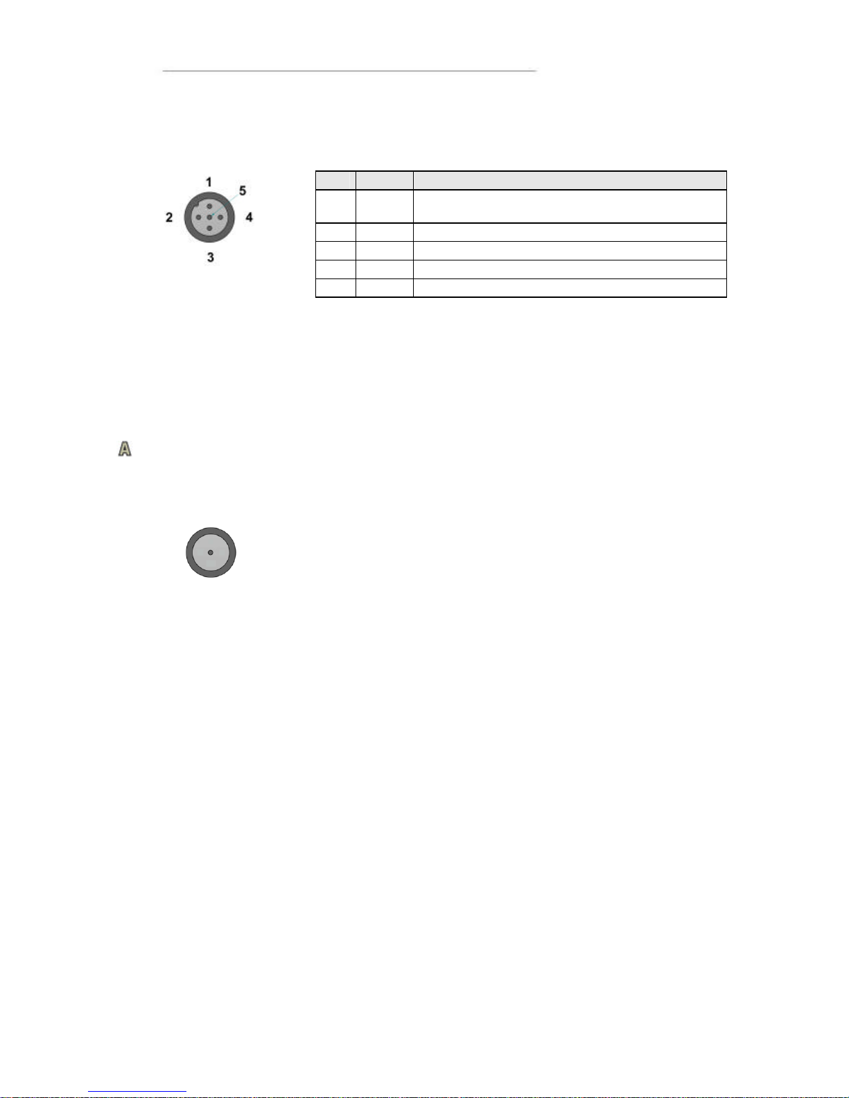
Connector Type: DIN M12, 5-pole, A -coded, male
The two USB ports follow the USB 2.0 standard with a transfer speed of up to 480
Mb/s. The USB ports are also compatible with the USB 1.1 standard. Both USB ports
operate in host mode.
The power supply follows the USB standard, which means an output voltage of +5 V
and maximum current of 0.5 A per port. Note that if too much current is drawn, the
built-in safety will shut off the USB port(s).
GSM/GPRS-antenna
Marking: GSM
Connector Type: SMA, female
This connector is used to attach the antenna to GSM/GPRS modem. The cable which
is used to connect the GSM/GPRS antenna to the computer shall be a 50-O coaxial
cable which has low attenuation at high frequency (˜ 1.5 GHz).
Pin Signal
Description
1 Vbus
Power supply to external USB unit. 5 V,
500mA max, Internal short-circuit and overload
2 D- Data
3 D+
Data
4 -
No connection
5
GND
Page 20

User Manual and Reference Handbook for the CC Pilot ™ XS
20
GPS-antenna
Marking: GPS
Connector Type: SMA, female
This connector is used to attach the antenna to the GPS receiver. The cable which is
used to connect the GPS antenna to the computer shall be a 50-O coaxial cable which
has low attenuation at high frequency (˜ 1.5 GHz).
The voltage supported for active antennas is 3.3 V DC.
Bluetooth-antenna
Marking: Bluetooth
Connector Type: SMA, female
This connector is used to attach the antenna for the Bluetooth.
Page 21
User Manual and Reference Handbook for the CC Pilot ™ XS
21
CC Pilot™ XS
Installation
Your CC Pilot™ XS must be installed in such a way that the unit is not exposed to any
unnecessary stress or present any traffic danger. In this section, some
recommendations are made regarding methods for how the unit should be i nstalled.
CC Pilot™ XS shall only be installed and serviced by authorized personnel. If the unit is
opened by non-authorised personnel, the warranty becomes void.
Placing and installing of the unit and peripherals
The CC Pilot™ XS shall be installed in a ventilated space where air is able to circulate
around the unit, therefore not near hot air vents or the like. If the unit becomes too
warm, it may not perform to its full capacity and, with high temperature, cease to
function.
If the preceding instructions are not observed, the cooling of the unit can be degraded
which can lead to overheating, consequently causing permanent damage to the unit.
When the CC Pilot™ XS or any device is installed it is important to do so in such a way
that the installation is traffic -safe. One should also avoid installing the unit where it will
block the driver’s view. This applies to both the instrument panel and the view through
windshield. One should also think about how the placement affects personal safety in
the event of a collision.
We recommend installing CC Pilot™ XS in such a way that it is not exposed to
unnecessarily vibration or other stress.
Bracket Mounting
The CC Pilot™ XS is preferably mounted on a convenient bracket which allows for
adjustment of the display’s position and angle. The bracket should have, or be provided
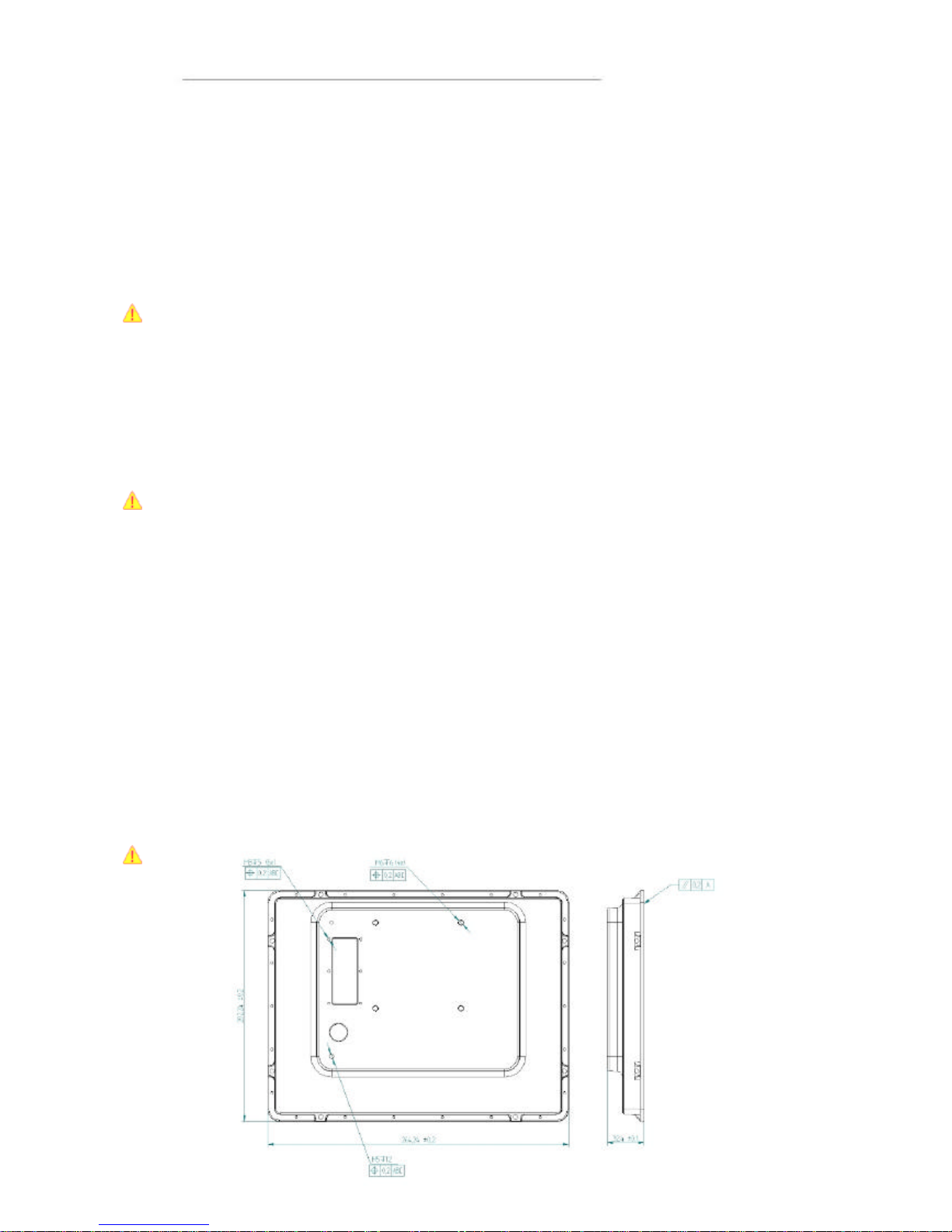
with, a flat fastening plate to which the unit is bolted (VESA 75). To fasten, use the
appropriate M6 cap screw of type MC6S (Allen) or MRT (Torx). Note that the enclosure has
blind holes, which give a maxi mum thread depth in the enclosure of 6.5 mm. The maximum
torque is 2.5 N-m. Apply a thread locker in all bolt holes, e.g. Loctite 222.
Page 22
User Manual and Reference Handbook for the CC Pilot ™ XS
22
Panel Mount
There are two installation alternatives for panel mounting: front-mounted or rearmounted.
With a front-mounted installation, use the rubber mask as a seal against the panel
plate. The unit is locked down by applying clamps which are either fixed to the panel
(recommended) or fixed to the unit through holes for VESA75 installation.
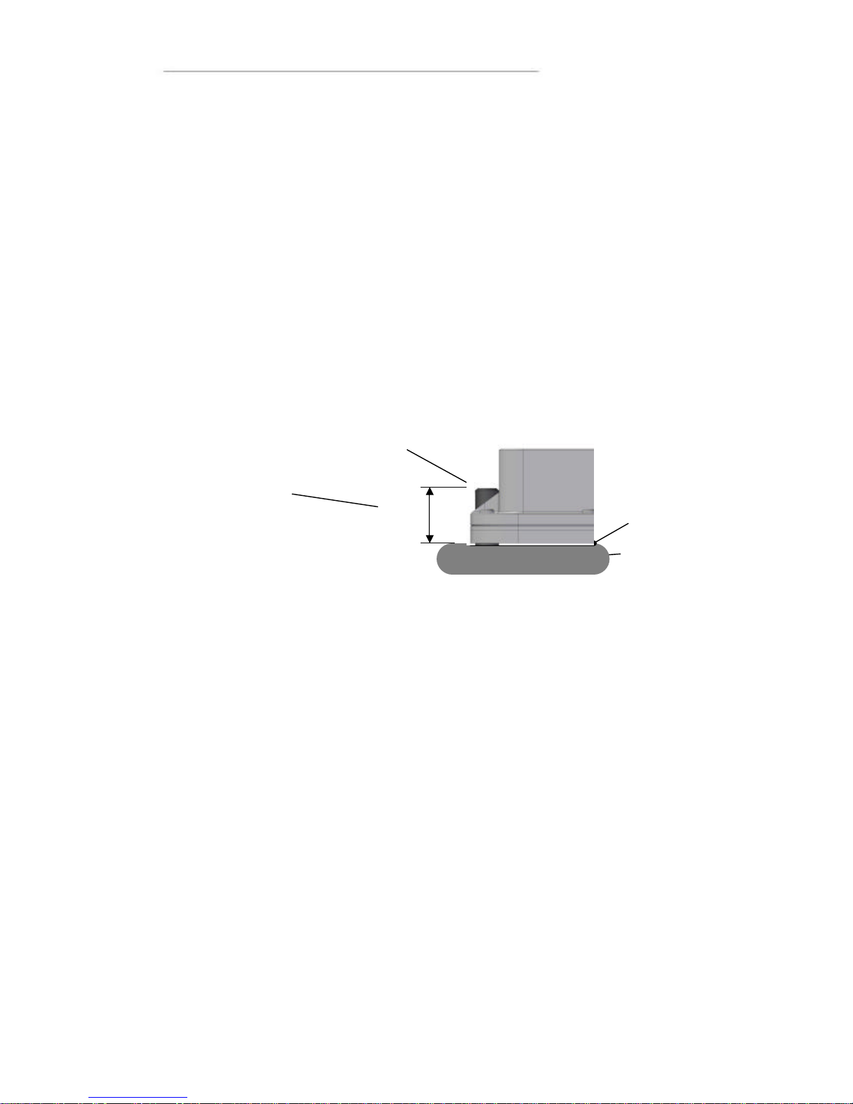
By replacing the rubber jacket on the unit with a cut-out rubber gasket, the CC Pilot™
XS can also be rear-mounted inside a suitable panel or equivalent. For this, the eight
fastening holes are used, see the figure below. As a fastener, appropriate machine
screws of type MRT M5 or MC6S M5 can be used. The maximum torque is 2.5 N-m.
If the surface against which the unit will be fastened is not flat, one must be careful so
that so that one does not expose the unit to mechanical stress due to tightening . This is
suitably solved through applying appropriate spacers between the unit and the surface
being attached to. As an alternative, a separate flat fastening plate can be used for the
unit. This is then attached with separate screws, or some type of fasteners, to the
panel. Use a thread locker in all screw holes, e.g. Loctite 222
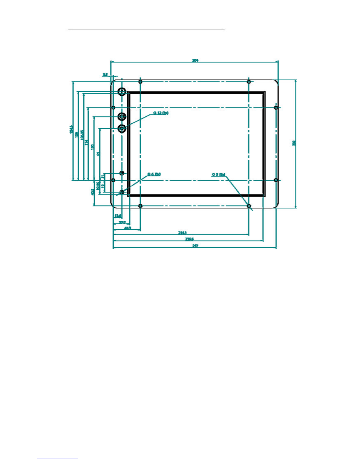
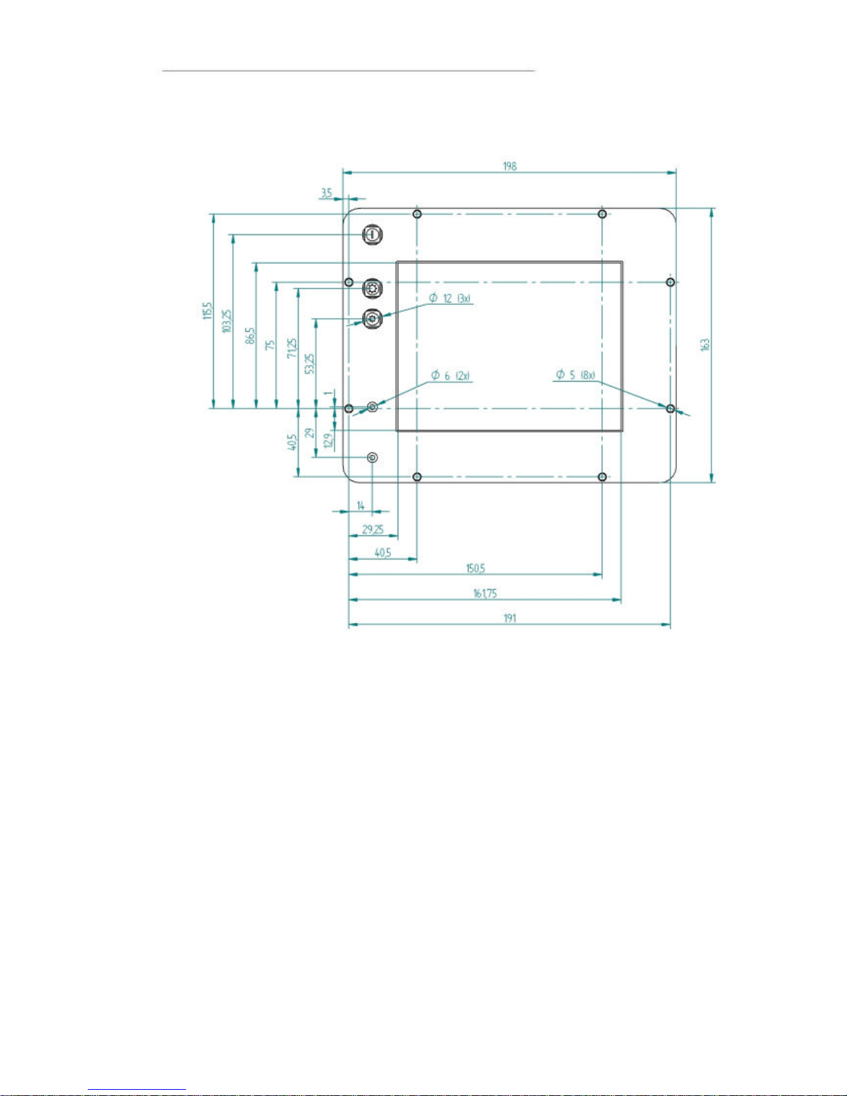
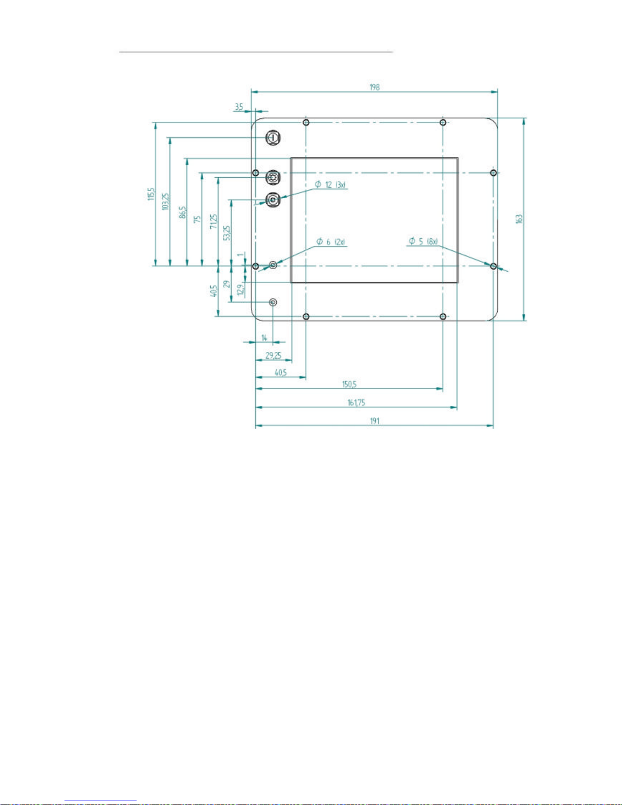
The drawing above illustrates the spacing of the eight mounting holes for panel
mounting from the rear. The drawings below show unit dimension, mounting holes
placement and cut out for display, buttons and indicators. For other dimensions please
see the section weight and dimensions.
Min
12 mm
The cap screws
should extend at
least 12 mm
beyond the
Panel Plate.
Panel
Plate
M5
Cap Screws
,
8 pcs.
Gasket
Page 23
User Manual and Reference Handbook for the CC Pilot ™ XS
23
Display Panel Dimensions for 10,4”
Page 24
User Manual and Reference Handbook for the CC Pilot ™ XS
24
Display Panel Dimensions for 6,5”
Page 25
User Manual and Reference Handbook for the CC Pilot ™ XS
25
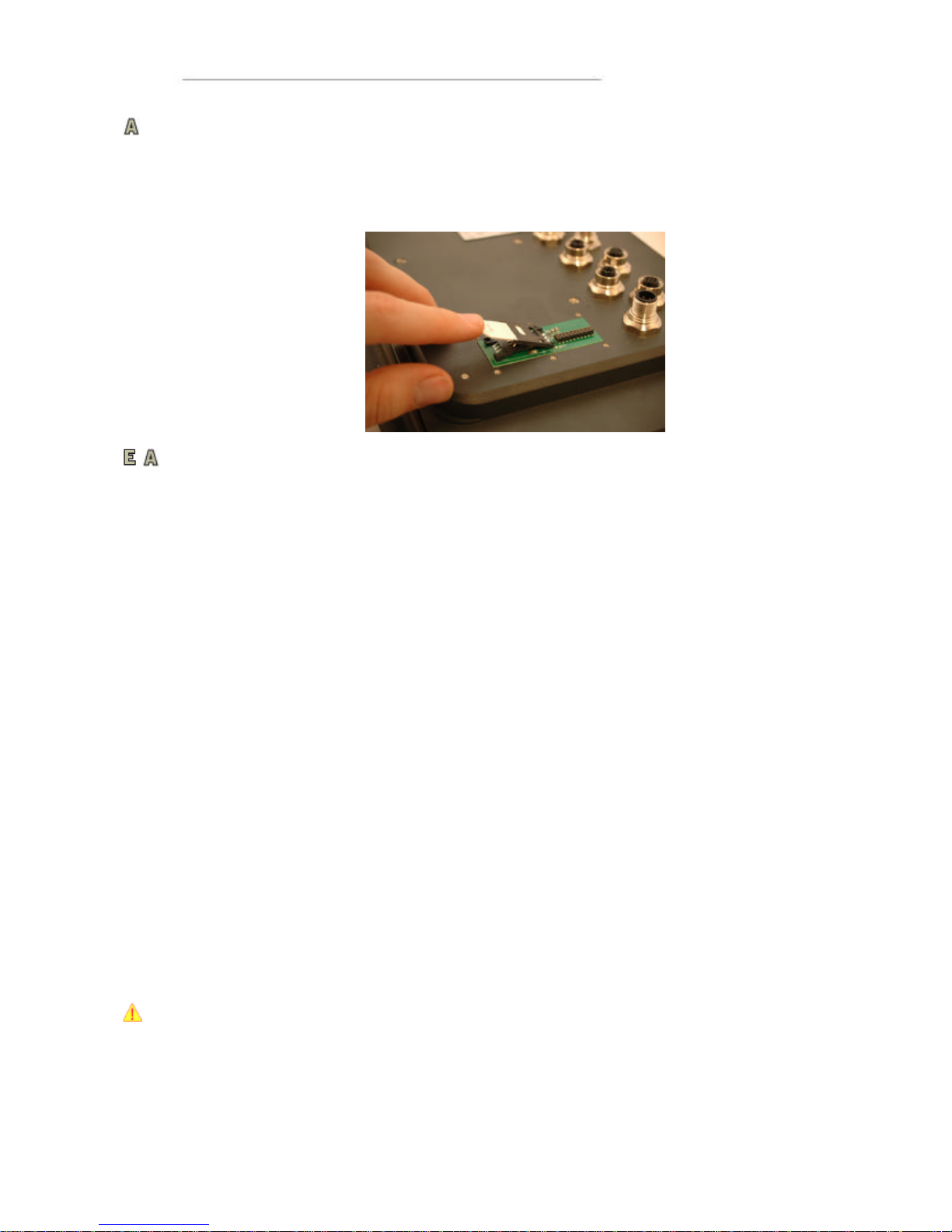
Installing the SIM card
The SIM card is installed in a SIM card holder under the SIM card cover. Install the
SIM -card by unscrewing the six screws holding the SIM card cover and lift the cover
away. Open the flap on the SIM card holder and place the SIM card into the holder,
being careful to slide the card all the way into the holder. Close the flap. Reinstall the
SIM card cover.
Installing the Antenna
Antennas for GPS, GSM/GPRS and Bluetooth can be mounted on the vehicle’s roof or
inside the vehicle’s cabin (e.g. in the windshield). Mounting inside the cabin, however,
degrades the reception. The reception is degraded further in vehicles which have
electrically-heated windshields. Attach the antenna cables to their respective contact
on the unit’s top side. See chapter Connectors for the right choice of antenna cables
and connectors.
For best performance the GPS antenna requires a free viewing angle towards the sky
which covers 130° and that it is mounted at least 400 mm from any other radio
antennas, e.g. FM-antenna.
Cables
Cables shall be installed so that they don’t run the risk of being damaged, pinched or
worn. Avoid bending and twisting cables. Strain-relief on cable assemblies shall be
arranged near the connection to the respective unit. This is in order to avoid stress to
the unit’s contacts. The connectors shall always be screwed-in securely to give good
contact and avoid unnecessary strain.
Through adapter cables, as supplied by CC Systems AB, standard connectors for
Ethernet, USB and COM can be connected to the unit. The hook up of these adapter
cables can and should be placed in a moisture-free, hidden space and should be
secured and strain-relived.
Keyboard and Pointing Device
The Keyboard and Pointing Devices connected to CC Pilot™ XS must support
connection via USB. CC Systems AB offers devices intended for the CC Pilot™ XS.
The keyboard and Pointing Device should be placed in a location that is easily-
accessed, but not in the way when they are not being used.
Consider traffic safety whenever the CC Pilot™ XS is installed and used in vehicle
installations. CC Systems AB does not recommend that the CC Pilot™ XS or its
accessories are used actively by the driver when a risk of injury to people, or damage
to property, is present.
Page 26
User Manual and Reference Handbook for the CC Pilot ™ XS
26
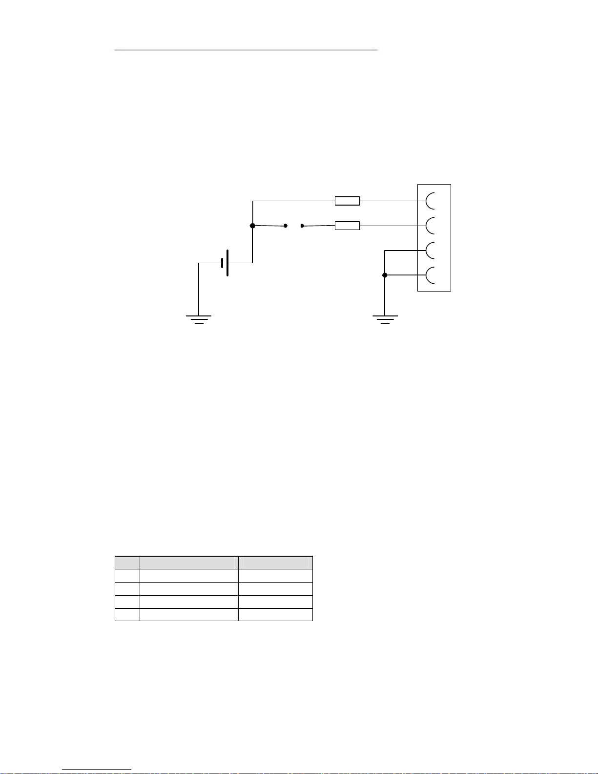
Connecting the Power Supply
This instruction addressed vehicle installations but the principle is the same also for
other types of installations. See also the description of the pinouts for the Power Supply
Connector under the section Connectors.
Carefully observe the connection diagram below. Ensure that their plugs are turned the
right way around and that they are not forced in but lock together smoothly and easily.
GND is connected to the vehicle’s ground.
Battery (pin 1), i.e. the computer’s power supply (+28 VDC) is coupled directly to the
vehicle’s battery (BATTERY) through a 5-A fuse (F1). If applicable connect the on
board computer before any main switch, as per the illustration above.
ON/OFF (pin 2), i.e. the computer’s on/off signal is connected though a 5-A fuse (F2) to
the battery. If the vehicle has a main power switch (S1, MAIN SWITCH) the computer
shall be connected after it, as in the illustration above.
By connecting the power supply according to the illustration above, the vehicle
computer will automatically start when the main switch is turned on, and shut down
when the switch is turned off. While the main switch is in the ON position, the onboard
computer can be turned off and on with the On/Off-button.
The Power Supply Cable’s leads, which are supplied by CC Systems AB, are colourcoded according to the table below.
Pin Signal Colour Coding
1 Battery (+28 VDC) Brown
2 ON/OFF (+28 VDC)
White
3 GND Blue
4 GND Black
GND 1 2 3 4 F1 5A F2
GND BATTERY
S1 PS
MAIN SWITCH
Page 27

User Manual and Reference Handbook for the CC Pilot ™ XS
27
CC Pilot™ XS
Software
This section gives a short description to some of the software supplied with the CC
Pilot™ XS.
Operating System
The CC Pilot™ XS is supplied with the Windows CE operating system and this manual
provides the basics how to get started with basic operations and configurations.
Windows CE resembles and behaves a lot like Microsoft’s Windows operating system
for the personal computer. But there are fundamental differences. Windows CE is built
up in another way and is intended for other types of units than the PC platform. This
means, among other things that programs intended for a PC running windows won’t
work on Windows CE.
There are several versions of Windows CE and for several different processor families.
In order for third party products to function on the CC Pilot™ XS, the application must
be built for XScale, or alternatively, ARM processors as well as be built for the version
of operating system which the unit is equipped with.
The CC Pilot™ XS offers a multitude of connection alternatives, for instance via, USB.
In order for the device connected to CC Pilot™ XS to function correctly, sometimes
drivers must be installed. CC Systems AB can only guarantee the function for
applications and devices which are tested and approved by CC Systems AB.
Getting Started with Windows CE
The following section will provide essential information to get you started using CC
Pilot™ and performing basic configuration of the Windows CE on CC Pilot™
Page 28
User Manual and Reference Handbook for the CC Pilot ™ XS
28
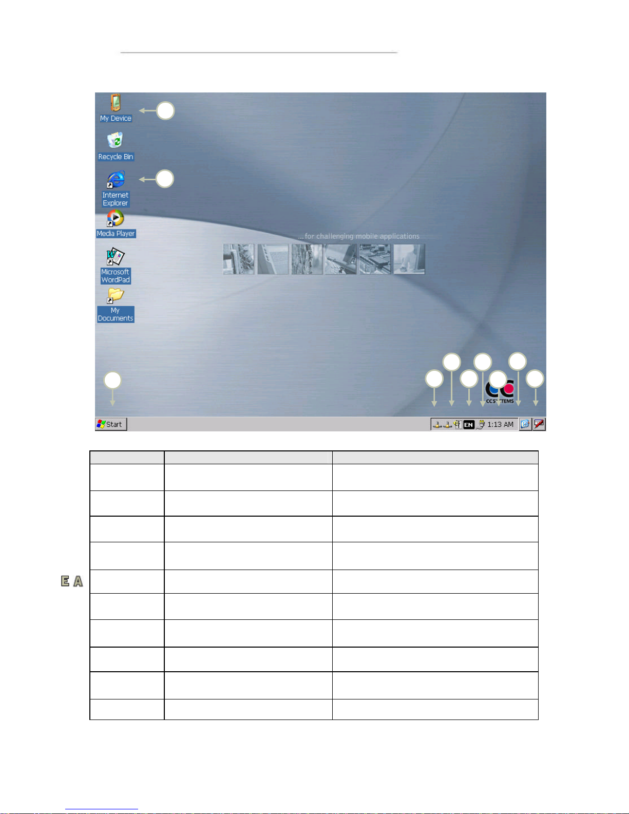
The Desktop
Nr Name
Description
1
My Computer
To access the computer’s hard disc
(Compact flash)
2
Internet Explorer
To access the internet browser
3 Start button
To start programs and access the
Control Panel
4 Network status
Information about the network connection
and access to network se ttings
5 Volume control Access to the volume control
6 Input language selection
Information about what input language is
used
7 Status for Power Supply
Information about the po
wer supply and
setup for energy saving features
8 Clock
Shows the time, and allows time and
date to be set.
9 Minimises all wi ndows
Minimises all windows which are visible
on the desktop
10 Input panel Access the virtual desktop and its setup
9
2 3 4 1 6 7 8 10 5
Page 29
User Manual and Reference Handbook for the CC Pilot ™ XS
29
Navigating the Desktop
Using the touch screen with a stylus or finger, one can navigate in Windows CE and
the applications being in use . Besides the touch screen, keyboard and mouse
connected via the USB port can also be used.
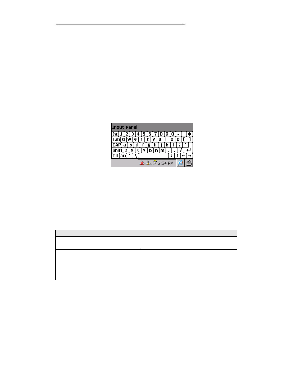
To input letters and symbols while using the touch screen, there is a virtual keyboard
called Input Panel . The Input Panel can be used either via the mouse or the touch
screen. The Input Pane l is started by pressing on its icon which is to the right of the
clock in the task bar. In the menu which is shown, choose keyboard to show the virtual
keyboard. Two sizes of keyboard can be chosen. The default setting is the small
keyboard. To view the larger keyboard, click on the icon for the Input Panel and chose
LargeKB.
To input specific local letters using the input panel, such as the Swedish å, ä, ö. Click in
the áü button where alternative letters are available.
Storing data
There are various possibilities to store data while working with the CC Pilot™ XS. In
contrast to the Pocket PC handheld computers, the CC Pilot™ XS works more like a
personal computer. When the computer is shut down, all applications shut down and
data that has not been saved is lost. Therefore it is important to know which memory
holds the stored information after power to the unit is switched off, the so -called static
memory. The table below describes storing possibilities in the CC Pilot™ XS. Besides
these one other types of memory can also be connected, such as USB memory sticks.
Type of
Name
Description
Compact flash
My
Device
Hard disc in the form of Compact Flash memory.
For permanent data storage, applications and
System me mory RAM
Used by the application that
is running. This
memory is not static and is erased when the unit
is shut down.
The Network Network Information can also be stored on other units via
the network.
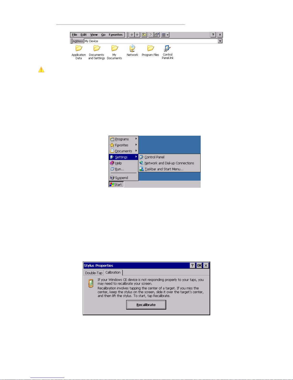
Use the Explorer to access files on the unit. There are several ways to start the
explorer, for instance by clicking on the icon My Device on the desktop. A window is
then shown similar to the picture below. Here, one can access the folders stored on the
Compact Flash memory. If other memory modules are attached, like for instance a
USB memory unit, this will also appear here.
Page 30
User Manual and Reference Handbook for the CC Pilot ™ XS
30
NOTE! To prevent the loss of information, which is stored on the hard disc, the unit
must be shut down correctly. If the unit shuts down incorrectly or the power is switched
off to the unit this can lead to corrupt files and damage to the hard disc.
The Control Panel
Settings in Windows CE can be changed through the Control Panel. Using the Control
Panel it is, for instance, possible to change the settings for the screen, network
connections as well as time and date.
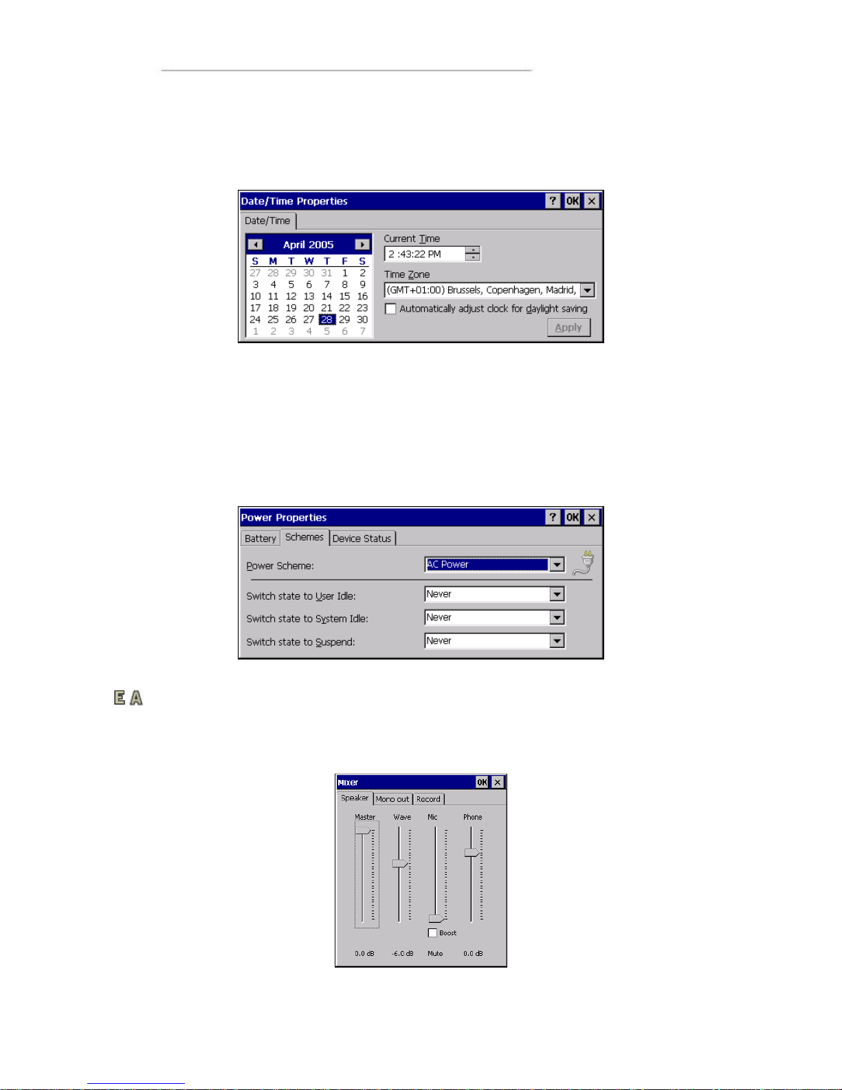
The Control Panel is activated from the start menu by clicking on the Start Button, then
choosing settings, and then Control Panel .
Calibrate the Touch screen
If the touch screen needs to be calibrated, the calibration routine starts automatically
when the touch screen is tapped. Follow the instructions as shown on the screen to
calibrate the touch screen. If the calibration does not succeed, the calibration routine
will start over. The calibration can be cancelled by pressing the Escape (Esc) button on
an attached keyboard.
The calibration routine can be started manually by selecting the alternative stylus on
the control panel. Chose the Calibration tab in the dialogue box as shown and press
the button Recalibrate.
Page 31
User Manual and Reference Handbook for the CC Pilot ™ XS
31
Set Time and Date
Open the settings for time and date through Date/Time in the Control Panel. Input the
date, time and time zone. Activate these settings by pressing the button Apply.
Configure Power Properties
Choose Power Properties on the Control Panel to chose which energy profile to be
used by your CC Pilot™ XS in different situations. For example, the brightness of the
screen can be reduced when the unit is not being used.
In the example below, Windows is configured to always have the screen on and never
go down into an idle state.
Adjusting sound level
If your CC Pilot™ XS is equipped with audio capabilities you will have a volume control
icon in the start menu bar. Clicking on this icon displays the volume controls. Use the
levers to adjust the volumes.
Page 32
User Manual and Reference Handbook for the CC Pilot ™ XS
32
Changing the input language
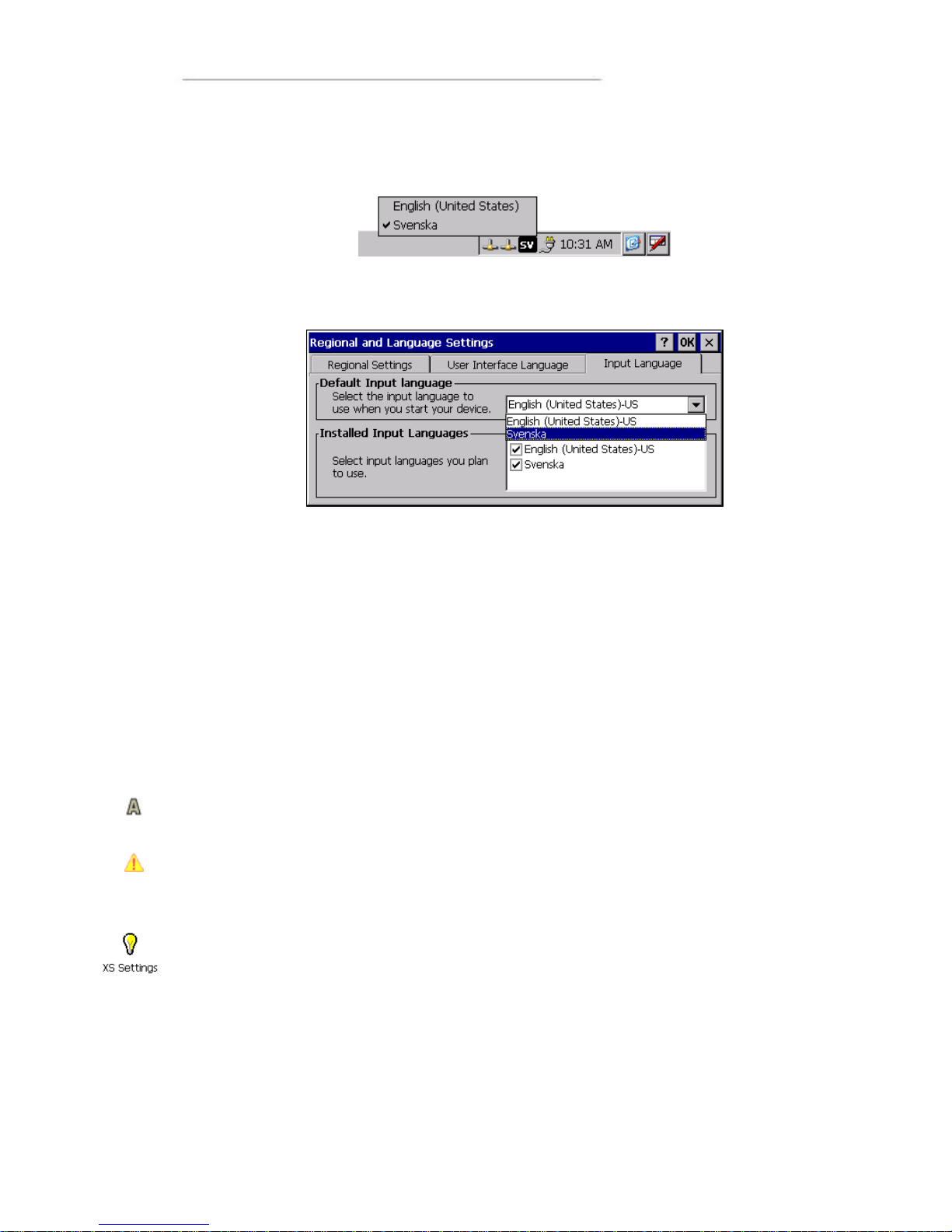
The toolbar shows the input language that is currently used. To temporarily change the
input language click on the icon and select the desired input language.
To permanently change the input langue, select Regional setting from the Control
Panel. In the Input tab select the desired default language.
Windows Help
The built-in help in Windows CE gives information about most functions and settings
within Windows CE and respective applications. Help is started though the Start menu
by choosing Help.
In many windows there is also a button with a question mark (?) in the upper right
corner. Click on it to directly come to the right se ction in Help.
Network Access
The CC Pilot™ XS can have up to two Ethernet connections for network access. To be
able to connect with a network it may be necessary to configure the network settings.
The default co nfiguration is to obtain settings using DHCP. To manually configure the
network settings, open Network Settings in the Control Panel. Contact your network
administrator for help with network settings.
There are also other ways to connect to a network, such as though dial-up connection
via the GSM/GPRS modem.
Be aware that connecting CC Pilot™ XS to a network environment can impose a
security threat. CC Pilot™ XS is in its default setup not secured from external entities
trying to access inbuilt network related functionality such as FTP or Telnet.
XS Settings
CC Pilot™ XS specific settings is configured using XS Settings. Using XS Settings
configuration options is accessible for CAN, GPS, GPRS, automatic backlight control
and power outlets. XS settings are accessed by opening XS Settings from the control
panel.
Some of the settings will not take effect until the system is restarted. XS settings will
inform if this is necessary upon pressing OK.
Page 33
User Manual and Reference Handbook for the CC Pilot ™ XS
33
CAN
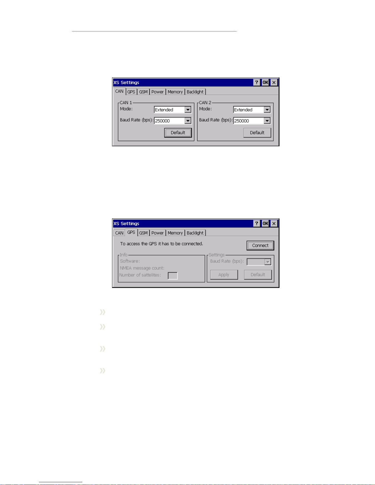
From the CAN tab, settings are made for CAN message frame mode and baud rate. By
pressing the default button the CAN settings will be reset to predefined default settings.
GPS
From the GPS tab, status can be read for the GPS and the baud rate of the GPS can
be altered.
To be able to get any information from the GPS it must be connected. Make sure all
other programs that use the GPS are closed then click Connect to establish a
connection. The connection procedure can take up to several minutes.
When connected the Info panel will give following information:
Software information of current software version in the GPS receiver.
NMEA message count this counter increases with one each times the
GPS sends out a me ssage with information.
Number of satellites is the number of satellites the GPS receives signals
from. This value is only valid if the NMEA message counter is counting.
Change baud rate by selecting the desired baud rate and click apply. Note
that the baud rate change will reset to default rate when the unit is
restarted.
Page 34
User Manual and Reference Handbook for the CC Pilot ™ XS
34
GSM
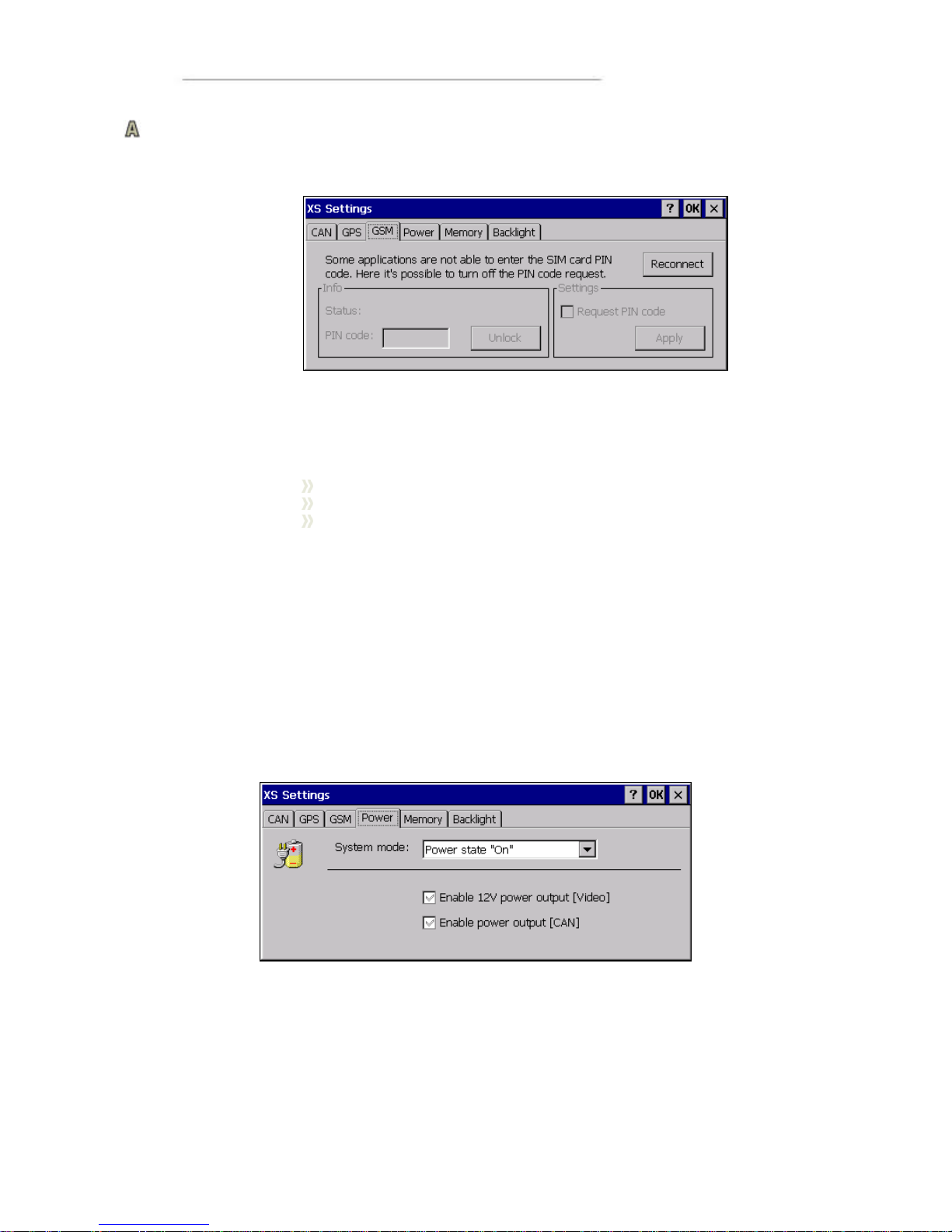
From the GSM tab status information are displayed for the GSM modem. From here it
is also possible to turn on or off the PIN code of the SIM -card.
To turn on or off the PIN-code please:
1. Make sure that all other programs that use the GSM modem are closed.
2. Select the GSM tab.
3. In the Info>Status information of the code status in presented.
ENTER PIN, the SIM card needs a PIN code.
PIN OK, the SIM card is unlocked.
--, An error has occurred.
4. If PIN code is needed for unlocking the card, enter the code in the PIN code field and
click Unlock.
5. To change the security level check or uncheck the Settings>Request PIN code and
click Apply. To be able to change the security level you always need to have the valid
PIN code entered in the PIN code field before clic king Apply.
Power
From the Power tab it is possible to control the power outlets on the unit. For more
information regarding supply levels of the power outlets see the Connectors chapter.
The power outlets can also be controlled by other applications or from the I/O-driver.
Therefore you must be careful when setting the power properties, not to interference
with any application or system requiring power out.
The power settings are set individually for each of Windows CE´s power states. In the
Power state dropdown list the power states are present. Select the state you want to
make the changes for. Check or uncheck the Video power enable and CAN power
enable checkboxes to select if the power supply shod be on or not
Page 35
User Manual and Reference Handbook for the CC Pilot ™ XS
35
On: black tick in the checkbox. The power output will switch on when the
system enters the particular system mode.
Off: empty checkbox. The power output will switch off when the system
enters the particular system mode.
Invalid: grey tick in the checkbox. No change will be made when going
into the particular sy stem mode. Use this option when other applications
are controlling the power output.
Be aware that putting a high load on the power outlets will result in a higher unit
temperature.
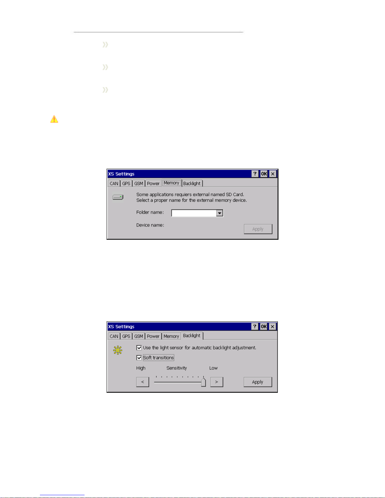
Memory
From the memory tab it is possible to select the name to be used for attached USB
memory units. Select the name to use from the folder name drop down list box.
Backlight
From the backlight tab it is possible to enable and adjust settings for the automatic
backlight control.
To enable or disable the automatic backlight control check or uncheck the checkbox
Use the light sensor for automatic backlight adjustment.
By selecting the soft transitions checkbox the backlight will slowly change intensity for
new light conditions.
Adjust the sensitivity of the backlight control by moving the sensitivity slider. By moving
the slider against low, a bigger change in surrounding light will be needed for any
change in backlight level and vice versa.
When enabling automatic backlight control, the brightness buttons at the front of CC
Pilot™ XS will change the offset of the backlight level. This offset is depending on the
Page 36
User Manual and Reference Handbook for the CC Pilot ™ XS
36
surrounding light; therefore the setting may vary depending on whether it is changed in
bright of dark environments.
CC Video
CC Video is the application used to view the video input signals from the video, X4,
connector on the CC Pilot™ XS. CC Video does only display this signal; please use the
Microsoft Media player to display me dia files and other video streams.
To enable usage of the video application in many environments, the CC Video can be
controlled in several ways, by the tool bar buttons, the menus, the pop up menu or by
an external application using a application interface.
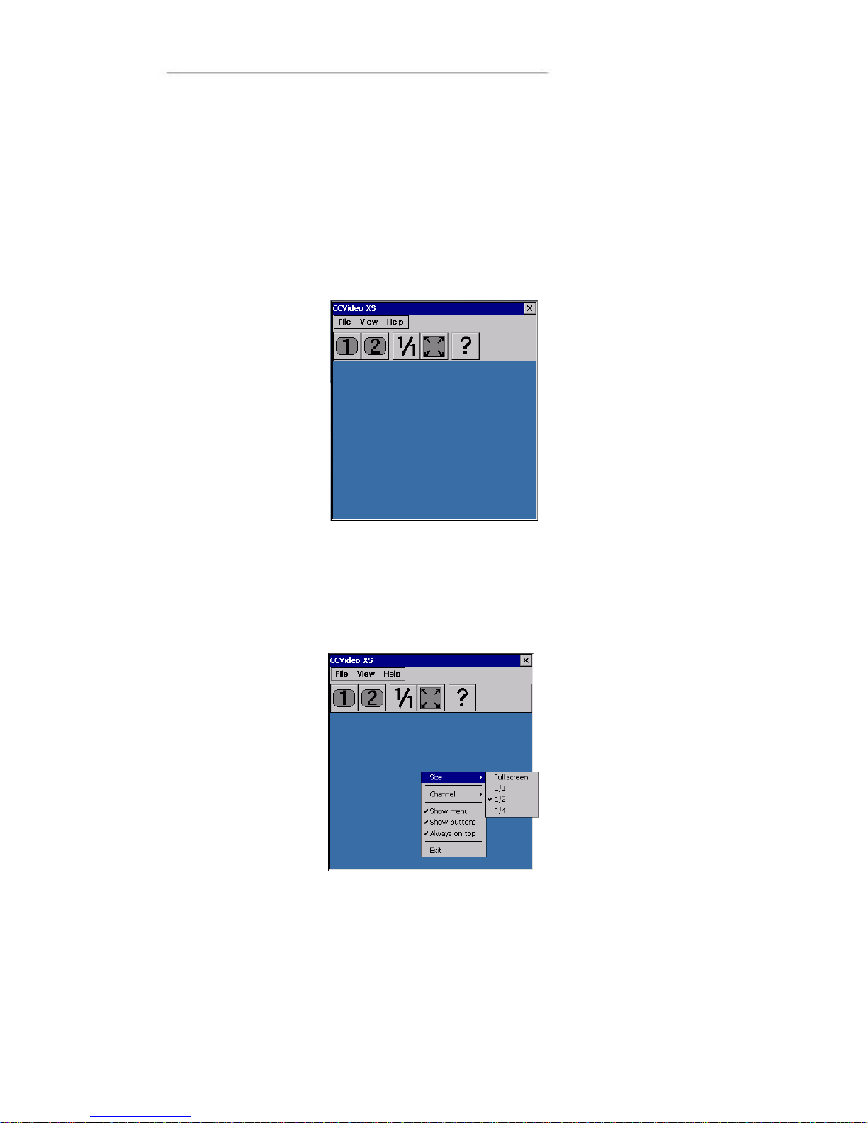
The pop up menu
When the menu and toolbar is hidden the pop up menu is used to interact with CC
Video. When using touch screen the menu is accessed by pressing and holding the
screen within the video window. If a mouse is attached to the computer the menu can
also be accessed by right clicking the mouse within the video window.
Page 37
User Manual and Reference Handbook for the CC Pilot ™ XS
37
Selecting video channel
To select which camera channel to display, press the desired channel button or select
the desired channel from the view menu.
Changing video display size
The size of the video window is changed by selecting from the predefined sizes using
the pop up menu or the view menu. The size can also be changed to any size by
dragging the window border.
Hiding toolbars and buttons
To hide the toolbar and menus and provide maximum space for the video feed,
uncheck the show menu and show buttons alternatives from the view menu. Use the
pop-up menu and check respective alternative to get the menu and toolbar back.
Changing camera settings
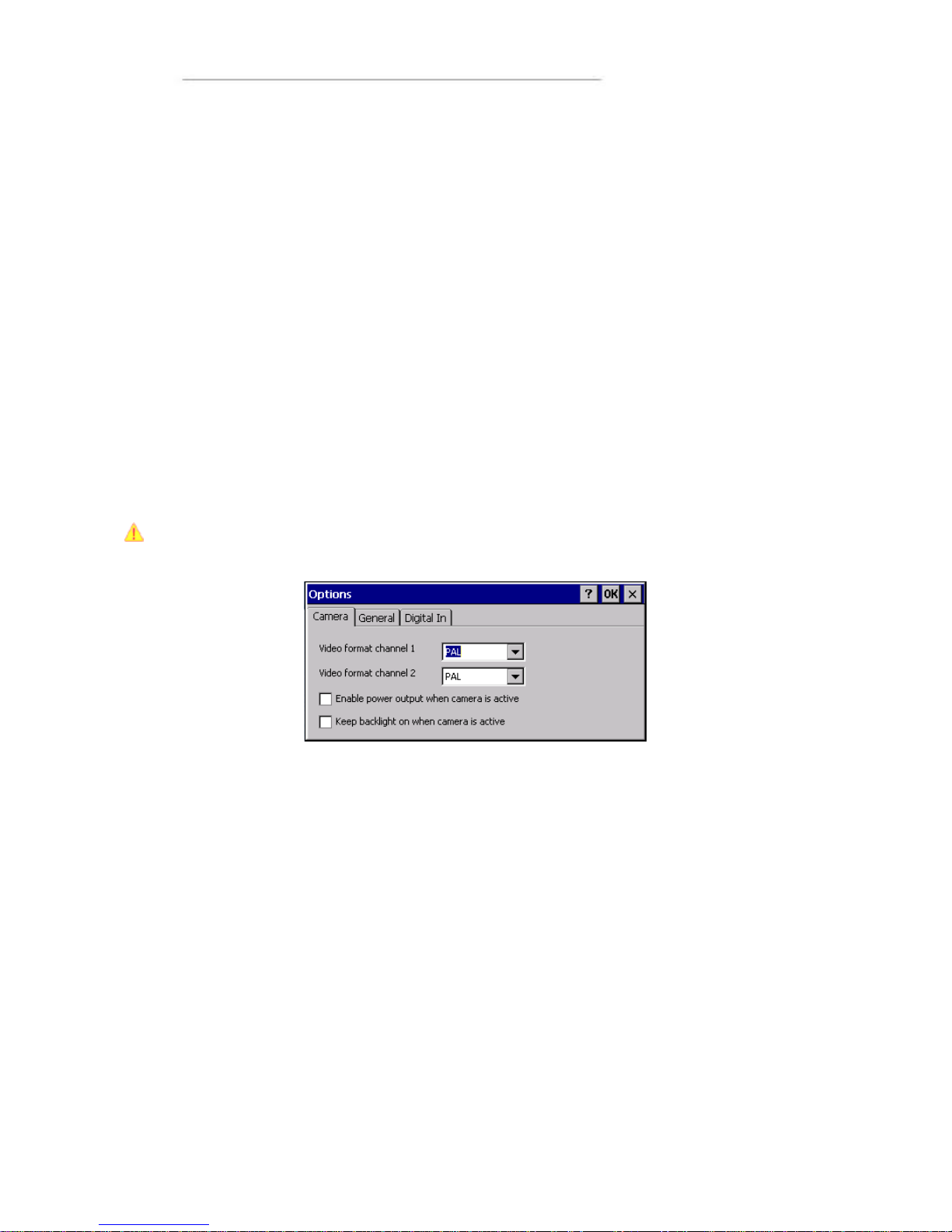
CC Pilot™ XS supports PAL and NTSC cameras. Select the format according to your
camera by accessing the options dialog from the view menu of CC Video. The format
can be set for each camera channel.
The cameras can be powered directly from CC Pilot™ XS by enabling the 12 V output
power within the camera connector.
Using the camera power output may increase the unit temperature. Also note that the
signal from the 12V power out is not filtered.
Using digital in to control video display
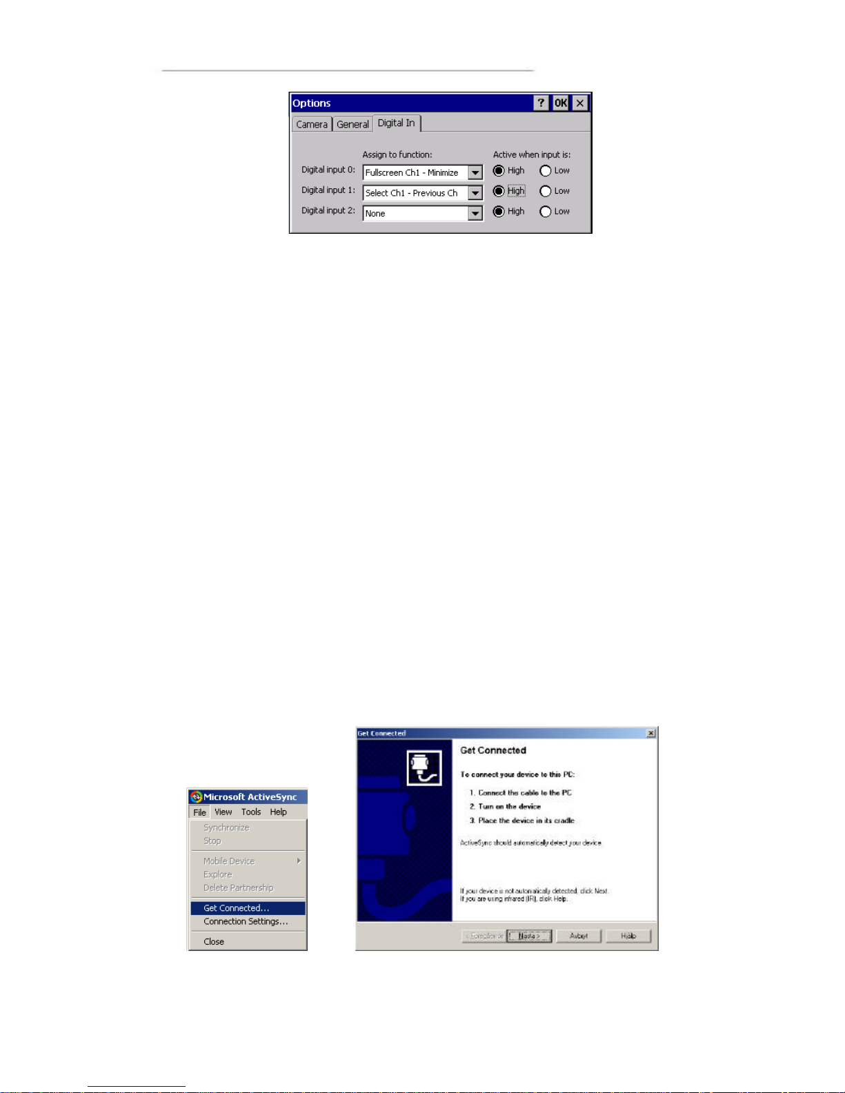
The video application can be controlled using the digital input signals optionally
available in the X9 connector of CC Pilot™ XS. The behaviour of CC Video when these
signals are changed is controlled from the Digital In settings, accessed from CC Video
by selecting options from the View menu and in the options dialog selecting Digital In.
Select the desired behaviour from the list of functions then select if this should be
activated when the signal goes high or low.
For example, one digital input can be connected to go high when a vehicle starts to
reverse. By using the function Full screen Ch1 – Minimize the video display will show
up in full screen when the vehicle starts to reverse and when finished the video window
will go back to minimized mode.
Page 38
User Manual and Reference Handbook for the CC Pilot ™ XS
38
CC Video can also be controlled from external application using a function interface.
For more information about interaction with CC Video please contact your dealer.
Microsoft ActiveSync
Microsoft ActiveSync is a desktop computer tool for Windows used to synchronise
information between the desktop computer and CC Pilot™ XS. Some third party
application also requires to be installed using ActiveSync.
Connection
There are two alternative ways to connect a computer. Either though the COM port or
through a network connection via Ethe rnet. Connecting via Ethernet gives the fastest
communication but requires that the unit first establishes a partnership, which must be
done though a COM co nnection. To connect the CC Pilot™ XS via the COM port use a
null modem cable.
Note that from version 4.0 of ActiveSync the possibility to synchronise using Ethernet
has been limited. To be able to use Ethernet as communication media Active Sync 3.8
should be used.
Establishing a Relationship
The PC connected to your CC Pilot™ XS must run Microsoft Windows and have
Microsoft A ctiveSync installed. If ActiveSync is not installed on the PC, ActiveSync can
be installed from the accompanying CD or downloaded from Microsoft’s homepage.
To be able to synchronise the CC pilot™ XS with the PC, a partnership must be
established between them. A guide takes you through the necessary steps on the PC.
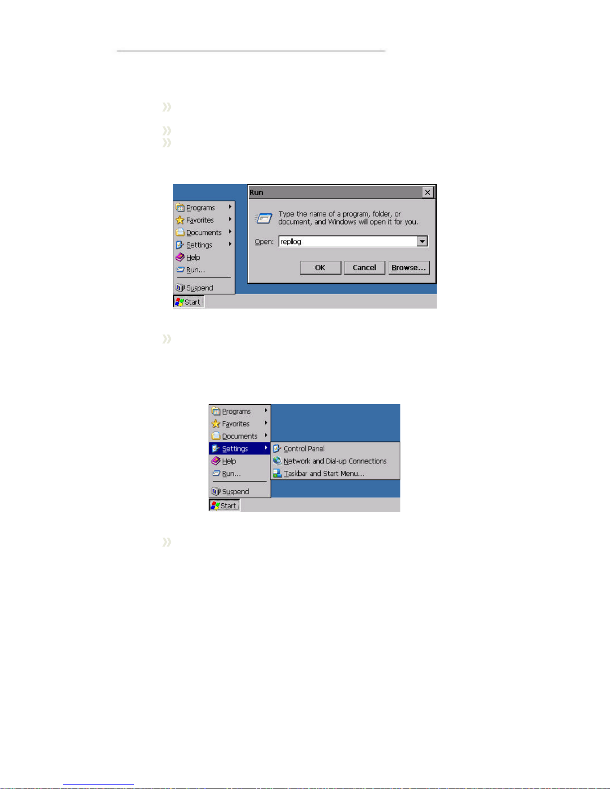
The guide starts automatically when you install Microsoft ActiveSync, it can also be
started manually by starting Microsoft ActiveSync and, in the File menu, chose Get
connected.
Page 39
User Manual and Reference Handbook for the CC Pilot ™ XS
39
When the dialogue Get Connected is shown, the following steps must be carried out so
that a connection can be established with the CC Pilot™ XS:
Ensure that the CC Pilot™ XS is connected via a null modem cable to a
PC.
Start the CC Pilot™ XS (if it is not already started)
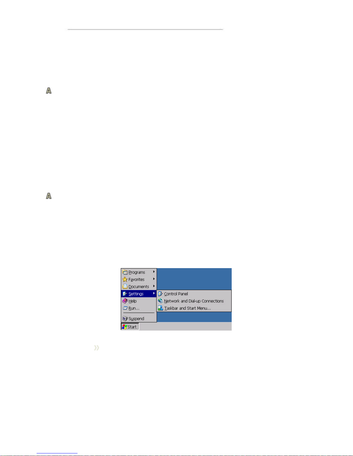
Start the program repllog on the CC Pilot™ XS. This is done via the Start
menu. Click on Run and type repllog in the wi ndow shown and then press
OK.
Now press Next in the Get Connected window on the PC. It is important
that not too long of time has passed after you pressed OK on the CC
Pilot™ XS in the previous step until you press Next in this stage. If
possible, it is recommended that that these buttons are pressed
simultaneously.
If the CC Pilot™ XS connects with the PC, there will appear a question on
the PC about establishing a partnership. Follow the directions on the
screen to establish a partnership.
To use the faster network connection, type repllog /remote in the Run window and
chose Ethernet in ActiveSync on the PC.
Transfer of Files between the PC and CC Pilot™ XS
When a connection is established between the PC and the CC Pilot™ XS , files can
easily be transfer between them. Start the Explorer file browser on the PC and select
Mobile Device to access the file system on the CC Pilot™ XS.
Page 40
User Manual and Reference Handbook for the CC Pilot ™ XS
40
Program installation
Different Windows CE programs have different requirements on how they shall be
installed. The most common is either that they are installed directly on the CC Pilot™
XS or via Microsoft ActiveSync. Consult the instructions for the program you are
installing to learn exactly how the program is installed.
Connect to the GPS receiver
The connection to the internal GPS receiver operates in the same way as with an
external GPS, which connects on the external COM port. The internal GPS receiver is
connected to an internal COM port, COM 2. The default setting for the baud rate is
4800 baud and position information is sent according to the NMEA standard.
In order to get a signal from the GPS receiver, an antenna must also be connected. For
more information regarding antenna connection please se the Installation chapter.
Occasionally, depending on the time of day and visibility against the sky, there can be
problems with the signal reception from GPS satellites and the receiver then needs
time to position it self. One may therefore need to wait several minutes before position
information can be obtained.
The GPS receiver in itself gives only position information. So, a GIS software is still
needed which interprets the signal, such as a map program.
Creating a dial -up connection with the GSM/GPRS modem
To create a remote connection via the internal GSM/GPRS modem, an antenna must
be mounted to the GSM/GPRS connection on the CC Pilot™ XS. Besides that, a SIMCard must be installed. See the Installation chapter for information on the SIM card and
antenna.
Setting up the connection
The Windows CE settings for creating a dial -up connection are found under network
connections. Network Connections is opened by pressing the Start button, choosing
Settings and then Network and Dial-up Conne ctions.
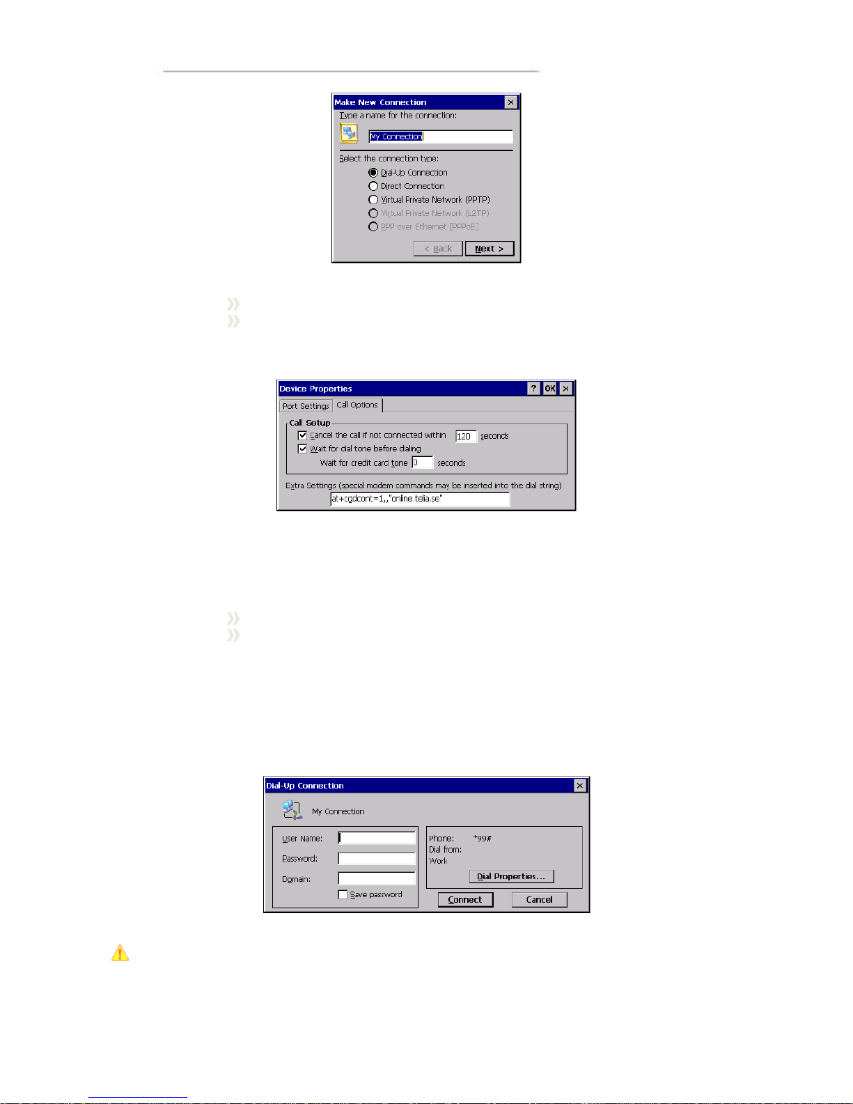
Open Make New Connection and give a name for the connection in the
dialogue which opens. Press Next.
Page 41
User Manual and Reference Handbook for the CC Pilot ™ XS
41
Chose the internal GSM/GPRS modem on COM3.
Depending on the connection, an extra AT -command may be needed..
This is done under Configure. Chose the tab Call Options in the dialogue
which opens and type in the AT-command under Extra Settings.
The contents of the AT-command vary depending on modem type and cellular network
provider. In the CC Pilot™ XS there is a Siemens AC45 modem. Contact your cellular
network provider for information on issuing the right AT-command.
Press Next.
Type in the telephone number which you would like to call and press
Finish.
Establish a connection
The connection that was created above can now be found under Network and Dial-up
Connections. To establish a link, open the connection, after which a username and
password may need to be given. Then press Connect to place the call.
Note that to place a call with the modem, the SIM card must have been configured so
that no PIN code is needed.
Page 42

User Manual and Reference Handbook for the CC Pilot ™ XS
42
Depending on the cellular network provider and what type of connection is to be made,
individual settings may be necessary. Contact your provider or network administrator
for the correct settings.
Using the FTP server
CC Pilot™ XS has an in built FTP server to be used for remotely upload or download
information from the unit.
The default security settings for FTP is to allow anonymous access, which gives the
connecting entity possibilities to upload files, delete files and rename files without
authorization. Anyone can log in using the username "anonymous" and any password
to gain access.
Be aware that when connecting CC Pilot™ XS to a network the FTP server is open for
anyone to access.
Using Telnet server
You can interact remotely with CC Pilot™ XS using the built in Telnet server. The telnet
server is accessed using a Telnet application to contact the CC Pilot™ XS using
network connection.
No login is needed to logon to the unit.
Be aware that when connecting CC Pilot™ X S to a network the Telnet server is open
for anyone to access.
Page 43
User Manual and Reference Handbook for the CC Pilot ™ XS
43
CC Pilot™ XS
Specifications
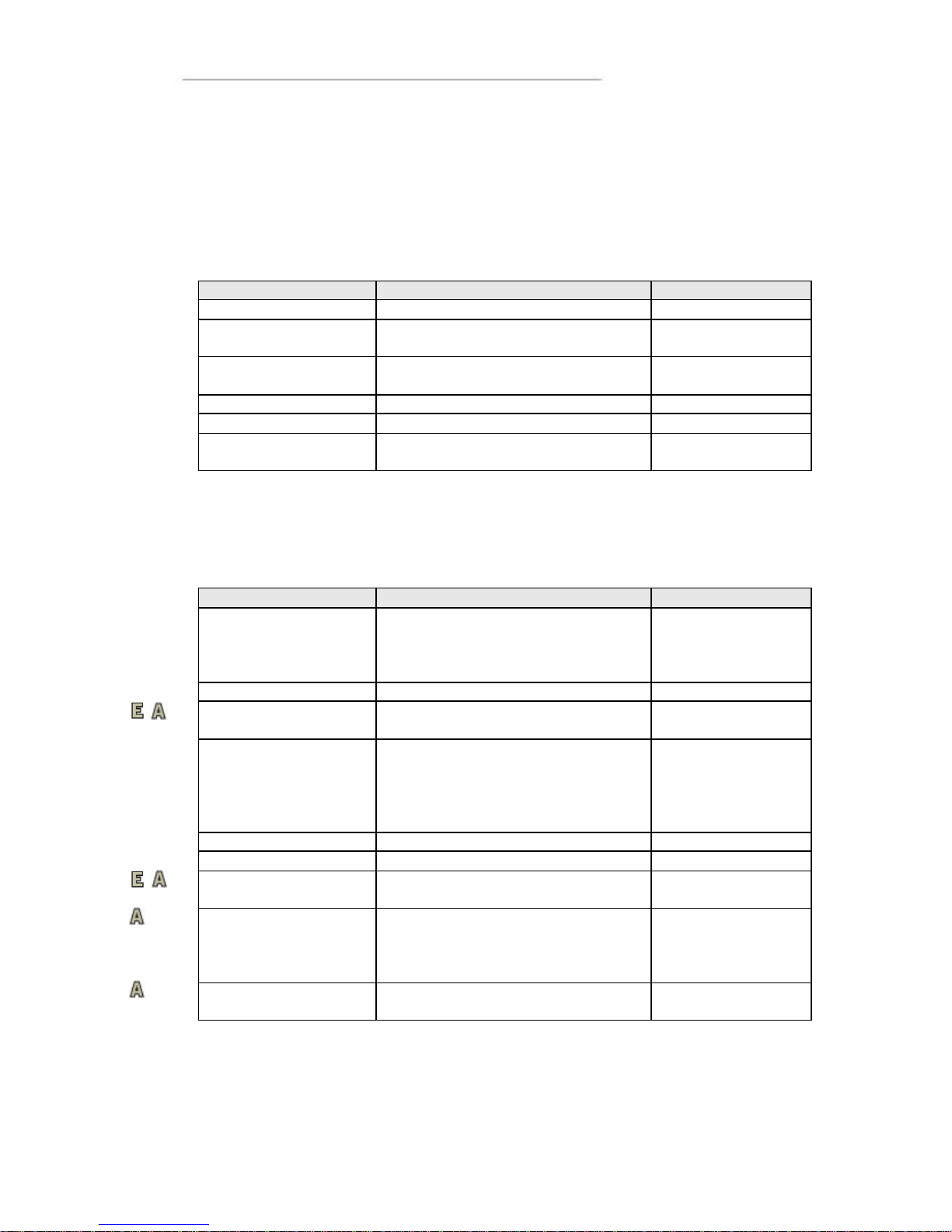
Computer Core
Core Component Description Comments
Processor Intel XScale, 533 MHz
Kernel Flash 32 MB Strata flash For operating
system
Compact Flash 1 GB For application and
user data
RAM 256 MB SDRAM
EEPROM 4+4 KB Serial
Graphic Controller Silicon Motion, 8 MB RAM, 2D/3D
acceleration
Interfaces
The composition of the unit is optional, so your CC Pilot™ XS may not be equipped
with all inte rfaces.
Interface Description Comments
CAN 2 pcs. 2.0B, ISO 11898 – 24V Controller – Intel
82527
Driver –Philips
82C251
USB 2 pcs. Ver. 2.0
Video in 2 pcs. Zoomed composite
video signal
RS232 1 pcs. <= 115 000 baud
(Limited connector
set for CC Pilot XS
Extended and
All_integrated)
Ethernet 2 pcs. 10/100 Base -T
Touch screen Resistive Touch screen 8-wire
Digital Input 3 discrete digital inputs,
Pull-up(100K, 3.3V)
Option – replaces
RS232
GPS Internal via serial connection, COM 2 12 channel receiver
-152 dBm sensitivity
NMEA and iTalk
3-m (CEP) accuracy
GSM/GPRS modem Internal via serial connection, COM 3 Siemens AC45
module
Page 44
User Manual and Reference Handbook for the CC Pilot ™ XS
44
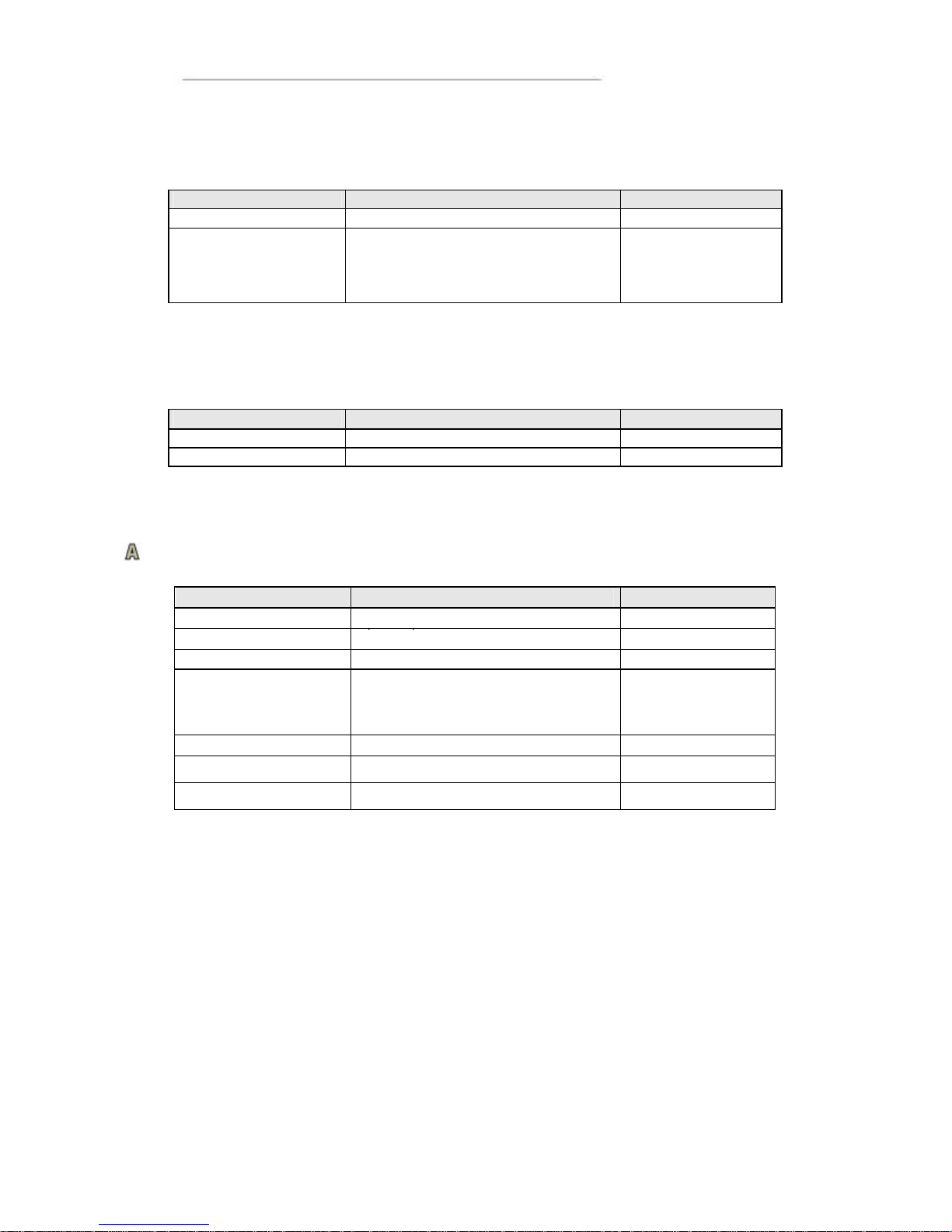
Power Supply
Power Supply Description Comments
Supply Voltage 10 to 36 V
Power Consumption Max 1A at 24 V With10.4” displays.
Varies depending
on background
lighting.
Display
Display Description Comments
6,5” VGA Colour, 640x480, 320 cd/mm* Aspect Ratio 4:3
10,4” SVGA Colour, 800x600, 320 cd/mm* Aspect Ratio 4:3
*
Light intensity can be regulated in 32 steps.
GPS
GPS
Description
Comments
Type of receiver
L1 frequency, C/A
-
code, 12
- Max update fr
e
quency
4 Hz
1 Hz default
Accuracy (SA off)
Position 3m CEP (see
1
)
Time for position
information(typical)
Cold start 35 sec (typical)
Warm start 38 sec (typical)
Fast start <8 sec (typical)
Sensitivity
-152 dBm (tracking)
Dynamic
< 4g
GPS antenna voltage
3.3 V DC
SMA connector
1
CEP = Circular Error Probability. Means that the given radius of a horizontal
circle, ce ntred at the antenna’s exact position has a 50% probability of being hit.
Page 45

User Manual and Reference Handbook for the CC Pilot ™ XS
45
GSM/GPRS
GSM/GPRS Description Comments
Frequency Band Dual-band EGSM 900, GSM1800
Broadcast strength Class 4 (2W) with EGSM900
Class 1 (1W) with GSM1800
GPRS GPRS multi-slot class 8
GPRS mobile station class B
DATA GPRS max download speed: 85.6
kbps
GPRS upload speed: max. 21.4
kbps
CSD transfer speed: 2.4, 4.8, 9.6,
14.4 kbps, V.110
SMS MO, CB, Text and PDU
CSD and GPRS
can be used for
SMS.
FAX Group 3 class 1, class 2
SIM card interface 3V SIM card
Bluetooth
Bluetooth Description Comments
Bluetooth Class 1
Range Up to 100 m
Version 2.0 compliant
Page 46

User Manual and Reference Handbook for the CC Pilot ™ XS
46
Environmental Tolerance
Environmental Test Standard Comments
Vibration IEC 60068-2-64 0,01 g2/Hz 5-200 Hz
1,39g (RMS) 1h
Shock IEC 60068-2-27
5 g/30 ms ±3x3
Dry Heat EN 60068-2-2 Bd Operating: +65°C, 24h
Storage: +70°C, 24h
Damp Heat EN 60068-2-30 Db
Operation: +25°C / +55
>93% RH 2*24h
Cold EN 60068 -2-1 Ad Operating: -40°C, 24h
Storage: -40°C, 24h
Enclosure EN 60529 IP67
EMC Directive 2004/108/EC
EN 61000 -6-2:2001
EN 61000 -6-4:2001
EMC Immunity,
Transient
EN 610 00-4-4 (Burst)
EN 61000 -4-5 (Surge)
+/- 2 kV
+/- 2 kV
EMC Immunity, ESD EN 61000 -4-2 8 kV air, 4 kV contact
EMC Immunity, RF EN 61000-4-3
EN 61000 -4-6
20 V/m, 80 MHz to 2 GHz
15 V, 15 kHz to 80 MHz
EMC Emission EN 55022 Class A
Measured from10 m
Radiated:
30 to 230 MHz 40 dBµV/m
230 MHz to1 GHz 47 dBµV/m
Conducted:
9 kHz to150 kHz 103-83 dBµV
150 kHz to 500 kHz 79 dBµV
500 kHz to 30 MHz 73 dBµV
Page 47
User Manual and Reference Handbook for the CC Pilot ™ XS
47
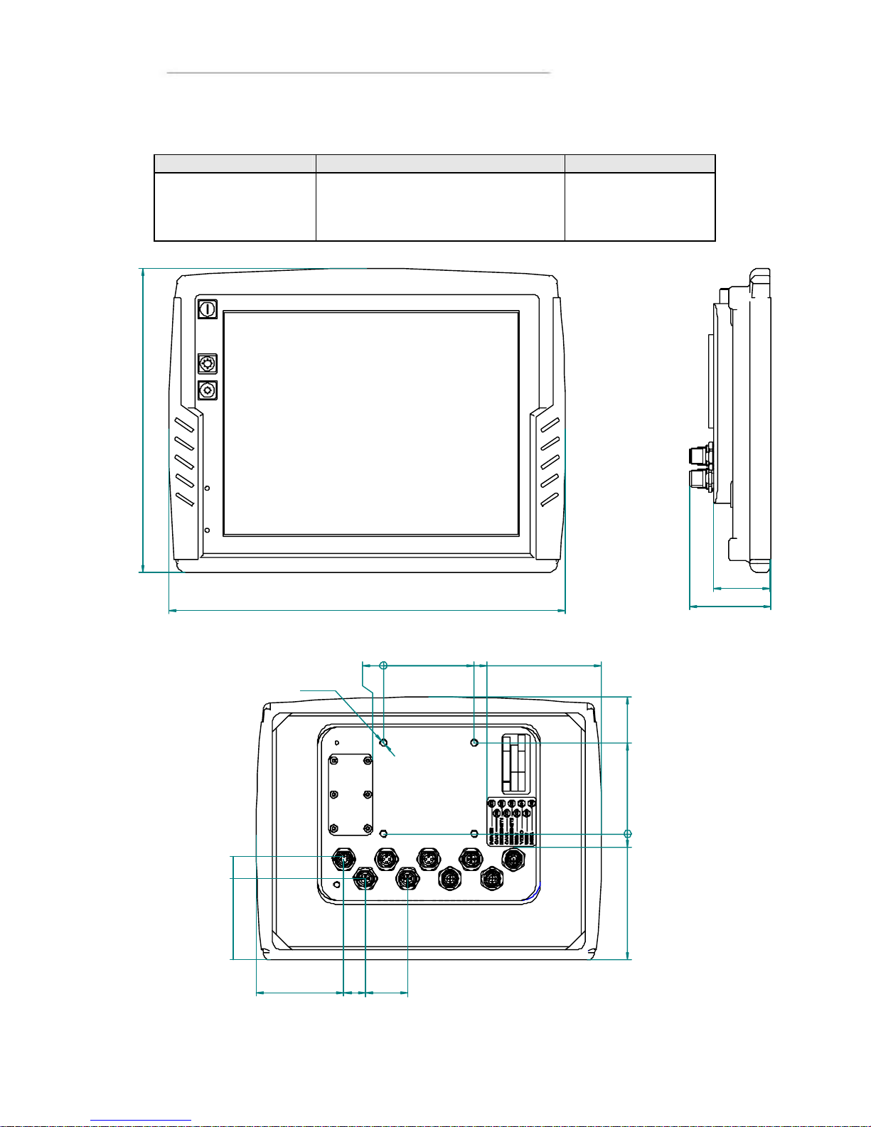
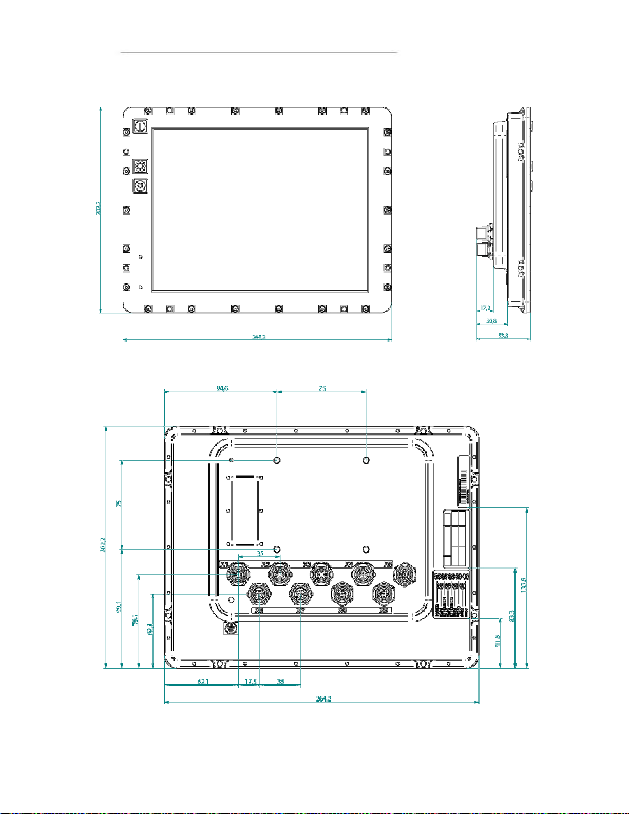
Weight and Dimensions
10.4” Description Comments
Enclosure size
Display size
Weight
285,5 x 217 x 58,4 mm (W x H x D)
210,6 x 159 x 53,8 mm (W x H x D)
ca 1.7kg
Depending on
configuration
285,5
217
58,4
40,2
18,5
72,8 17,5 35(7x)
M6 (4x)
09±
0,875180
0 75 113104
86
11
Page 48
User Manual and Reference Handbook for the CC Pilot ™ XS
48
Page 49
User Manual and Reference Handbook for the CC Pilot ™ XS
49
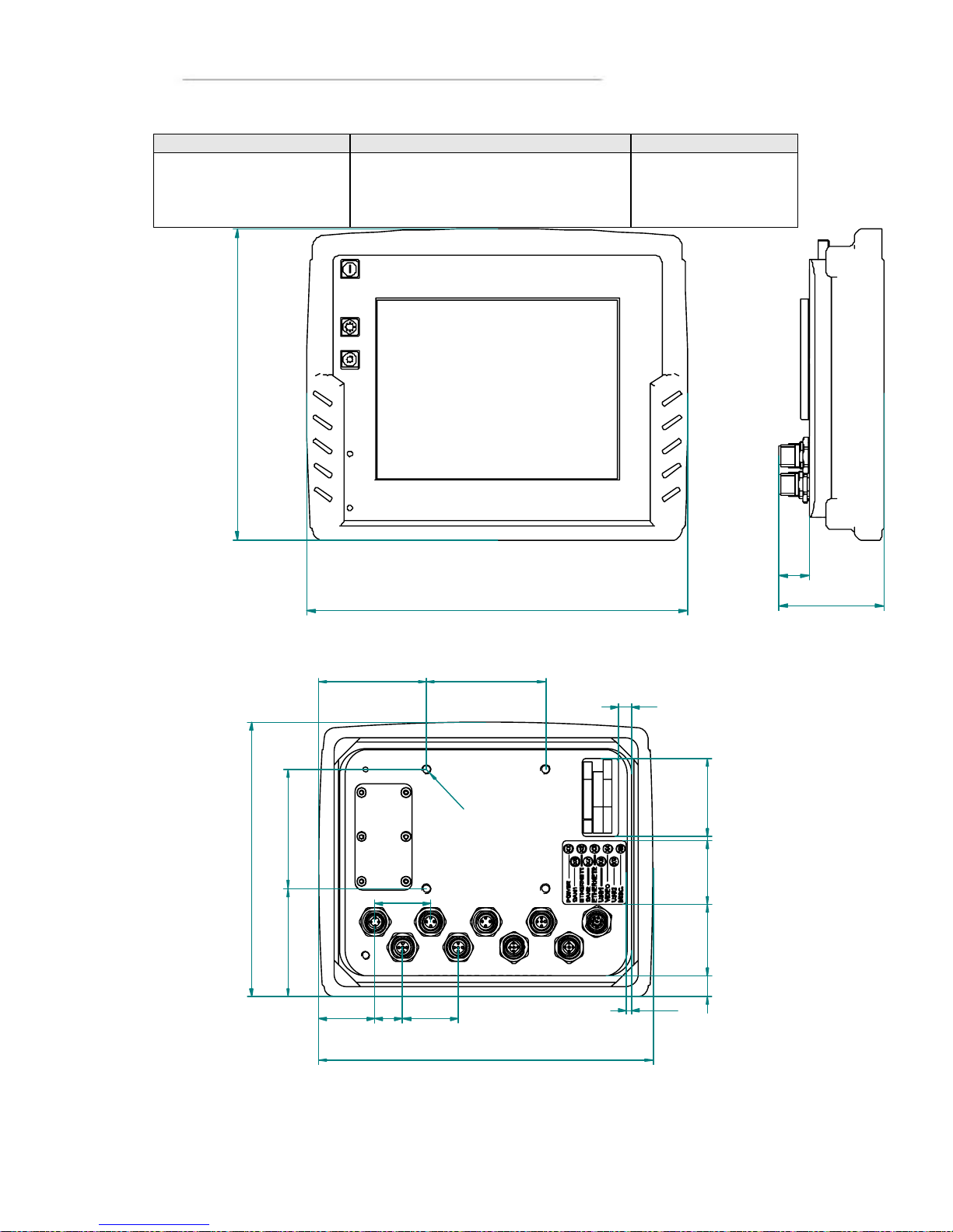
6.5” Description Comments
Enclosure size
Display size
Weight
210.8 x 172.9 x 58.4 mm (W x H x D)
198 x 163 x 53.8 mm (W x H x D)
ca 1.3 kg
Depending on
configuration
210,77
58,3
172,87
17,2
8,5
3,5
210,78
172,87
67,89
75
13 45 40 3 49
68 75
35,39 17,5 35
35
R
3
Page 50
User Manual and Reference Handbook for the CC Pilot ™ XS
50
Page 51

User Manual and Reference Handbook for the CC Pilot ™ XS
51
CC Pilot™ XS
Technical Support
Contact your reseller or supplier for help with possible problems with your CC Pilot™
XS. In order to get the best help, you should have your CC Pilot™ XS in front of you
and be prepared with the following information before you contact su pport.
Part number and serial number of the unit, which you find on the brand label
Date of purchase, which is found on the invoice
The conditions and circumstances under which the problem arises
Possible error messages which are shown.
Version number of the operating system, which you find via the Start menu:
go to the Control Panel and click on System.
Information regarding possible external equipment which is connected to
the CC Pilot™ XS.
Page 52

User Manual and Reference Handbook for the CC Pilot ™ XS
52
CC Pilot™ XS
Glossary
Bluetooth, is an open standard for wireless communication in the 2.4 GHz range. It is
built for low power consumption and is used to connect together units such as cell
phone, print er, keyboard, pointing instrument and computer. The range is 10 – 100 m.
bps, bits per second. This is a measurement of how fast data can be sent. Given often
as Mbps, or Mb/s (mega-bits per se cond)
CAN, Controller Area Network. A standard for bus communication to be used in control
applications in, for example, vehicles and industry.
CCP, CC Pilot™
COM, is an abbreviation for Communication Port and is usually called the serial port.
The serial port can, among other things, be used to connect additional equipment
(modem, GPS, etc.) to a PC.
ELFA, an electronic component distributor in northern Europe. For more information
see the chapter References.
Ethernet, computer networking technology for local area networks (LANs). The name
comes from the physical concept of ether. Ethernet is mostly standardized as IEEEs
802.3 and is the most widespread LAN technology.
GPRS, General Packet Radio Service. GPRS is a standard, accepted by the European
Standardisation Organisation ETSI, for packet data in GSM and 3G-networks. GPRS
has also been adapted for the American cellular telephone standard, TDMA.
GIS, Geographic Information System. Is a general term for programs or syst ems which
contain geographical information such as maps.
GPS, Global Positioning System. System for global positioning.
GSM, Global System for Mobile Communications. A system for mobile telephone
communication. There are three different frequency ranges which GSM uses. In
today’s GSM net data is sent in the same way as normal speech information, which
limits the data communication rates. For higher data communication rates additional
technology are added, such as GPRS.
The Cont rol Panel, is a program which accompanies your Windows operating system.
It is easiest to find by going in through the Start Menu.
LAN, Local Area Network. LAN often concerns the Ethernet standard which is used in
local networks.
Notification Area , This is an area which, in a Windows environment, is often found
lowest down to the right on the desktop, i.e. beside the clock.
Mbps, Mega bits per second. Mbps is a measurement of how fast data can be sent.
Page 53

User Manual and Reference Handbook for the CC Pilot ™ XS
53
NC, Not Connected. The socket, or a pin in the socket, is without an internal
connection and can not be used.
NMEA-0183, Protocol for GPS communication from the National Marine Electronics
Association, which was originally developed for marine use but is now an accepted de
facto standard for GPS communication in many different regions. See the chapter
References for the link to NMEA’s home page.
SIM, Subscriber Identification Module
TFT, Thin Film Transistor. A method for manufacturing flat-screens displays.
USB, Universal Serial Bus. A standard which has replaced serial and parallel ports on
PC units with a faster, more uniform standard. Many different devices can be attached
to the USB port, such as a keyboard, mouse, camera and memory, to name only a few
examples.
The Explorer, the window in your operating system where you can search through
folders and files, etc.
WLAN, stands for wireless LAN, wireless local area network also called Wi-Fi. WLAN
is a wireless local area network that uses radio waves to communicate with the mobile
device. The range is limited around 100 m, but is highly dependent on surrounding
factors. The standard is called IEEE 802.11 and exists in several versions (a, b, g)
where the speed, tangling from 2-108 Mbit is the most significant difference.
Intel XScale® A processor technology which draws low current, gives high
performance and is well-suited as an embedded processor in small units.
Page 54

User Manual and Reference Handbook for the CC Pilot ™ XS
54
CC Pilot™ XS
References
http://www.cc-systems.com
http://www.ELFA.se/
http://www.nmea.org/pub/0183/
http://www.hardwarebook.net/
Trade Mark, etc.
© 2008 CC Systems AB
All trademarks sighted in this document are the property of their respective owners.
CC Pilot is a trademark which is the property of CC Systems AB.
Intel XScale is a registered trademark which is the property of Intel Corporation in the
USA and/or other countries. Linux is a registered trademark of Linus Torvalds.
Microsoft and Wi ndows are registered trademarks which belong to Microsoft
Corporation in the USA and/or other countries.
CC Systems AB is not responsible for editing errors, technical errors or for material
which has been omitted in this document. CC Systems is not responsible for
unintentional damage or for damage which occurs as a result of supplying, handling or
using of this material. The information in this handbook is supplied without any
guarantees and can change without prior notification.
Page 55

User Manual and Reference Handbook for the CC Pilot ™ XS
55
CC Pilot™ XS
Index
A
Accuracy............................................................44
ActiveSync.........................................................38
Adapter cables..................................................15
ARM processors...............................................27
AT-command .................................................... 41
Audio ............................................................13, 15
B
Bluetooth...........................................................52
bps......................................................................52
Brightness.........................................................35
Broadcast strength...........................................45
C
Calibration of Touchscreen.............................10
Camera connection..........................................13
CAN..............................................................12, 52
CAN....................................................................43
CAN1..................................................................15
CAN2..................................................................15
CANopen.....................................................12, 17
CC Video...........................................................36
CE.......................................................................27
Cleaning................................................................5
Clock .................................................................. 28
Cold....................................................................46
Colour-coding of cable....................................26
COM...............................................13, 15, 18, 52
Communications Port......................................18
Compact flash...................................................29
Composite video ...............................................16
Composite Video..............................................13
Computer Core.................................................43
Configuration of CC Pilot XS.............................8
Connect to GPS ...............................................40
Connection to the GSM/GPRS modem........40
Connectors........................................................15
Contact Support...............................................51
Cooling of the CC Pi lot™ XS ......................... 21
D
DHCP.................................................................32
Dial-up Connection..........................................40
Digital In.............................................................15
Digital Input.......................................................43
Digital Inputs .....................................................13
Display ............................................................... 44
Display size 10.4..............................................47
Display Size 6.5................................................49
Dynamic.............................................................44
E
ELFA..................................................................52
EMC ...................................................................46
Enclosure...........................................................46
Enclosure size 6.5............................................49
Enclosure size, 10.4 ........................................47
Environmental Test ..........................................46
Environmental Tolerance............................5, 46
Ethernet.......................................................12, 43
Ethernet1...........................................................15
Ethernet2...........................................................15
F
fastening holes .................................................22
FAX.....................................................................45
Flash Memory...................................................43
Frequency band...............................................45
G
Get Connected.................................................38
Getting started with Windows CE..................27
GIS ...............................................................40, 52
Glossary.............................................................52
GPRS...........................................................13, 52
GPS................................................13, 43, 44, 52
GPS antenna voltage ...................................... 44
GPS connection...............................................40
GPS receiver.....................................................40
GPS-receiver....................................................44
Graphic Controller............................................43
GSM.............................................................13, 52
GSM/GPRS.......................................................43
GSM/GPRS.......................................................14
GSM/GPRS.......................................................45
GSM/GPRS connection..................................40
H
Hard disc...........................................................12
Heat....................................................................46
I
Identification.........................................................4
Input lange selection ........................................28
Input panel.........................................................28
Input Panel........................................................29
Inputs.................................................................15
Installation of CC Pilot™ XS...........................21
Installation of software........................................8
Installing the Unit..............................................21
Interfaces...........................................................43
Internal GPS-unit..............................................13
Internet Explorer...............................................28
K
Keyboard ........................................................... 29
L
Label......................................................................4
Page 56

User Manual and Reference Handbook for the CC Pilot ™ XS
56
LAN.....................................................................52
Light Emitting Diode.........................................10
Linux...................................................................27
M
Maintenance ........................................................5
Mbps...................................................................52
Memory..............................................................12
Minimise all windows.......................................28
MISC ..................................................................15
Modem...............................................................13
Module description ...........................................12
My Computer....................................................28
N
NC.......................................................................53
Network Status .................................................28
NMEA.................................................................40
NMEA-0183 standard......................................13
NMEA-0183 Standard.....................................53
Notification Area...............................................52
NTSC...........................................................13, 16
null modem cable.............................................38
O
Operating System ............................................27
Outputs..............................................................15
Overview of the CC Pilot™ XS .........................6
P
PAL ...............................................................13, 16
Performance ..................................................... 43
PIN code............................................................41
Pins.....................................................................15
Placement of the CC Pilot™ XS ....................21
Ports...................................................................15
Power Consumption........................................44
Power states .....................................................34
Power Supply ....................................................44
Power Supply Cable........................................26
Power Supply Connector................................15
processor...........................................................43
R
RAM memory....................................................43
Rear View Camera...........................................13
References........................................................54
repllog ................................................................ 39
Reset the unit....................................................11
RS232..........................................................18, 43
S
Sensitivity..........................................................44
Settings..............................................................32
Setting-up CC Pilot XS.......................................8
Shock ................................................................. 46
Shutting Down the CC Pilot™ XS .................10
SIM.....................................................................53
SMS....................................................................45
Software.............................................................27
Software installation............................................8
Specifications....................................................43
Start button........................................................28
Status for power supply ...................................28
Status Indic ation...............................................10
Storage .............................................................. 12
Supply Voltage.................................................44
Support .............................................................. 51
System memory...............................................29
T
Technical Support............................................51
Test Standards ....................................................5
TFT.....................................................................53
The Control Panel............................................52
The Explorer...............................................29, 53
The Network ......................................................29
thread depth......................................................21
thread locker.....................................................22
torque...........................................................21, 22
Touchscreen...............................................10, 43
Trade Mark........................................................54
Traffic safety.....................................................21
Turning off the CC Pilot™ XS ........................10
U
USB .......................................................13, 15, 53
USB .................................................................... 43
USB host mode................................................19
Using the CC Pilot XS .....................................27
V,W
Warranty............................................................21
Weight 10.4.......................................................47
Weight 6.5.........................................................49
Weight and Dimensions..................................47
Welding.................................................................4
Vibration.............................................................46
Video ............................................................15, 43
Video camera ....................................................13
Video Controller ................................................43
Video input........................................................15
Windows CE.....................................................27
WLAN.................................................................53
Volume Control .................................................28
X
XS settings........................................................32
XScale................................................................53
Xscale processors............................................27
Page 57

User Manual and Reference Handbook for the CC Pilot ™ XS
57
Sales contact
pro
ductsales@cc
-
systems.com
Phone
+46 (0)271 193 80
Address CC Systems AB Fax +46 (0)271 193 89
Box 83 Web www.cc-systems.com
SE -822 22 Alfta General contact [email protected]
Sweden
Manufacturer contact information
 Loading...