


Test Equipment Depot - 800.517.8431 - 5 Commonwealth Ave, Woburn MA 01801 - TestEquipmentDepot.com
WattNode® Modbus
Installation and Operation Manual
WattNode Modbus
Models
● WNC-3Y-208-MB
● WNC-3Y-400-MB
● WNC-3Y-480-MB
● WNC-3Y-600-MB
● WNC-3D-240-MB
● WNC-3D-400-MB
● WNC-3D-480-MB
WattNode Revenue for
Modbus Models
● RWNC-3Y-208-MB
● RWNC-3Y-400-MB
● RWNC-3Y-480-MB
● RWNC-3Y-600-MB
● RWNC-3D-240-MB
● RWNC-3D-400-MB
● RWNC-3D-480-MB
Rev 1.18 c
(M7)

This equipment has been tested and complies with the limits for a Class B digital device, pursuant to part 15 of the FCC Rules. Operation is subject to the following two conditions: (1) This
device may not cause harmful interference, and (2) this device must accept any interference
received, including interference that may cause undesired operation.
The FCC limits are designed to provide reasonable protection against harmful interference in a
residential installation. This equipment generates, uses and can radiate radio frequency energy
and, if not installed and used in accordance with the instructions, may cause harmful interference to radio communications. However, there is no guarantee that interference will not occur in
a particular installation. If this equipment does cause harmful interference to radio or television
reception, which can be determined by turning the equipment off and on, the user is encouraged
to try to correct the interference by one or more of the following measures:
● Reorient or relocate the receiving antenna.
● Increase the separation between the equipment and receiver.
● Connect the equipment into an outlet on a circuit different from that to which the receiver is
connected.
● Consult the dealer or an experienced radio/TV technician to help.
2

Contents
Overview ................................................................................................................................5
Measurements ................................................................................................................................ 5
Communication ............................................................................................................................... 5
Diagnostic LEDs .............................................................................................................................. 5
Options ........................................................................................................................................... 5
Current Transformers ....................................................................................................................... 6
Additional Literature ......................................................................................................................... 6
Front Label ...................................................................................................................................... 7
Installation .............................................................................................................................9
Precautions ..................................................................................................................................... 9
Electrical Service Types ..................................................................................................................10
Single-Phase Two-Wire with Neutral .........................................................................................10
Single-Phase Three-Wire (Mid-Point Neutral) ............................................................................11
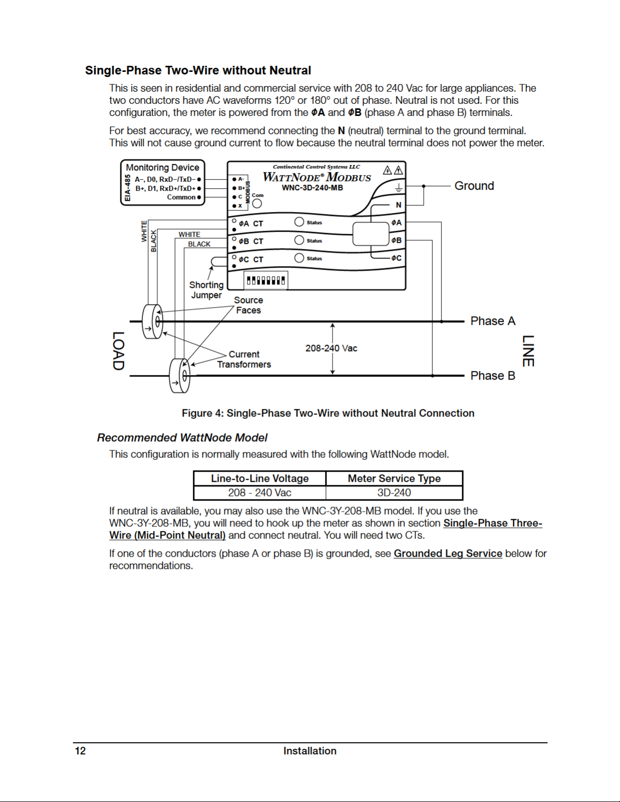
Single-Phase Two-Wire without Neutral ....................................................................................12
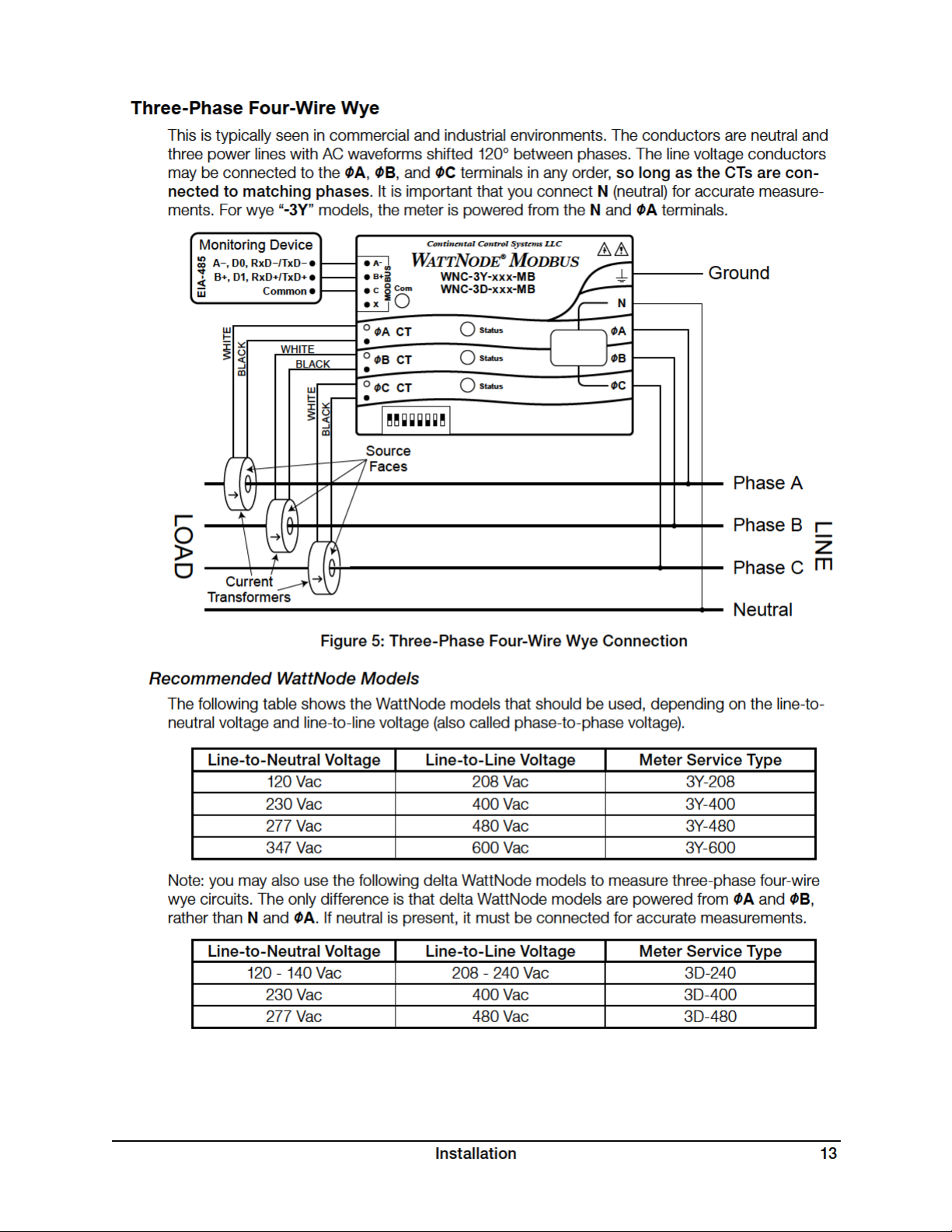
Three-Phase Four-Wire Wye
Three-Phase Three-Wire Delta Without Neutral .........................................................................14
Three-Phase Four-Wire Delta (Wild Leg) ...................................................................................14
Grounded Leg Service .............................................................................................................14
Mounting ........................................................................................................................................15
Selecting Current Transformers ......................................................................................................16
Connecting Current Transformers ...................................................................................................17
Circuit Protection ............................................................................................................................18
Connecting Voltage Terminals .........................................................................................................19
Setting the Modbus Address ..........................................................................................................19
Baud Rate ............................................................................................................................... 20
Connecting Modbus Outputs ......................................................................................................... 20
Planning the Modbus Network ................................................................................................ 20
Installation Summary ..................................................................................................................... 22
Wiring ..................................................................................................................................... 22
Installation LED Diagnostics ........................................................................................................... 23
Other Fixed Pattern ................................................................................................................. 25
Measurement Troubleshooting ....................................................................................................... 25
Modbus Communication Diagnostics ............................................................................................ 28
Operating Instructions ......................................................................................................... 30
Quick Start .................................................................................................................................... 30
WattNode Basic Configuration ................................................................................................ 30
Verify Operation ...................................................................................................................... 30
Measurement Overview ............................................................................................................31
Modbus Communication ................................................................................................................31
Modbus Functions ...................................................................................................................31
Modbus Register Lists ................................................................................................................... 32
Modbus Register Addressing .................................................................................................. 32
Report Slave ID ....................................................................................................................... 32
Floating Point and Integer Registers ........................................................................................ 33
Reading and Writing 32 Bit Registers ...................................................................................... 33
Basic Register List - Floating Point .......................................................................................... 34
Basic Register List - Integer ..................................................................................................... 34
Advanced Register List - Floating Point ................................................................................... 35
.....................................................................................................13
Contents 3

Advanced Register List - Integer .............................................................................................. 36
Configuration Register List .......................................................................................................37
Communication Register List ................................................................................................... 38
Diagnostic Register List ........................................................................................................... 38
Option Information Registers ................................................................................................... 39
Custom Register Map ............................................................................................................. 39
Basic Registers ............................................................................................................................. 40
Energy Registers ..................................................................................................................... 40
Power Registers ...................................................................................................................... 40
Voltage Registers .....................................................................................................................41
Frequency ................................................................................................................................41
Advanced Registers .......................................................................................................................41
Per-Phase Energy Registers .....................................................................................................41
Positive Energy .........................................................................................................................41
Negative Energy ...................................................................................................................... 42
Reactive Energy ...................................................................................................................... 42
Apparent Energy ..................................................................................................................... 42
Power Factor ........................................................................................................................... 42
Reactive Power ....................................................................................................................... 43
Apparent Power ...................................................................................................................... 43
Current.................................................................................................................................... 44
Demand .................................................................................................................................. 44
I/O Pin Options ........................................................................................................................ 46
Configuration Registers ................................................................................................................. 46
Demand Configuration ............................................................................................................ 48
Zeroing Registers .................................................................................................................... 49
I/O Pin Options Configuration .................................................................................................. 50
Communication Registers .............................................................................................................. 50
Diagnostic Registers .......................................................................................................................51
Error Codes ................................................................................................................................... 52
Maintenance and Repair ................................................................................................................ 54
Specifications ......................................................................................................................55
Models .......................................................................................................................................... 55
Model Options ........................................................................................................................ 55
Accuracy ................................................................................................................................. 56
Measurement ................................................................................................................................ 57
Modbus Communication ............................................................................................................... 57
Electrical ....................................................................................................................................... 58
Certifications ................................................................................................................................. 59
Environmental ................................................................................................................................ 59
Mechanical .................................................................................................................................... 59
Current Transformers ..................................................................................................................... 59
Warranty ...............................................................................................................................60
Limitation of Liability ...................................................................................................................... 60
4 Contents

Overview
Congratulations on your purchase of the WattNode® Modbus® watt/watt-hour transducer (meter).
The WattNode meter offers precision energy and power measurements in a compact pack-
age. It enables you to make power and energy measurements within existing electric service
panels avoiding the costly installation of subpanels and associated wiring. It is designed for use
in demand side management (DSM), sub-metering, and energy monitoring applications. The
WattNode meter communicates on an EIA RS-485 two-wire bus using the Modbus protocol.
Models are available for single-phase, three-phase wye, and three-phase delta configurations for
voltages from 120 VAC to 600 VAC at 50 and 60Hz.
Measurements
The WattNode Modbus meter measures the following:
● True RMS Power - Watts (Phase A, Phase B, Phase C, Sum)
● Reactive Power - VARs (Phase A, Phase B, Phase C, Sum)
● Power Factor (Phase A, Phase B, Phase C, Average)
● True RMS Energy - Watthours (Phase A, Phase B, Phase C, Sum)
● Reactive Energy - VAR-hours (Sum)
● AC Frequency
● RMS Voltage (Phase A, Phase B, Phase C)
● RMS Current (Phase A, Phase B, Phase C)
● Demand and Peak Demand
One WattNode Modbus meter can measure up to three different “single-phase two-wire with
neutral” branch circuits from the same service by separately monitoring the phase A, B, and C
values. If necessary, you can use different CTs on the different circuits.
Communication
The WattNode meter uses a half-duplex EIA RS-485 interface for communication. The standard
baud rates are 9,600 and 19,200 baud, and rates from 1,200 to 38,400 baud can be configured.
The meter uses the industry standard Modbus RTU (binary) communication protocol, allowing
up to 127 devices per RS-485 subnet. The WattNode meter can auto-detect RS-485 polarity on
properly biased networks, simplifying installation.
There are numerous low-cost RS-485 interfaces to PCs, using both USB and serial ports. There
are many PC programs and standalone devices for collecting and recording Modbus data.
Diagnostic LEDs
The meter includes three power diagnostic LEDs—one per phase. During normal operation,
these LEDs flash on and off, with the speed of flashing roughly proportional to the power on each
phase. The LEDs flash green for positive power and red for negative power. Other conditions are
signaled with different LED patterns. See Installation LED Diagnostics (p. 23) for details.
The Modbus WattNode meter includes a communication LED that lights green, yellow, or red to
diagnose the RS-485 network. See Modbus Communication Diagnostics (p. 28) for details.
Options
The WattNode Modbus meter can be ordered with several options. For more details and docu-
mentation, see article WattNode Modbus - Options on our website.
General Options
● Option CT=xxx - Pre-assign xxx as the global CtAmps value.
Overview 5

● Option CT=xxx/yyy/zzz - Pre-assign xxx to CtAmpsA, yyy to CtAmpsB, and zzz to
CtAmpsC.
Communication Options
● Option EP - Factory configure the Modbus RS-485 communications to even parity (E81).
● Option 19K - Factory configure the RS-485 communications 19,200 baud. Position 8 of the
DIP switch will be ignored.
● Option 38K - Factory configure the RS-485 communications to 38,400 baud. Position 8 of
the DIP switch will be ignored.
● Option TCP‑RTU - Configure the communications to the Modbus TCP-RTU protocol option
for use with RS-485 to Ethernet gateways (serial device adapters).
● Option AD - Factory configure the Modbus address. The DIP switch address will be ignored.
X Terminal Options
These options utilize the X (auxiliary) terminal on the MODBUS connector. Only one of these can
be ordered on any single meter.
● Option X5 - Provides 5 VDC at up to 60 milliamps between the C (common) and X (5 V)
terminals.
● Option IO - Provides a digital input (level sensing and pulse counting) or output (for load
shedding and other applications) on the X terminal.
● Option SSR - Provides a solid-state relay (contact closure) output between the X and C
terminals for load shedding and other applications.
Special Options
Contact the factory about the following special options:
● Option 232 - Provide RS-232 I/O in place of RS-485.
● Option TTL - Provide 5 V TTL UART I/O in place of RS-485.
Current Transformers
The WattNode meter uses solid-core (toroidal), split-core (opening), and bus-bar style current
transformers (CTs) with a full-scale voltage output of 0.33333 Vac. Split-core and bus-bar CTs
are easier to install without disconnecting the circuit being measured. Solid-core CTs are more
compact, generally more accurate, and less expensive, but installation requires that you discon-
nect the circuit to install the CTs.
Additional Literature
These additional documents are available on the Continental Control Systems, LLC website or
Modbus.org website.
● WattNode Modbus - Quick Install Guide
● WattNode Modbus Register List (Excel format): WNC-Modbus-Register-List-V18.xls
● Continental Control Systems, LLC website
○ http://www.ccontrolsys.com/w/WattNode_Modbus - main page.
○ http://www.ccontrolsys.com/w/Category:WattNode_Modbus - support articles.
● http://www.modbus.org/specs.php
○ Modbus Application Protocol Specification - V1.1b
○ Modbus over Serial Line - Specification & Implementation Guide - V1.0
6 Overview


Test Equipment Depot - 800.517.8431 - 5 Commonwealth Ave, Woburn MA 01801 - TestEquipmentDepot.com
Electrical Service Types
Below is a list of service types, with connections and recommended models. Note: the ground
connection improves measurement accuracy, but is not required for safety.
Electrical
Service (or Load) Types
Line-to-
Neutral (Vac)
Line-to-
Line
(Vac)
Meter
Service
Type
1 Phase 2 Wire 120V with neutral 96 – 138 n.a. 3Y-208
1 Phase 2 Wire 230V with neutral
(non-U.S.)
184 – 264
n.a. 3Y-40 0
1 Phase 2 Wire 277V with neutral 222 – 318 n.a. 3Y-48 0
1 Phase 2 Wire 208V no neutral n.a. 166 – 276 3D -240
1 Phase 2 Wire 240V no neutral n.a. 166 – 276 3D -240
1 Phase 3 Wire 120V/240V with
neutral
96 – 138 166 – 276
3Y- 208
3D -240
3 Phase 3 Wire Delta 208V no neutral n.a. 166 – 276 3D -240
3 Phase 3 Wire Delta 400V no neutral
(non-U.S.)
n.a. 320 – 460 3D-400
3 Phase 3 Wire Delta 480V no neutral n.a. 384 – 552 3D-480
3 Phase 4 Wire Wye 120V/208V with
neutral
3 Phase 4 Wire Delta 120/208/240V
with neutral
3 Phase 4 Wire Wye 230V/400V with
neutral (non-U.S.)
3 Phase 4 Wire Wye 277V/480V with
neutral
3 Phase 4 Wire Delta 240/415/480V
with neutral
3 Phase 4 Wire Wye 347V/600V with
neutral
96 – 138 166 – 276
96 – 138 166 – 276 3D-240
184 – 264 320 – 460
222 – 318 384 – 552
222 – 318 384 – 552 3D-480
278 – 399 480 – 690 3Y-60 0
3Y- 208
3D -240
3Y- 4 0 0
3D-40
3Y- 4 8 0
3D-480
Table 1 : WattNode Models
0
Meter
Powered by
N and ØA
N and ØA
N and ØA
ØA and ØB
ØA and ØB
N and ØA
ØA and ØB
ØA and ØB
ØA and ØB
ØA and ØB
N and ØA
ØA and ØB
ØA and ØB
N and ØA
ØA and ØB
N and ØA
ØA and ØB
ØA and ØB
N and ØA
Single-Phase Two-Wire with Neutral
This configuration is most often seen in homes and offices. The two conductors are neutral and
line. For these models, the meter is powered from the N and ØA terminals.
Monitoring Device
A−, D0, Rx D−/TxD −
B+, D1, RxD+ /TxD+
EIA-485
LOAD
Common
WHITE
BLACK
Shorting
Jumpers
Source
Face
Current
Transformer
Figure 2: Single-Phase Two-Wire Connection
10 Installation
Continental Control Systems LLC
A
WATTNODE®MODBUS
+
B
C
X
ØA CT
ØB CT
ØC CT
WNC-
Com
MODBUS
3Y-xxx
Status
Status
Status
-MB
ØA
ØB
ØC
Ground
N
Line
LINE
Neutral


The WattNode meter will correctly measure services with a grounded leg, but the measured voltage and power for the grounded phase will be zero and the status LED will not light for whichever
phase is grounded, because the voltage is near zero. Also, one or both of the active (nongrounded) phases may indicate low power factor because this type of service results in unusual
power factors.
For optimum accuracy with a grounded leg, you should also connect the N (neutral) terminal
on the meter to the ground terminal; this will not cause any ground current to flow because the
neutral terminal is not used to power the meter. If you have a grounded leg configuration, you can
save money by removing the CT for the grounded phase, since all the power will be measured on
the non-grounded phases. We recommend putting the grounded leg on the ØB or ØC inputs and
attaching a note to the meter indicating this configuration for future reference.
Mounting
Protect the WattNode meter from moisture, direct sunlight, high temperatures, and conductive
pollution (salt spray, metal dust, etc.) If moisture or conductive pollution may be present, use an
IP 66 or NEMA 4 rated enclosure to protect the meter. Due to its exposed screw terminals, the
meter must be installed in an electrical service panel, an enclosure, or an electrical room. The
meter may be installed in any orientation, directly to a wall of an electrical panel or junction box.
153 mm (6.02 in)
85.1 mm (3.35 in)
Ø
9.8 mm (0.386 in)
136.6 mm (5.375 in)
Ø
5.1 mm (0.200 in)
38 mm (1.50 in) High
Figure 7: WattNode Meter Dimensions
The WattNode meter has two mounting holes spaced 5.375 inches (137 mm) apart (center to
center). These mounting holes are normally obscured by the detachable screw terminals. Remove
the screw terminals by pulling outward while rocking from end to end. The meter or Figure 7
may be used as a template to mark mounting hole positions, but do not drill the holes with the
meter in the mounting position because the drill may damage the connectors and leave drill
shavings in the connectors.
You may mount the meter with the supplied #8 self-tapping sheet metal screws using 1/8
inch pilot hole (3.2 mm). Or you may use hook-and-loop fasteners. If you use screws, avoid
Installation 15

over-tightening which can crack the case. If you don’t use the supplied screws, the following
sizes should work (bold are preferred); use washers if the screws could pull through the mounting
holes
Screw Style U.S.A. UTS Sizes Metric Sizes
Pan Head or Round Head #6, #8, #10 M3.5, M4, M5
Truss Head #6, #8 M3.5, M4
Hex Washer Head (integrated washer) #6, #8 M3.5, M4
Hex Head (add washer) #6, #8, #10 M3.5, M4, M5
Table 2: Mounting Screws
Selecting Current Transformers
The rated full-scale current of the CTs should normally be chosen somewhat above the maximum
current of the circuit being measured (see Current Crest Factor below for more details). In some
cases, you might select CTs with a lower rated current to optimize accuracy at lower current
readings. Take care that the maximum allowable current for the CT can not be exceeded without
tripping a circuit breaker or fuse; see Current Transformers (p. 59).
We only offer CTs that measure AC current, not DC current. Significant DC current can saturate
the CT magnetic core, reducing the AC accuracy. Most loads only have AC current, but some rare
loads draw DC current, which can cause measurement errors. See our website for more information: http://www.ccontrolsys.com/w/DC_Current_and_Half-Wave_Rectified_Loads.
CTs can measure lower currents than they were designed for by passing the wire through the
CT more than once. For example, to measure currents up to 1 amp with a 5 amp CT, loop the
wire through the CT five times. The CT is now effectively a 1 amp CT instead of a 5 amp CT. The
effective current rating of the CT is the labeled rating divided by the number of times that the wire
passes through the CT.
If you are using the measurement phases of the WattNode (ØA, ØB, and ØC) to measure different circuits, you can use CTs with different rated current on the different phases. Instead of
setting one CtAmps value for all phases, you can use different values for each phase: CtAmpsA,
CtAmpsB, and CtAmpsC.
Current Crest Factor
The term “current crest factor” is used to describe the ratio of the peak current to the RMS current (the RMS current is the value reported by multimeters and the WattNode meter). Resistive
loads like heaters and incandescent lights have nearly sinusoidal current waveforms with a crest
factor near 1.4. Power factor corrected loads such as electronic lighting ballasts and computer
power supplies typically have a crest factor of 1.4 to 1.5. Battery chargers, VFD motor controls,
and other nonlinear loads can have current crest factors ranging from 2.0 to 3.0, and even higher.
High current crest factors are usually not an issue when metering whole building loads, but can
be a concern when metering individual loads with high current crest factors. If the peak current is
too high, the meter’s CT inputs can clip, causing inaccurate readings.
This means that when measuring loads with high current crest factors, you may want to be
conservative in selecting the CT rated current. For example, if your load draws 10 amps RMS, but
has a crest factor of 3.0, then the peak current is 30 amps. If you use a 15 amp CT, the meter will
not be able to accurately measure the 30 amp peak current. Note: this is a limitation of the meter
measurement circuitry, not the CT.
The following graph shows the maximum RMS current for accurate measurements as a function
of the current waveform crest factor. The current is shown as a percentage of CT rated current.
For example, if you have a 10 amp load with a crest factor of 2.0, the maximum CT current is
approximately 85%. Eighty-five percent of 15 amps is 12.75, which is higher than 10 amps, so
16 Installation


To connect CTs, pass the wire to be measured through the CT and connect the CT to the meter.
Always remove power before disconnecting any live wires. Put the line conductors through
the CTs as shown in the section Electrical Service Types (p. 10). You may measure generated power by treating the generator as the source.
For solid-core CTs, disconnect the line voltage conductor to install it through the CT opening.
Split-core and bus-bar CTs can be opened for installation around a wire. Different models have
different opening mechanisms, so you should familiarize yourself with the CT mechanism before
starting the installation. A nylon cable tie can be secured around the CT to prevent inadvertent
opening.
Some split-core CT models have flat mating surfaces. When installing this type of CT, make sure
that mating surfaces are clean. Any debris between the mating surfaces will increase the gap,
decreasing accuracy.
Connect the CT lead wires to the meter terminals labeled ØA CT, ØB CT, and ØC CT. Route the
twisted black and white wires from the CT to the meter. Strip 1/4 inch (6 mm) of insulation off the
ends of the CT leads and connect to the six position black screw terminal block. Connect each
CT lead with the white wire aligned with the white dot on the label, and the black wire aligned with
the black dot. Note the order in which the phases are connected, as the voltage phases must
match the current phases for accurate power measurement.
Record the CT rated current as part of the installation record for each meter. If the conductors
being measured are passed through the CTs more than once, then the recorded rated CT current
is divided by the number of times that the conductor passes through the CT.
Circuit Protection
The WattNode meter is considered “permanently connected equipment”, because it does not
use a conventional power cord that can be easily unplugged. Permanently connected equip-
ment must have overcurrent protection and be installed with a means to disconnect the
equipment.
● A switch, disconnect, or circuit breaker may be used to disconnect the meter and must be
as close as practical to the meter. If a switch or disconnect is used, then there must also be a
fuse or circuit breaker of appropriate rating protecting the meter.
● WattNode meters only draw 10-30 milliamps; CCS recommends using circuit breakers or
fuses rated for between 0.5 amps and 20 amps and rated for the line voltages and the current interrupting rating required.
● The circuit breakers or fuses must protect the ungrounded supply conductors (the terminals
labeled ØA, ØB, and ØC). If neutral is also protected (this is rare), then the overcurrent protection device must interrupt neutral and the supply conductors simultaneously.
● Any switches or disconnects should have at least a 1 amp rating and must be rated for the
line voltages.
● The circuit protection / disconnect system must meet IEC 60947-1 and IEC 60947-3, as well
as all national and local electrical codes.
● The line voltage connections should be made with wire rated for use in a service panel or
junction box with a voltage rating sufficient for the highest voltage present. CCS recommends
14 or 12 AWG (1.5 mm2 or 2.5 mm2) stranded wire, rated for 300 or 600 volts. Solid wire may
be used, but must be routed carefully to avoid putting excessive stress on the screw terminal.
● The WattNode meter has an earth connection, which should be connected for maximum
accuracy. However, this earth connection is not used for safety (protective) earthing.
18 Installation

Connecting Voltage Terminals
1.0sec
C
B
A
Red
Always turn off or disconnect power before connecting the voltage inputs to the meter. Connect each phase voltage to the appropriate input on the green terminal block; also connect
ground and neutral (if required).
The voltage inputs to the meter do not need to be powered from to the same branch circuit as
the load being monitored. In other words, if you have a three-phase panel with a 10 0 A three-pole
breaker powering a motor that you wish to monitor, you can power the meter (or several meters)
from a separate 20 A three-pole breaker installed in the same, or even adjacent panel, so long as
the load and voltage connections are supplied from the same electric service.
The green screw terminals handle wire up to 12 AWG (2.5 mm2). Strip the wires to expose 1/4” (6
mm) of bare copper. When wiring the meter, do not put more than one wire under a screw. If you
need to distribute power to other meters, use wire nuts or a power distribution block. The section
Electrical Service Types (p. 10) shows the proper connections for the different meter models
and electrical services. Verify that the voltage line phases match the CT phases.
If there is any doubt that the meter voltage rating is correct for the circuit being measured, unplug
the green terminal block (to protect the meter), turn on the power, and use a voltmeter to compare
the voltages (probe the terminal block screws) to the values in the white box on the meter front
label. After testing, plug in the terminal block, making sure that is pushed in all the way.
The WattNode meter is powered from the voltage inputs: ØA (phase A) to N (neutral) for wye
“-3Y” models, or ØA to ØB for delta “-3D” models. If the meter is not receiving at least 80% of the
nominal line voltage, it may stop operating. Since the meter consumes a small amount of power
itself (typically 1-3 watts), you may wish to power the meter from a separate circuit or place the
current transformers downstream of the meter, so its power consumption is not measured
For best accuracy, always connect the N (neutral) terminal on the meter. If you are using a delta
meter and the circuit has no neutral, then jumper the earth ground to the N (neutral) terminal.
When power is first applied to the meter, check that the LEDs behave normally (see Installa-
tion LED Diagnostics (p. 23) below): if you see the LEDs flashing red-green-red-green, then
disconnect the power immediately! This indicates the line voltage is too high for this model.
Figure 9: WattNode LED Overvoltage Warning
Setting the Modbus Address
Every device on a Modbus network must have a unique address and the correct baud rate. The
WattNode Modbus meter sets the address and baud rate with an eight position DIP switch.
The WattNode meter supports Modbus addresses from 1 to 127 using the DIP switch. Address
0 is used for broadcast messages and is not a valid address. As shipped from the factory, the
meter will be configured with an address of 0, which is invalid and will prevent any communication
and cause the “Com” LED to light solid red.
GR GR GR GR GR GR
GR GR GR GR
GR GR GR GR
GR GR
GR GR
Set the Modbus address by switching DIP switch positions 1-7, each of which adds a different
value to the address. The change will take effect immediately.
Installation 19

DIP Switch 1 2 3 4 5 6 7
Up (1) Value 1 2 4 8 16 32 64
Address Examples
1 Up Down Down Down Down Down Down
1+2+4 = 7 Up Up Up Down Down Down Down
4+16 = 20 Down Down Up Down Up Down Down
1+2+16+32+64 = 115 Up Up Down Down Up Up Up
Table 3: Modbus Address Selection
For example, if DIP switch positions 3 and 5 are in the 1 (up) position and the rest are 0 (down),
the resulting Modbus address is 4 + 16 = 20.
Once you are communicating with the meter, you can change the address using either the DIP
switches or the Address (1652) register.
Setting all DIP switch positions to zero for ten seconds resets all communication settings to the
factory configuration. If you ordered communication options like Option EP, they will be applied.
This can be useful if you cannot communicate and need to return the meter to a known state.
Option AD
The WattNode Modbus meter can be ordered from the factory with the Modbus address preprogrammed to any value from 1 to 247 using Option AD=xxx where xxx is the desired address.
If you want to change the address of a meter with Option AD, there are two options:
1) Set the address with the DIP switch: Set the DIP switches to the desired address, then
write 0 to the Address (1652) register (to override the factory programmed address). Finally,
write 1234 to the ApplyComConfig (1651) register to apply the new address.
2) Set the address with the Address register: Set the DIP switches to any non-zero address
so the meter won’t reset the address to the factory programmed value. Next write the new
address to the Address (1652) register. Finally, write 1234 to the ApplyComConfig (1651)
register to apply the change.
Baud Rate
Select the baud rate by setting DIP switch position 8 as shown below. The change will take effect
immediately. The baud rate can be programmed by the factory with Option 19K (19,200 baud)
or Option 38K (38,400 baud), in which case, DIP switch 8 has no effect. You may also use the
BaudRate register to reprogram the baud rate from 1,200 to 38,400 baud.
Baud Rate DIP Switch Position 8
9,600 (default) 0 (down)
19,20 0 1 (up)
Table 4: Baud Rate Selection
Connecting Modbus Outputs
The Modbus WattNode meter communicates using a serial EIA RS-485 interface. The meter uses
half-duplex two-wire (plus common) communication, so the same pair of wires is used for sending AND receiving. Up to 127 devices can be connected together on the same RS-485 bus (or up
to 247 devices if you assign Modbus addresses using the Address register).
Planning the Modbus Network
EIA RS-485 networks should always be wired in a bus (or daisy-chain) configuration. In other
words, the bus should start at the PC, Modbus master, or monitoring device and then run to each
meter in turn. Try to avoid branches, and avoid home-run wiring (where each meter has its own
20 Installation

wire back to the PC or logger). For best results, especially for longer distances, use wire recommended for RS-485.
Manufacturer Part Number AWG Pairs Shielded? Impedance Insulation
Belden 9841 24 1 Yes 120 ohms 300 V
Belden 9842 24 2 Yes 120 ohms 300 V
many CAT 5, 5e 24 4 Optional 100 ohms 300 V
many CAT 6 23 or 24 4 Optional 100 ohms 300 V
Table 5: Recommended RS-485 Cabling
● Since the Modbus / RS-485 wiring may be located near line voltage wiring, use wires or
cables rated for the highest voltage present, generally 300 V or 600 V rated wire.
● If this cable will be in the presence of bare conductors, such as bus-bars, it should be double
insulated or jacketed.
● Use twisted-pair cable (unshielded or shielded) to prevent interference.
Because the WattNode meter uses half-duplex communication, it only needs a single twistedpair, but it also needs a conductor for common, which may be the shield or a spare conductor.
Length Limits
Under ideal conditions, using cable with a 120 ohm impedance and proper termination, it should
be possible to run RS-485 signals 1200 m (4000 ft) at up to 19,200 baud. However, a number of
factors can reduce this range, including electrical and magnetic interference (EMI), bus loading,
poor termination, etc. Repeaters are available to extend the range if necessary.
If it isn’t convenient to daisy-chain the main RS-485 bus to each meter, you may use stubs or
branches. Long stubs or branches—greater than 30 m (100 ft)—may cause signal reflections and
should be avoided.
Termination
Networks shorter than 500 m (1650 ft) should not need termination. Longer networks and networks in electrically noisy environments may need termination at both ends of the bus with 120
ohm resistors between the “A-” and “B+” terminals. Generally, you will put one termination resis-
tor at the PC or monitoring device and one at the meter farthest from the monitoring device.
Some EIA RS-485 PC interfaces include jumpers or switches to provide internal termination at
one end of the bus.
In some cases, termination can cause problems. It dramatically increases the load on the bus, so
that some RS-485 PC interfaces cannot handle the load (particularly port powered ones). Also,
adding 120 ohm termination resistors may require the addition of bias resistors (see next section).
Biasing
EIA RS-485 networks frequently use bias resistors to hold the bus in a “high” or logic 1 state
when no devices are transmitting. In this state, the Modbus “A-“ terminal is more negative than
the “B+” terminal. Without bias resistors, the bus can float and noise can appear as bogus data.
The WattNode meter uses an RS-485 failsafe transceiver that eliminates the need for bias resistors except in noisy environments. Furthermore, many RS-485 PC interfaces include internal bias
resistors, so it is rare to need to add bias resistors.
If you determine that your network is experiencing noise problems, then you may want to add
termination and possibly bias resistors.
Installation 21

Test Equipment Depot - 800.517.8431 - 5 Commonwealth Ave, Woburn MA 01801 - TestEquipmentDepot.com
Wiring
Once you’ve planned the network and strung the cable, you can connect the WattNode meters.
● The Modbus terminals (A-, B+, C, and X) are completely isolated (4500 Vac RMS isolation)
from dangerous voltages, so you can connect them with the meter powered. They are also
isolated from the meter’s earth ground and neutral connections.
● When connecting WattNode meters to a PC or monitoring device, connect all “A-” terminals
together, all “B+” terminals together, and all “C” (common) terminals together. In most cases,
if you swap “A-” and “B+”, WattNode Modbus meters can auto-detect the polarity and com-
municate correctly. Note: if your RS-485 network isn’t properly biased (one terminal more
positive than the other), then the auto-detect feature will not work.
● You may put two sets of wires in each screw terminal to make it easier to daisy-chain the
network from one device to the next. If you do this, we recommend that you twist the wires
tightly together before putting them into the screw terminal to ensure that one wire doesn’t
pull free, causing communication problems.
● If you are using shielded cable, you may use the shield to provide the Modbus common “C”
connection between all devices on the network.
● Connect the cable shield or Modbus common (if there is no shield) to earth ground at just the
Modbus master end of the cable. Grounding both ends can cause ground loops. Leaving the
common floating risks damaging the RS-485 circuitry.
Installation Summary
1) Mount the WattNode meter.
2) Turn off power before installing solid-core (non-opening) CTs or making voltage connections.
3) Mount the CTs around the line voltage conductors being measured. Take care to orient the
CTs facing the source of power.
4) Connect the twisted white and black wires from the CT to the six position black terminal
block on the meter, matching the wire colors to the white and black dots on the front label.
5) Connect the voltage wires including ground and neutral (if present) to the green terminal
block, and check that the current (CT) phases match the voltage measurement phases.
6) Set the Modbus network address and baud rate with the DIP switches.
7) Connect the pulse output terminals of the meter to the monitoring equipment.
8) Apply power to the meter.
9) Verify that the LEDs light correctly and do not indicate an error condition.
22 Installation

Installation LED Diagnostics
1.0sec
1.0sec1.0sec
GreenYel l owRed
GreenYel l owRed
GreenYel l owRed
C
B
A
Green
C
B
A
The WattNode meter includes multi-color power diagnostic LEDs for each phase to help verify
correct operation and diagnose incorrect wiring. The LEDs are marked “Status” on the label. The
following diagrams and descriptions explain the various LED patterns and their meanings. The A,
B, and C on the left side indicate the phase of the LEDs. Values like “1.0 s ec” and “3.0sec” indicate the time the LEDs are lit in seconds. In the diagrams, sometimes the colors are abbreviated:
R = red, G or Grn = green, Y = yellow.
Normal Startup
On initial power-up, the LEDs will all light up in a red,
yellow, green sequence. After this startup sequence, the
LEDs will show the status, such as Normal Operation
be low.
Normal Operation
During normal operation, when positive power is measured
on a phase, the LED for that phase will flash green. Typical
flash rates are shown below.
Percent of Full-Scale Power LED Flash Rate Flashes in 10 Seconds
100% 5.0 Hz 50
50% 3.6 Hz 36
25% 2.5 Hz 25
10% 1.6 H z 16
5% 1.1 H z 11
1% (and lower) 0.5 Hz 5
Table 6: LED Flash Rates vs. Power
Green
Off
Green
Off
Green
Off
Zero Power
For each phase, if line Vac is present, but the measured
power is below the minimum that the meter will measure; see
Creep Limit (p. 57), the meter will display solid green for that phase.
Inactive Phase
If the meter detects no power and line voltage below 20% of
nominal, it will turn off the LED for the phase.
Negative Power
If one or more of the phase LEDs are flashing red, it
indicates negative power (flowing into the grid) on those
phases. The rate of flashing indicates magnitude of negative power (see Table 6 above). This can happen for the
following reasons:
● This is a bidirectional power measurement application, such as a photovoltaic system, where
negative power occurs whenever you generate more power than you consume.
● The current transformer (CT) for this phase was installed backwards on the current carrying
wire or the white and black wires for the CT were reversed at the meter. This can be solved
by flipping the CT on the wire or swapping the white and black wires at the meter. Alternatively, you can use the configuration register CtDirections (1607) to reverse the polarity of
one or more of the CTs.
Red
Off
Red
Red
Off
Off
Red
Off
Off
Red
Off
Red
Off
Red
Off
Red
Off
Red
Off
Installation 23

● The CT wires are connected to the wrong inputs, such as if the CT wires for phases B and C
GrnRedGrn
GreenRed
Grn Red
C
B
A
Off Off Off
Off Off
Red
Off
Red
Off
Off
Off
Off
C
B
A
3.0sec
Red
Red
Red
C
B
A
Yel l ow
Red
Red
C
B
A
1.0sec
GR GR GR GR GR GR
GR GR GR GR
GR GR
GR GR GR GR
GR GR
C
B
A
are swapped or the CT wires are rotated one phase.
Note: if all three LEDs are flashing red and they always turn on and off together, like the diagram
for Low Line Voltage below, then the meter is experiencing an error or low line voltage, not nega-
tive power.
Erratic Flashing
If the LEDs are flashing slowly and erratically, sometimes
green, sometimes red, this generally indicates one of the
following:
● Earth ground is not connected to the meter (the top
connection on the green screw terminal).
● Voltage is connected for a phase, but the current transformer is not connected, or the CT has
a loose connection.
● In some cases, particularly for a circuit with no load, this may be due to electrical noise. This
is not harmful and can generally be disregarded, provided that you are not seeing substantial
measured power when there shouldn’t be any. Try turning on the load to see if the erratic
flashing stops.
To fix this, try the following:
● Make sure earth ground is connected.
● If there are unused current transformer inputs, install a shorting jumper for each unused CT (a
short length of wire connected between the white and black dots marked on the label).
● If there are unused voltage inputs (on the green screw terminal), connect them to neutral (if
present) or earth ground (if neutral isn’t available).
● If you suspect noise may be the problem, try moving the meter away from the source of
noise. Also try to keep the CT wires as short as possible and cut off excess wire.
Meter Not Operating
It should not be possible for all three LEDs to stay off
when the meter is powered, because the phase powering
the meter will have line voltage present. Therefore, if all
LEDs are off, the meter is either not receiving sufficient
line voltage to operate, or is malfunctioning and needs to be returned for service. Verify that the
voltage on the Vac screw terminals is within ±20% of the nominal operating voltages printed in the
white rectangle on the front label.
Meter Error
If the meter experiences an internal error, it will light
all LEDs red for three seconds or longer. Check the
ErrorStatus (1710) register to determine the exact error. If
this happens repeatedly, return the meter for service.
Bad Calibration
This indicates that the meter has detected bad calibration
data and must be returned for service.
Line Voltage Too High
Whenever the meter detects line voltages over 125% of
normal for one or more phases, it will display a fast red/
green flashing for the affected phases. This is harmless if
24 Installation

it occurs due a momentary surge, but if the line voltage is high continuously, the power supply
3.0sec
C
B
A
Yel l ow
Yel l ow
Yel l ow
C
A
C
3.0sec
C
B
A
may fail. If you see continuous over-voltage flashing, disconnect the meter immediately!
Check that the model and voltage rating is correct for the electrical service.
Bad Line Frequency
If the meter detects a power line frequency below 45Hz
or above 70Hz, it will light all the LEDs yellow for at least
three seconds. The LEDs will stay yellow until the line
frequency returns to normal. During this time, the meter
should continue to accurately measure power. This can
occur in the presence of extremely high noise, such as if the meter is too close to an unfiltered
variable frequency drive.
Low Line Voltage
These LED patterns occur if the line voltage is too low
for the meter to operate correctly and the meter reboots
repeatedly. The pattern will be synchronized on all three
LEDs. Verify that the voltage on the Vac screw terminals is
not more than 20% lower than the nominal operating voltages printed in the white rectangle on the front label. If the
voltages are in the normal range and the meter continues
to display one of these patterns, return it for service.
B
A
B
1.0sec
R
R
R
1.0sec
YRed
YRed
YRed
R
R
R
R
R
R
No Line Voltage
If the measured line voltage on all three phases
is less than 20% of the nominal line Vac, then
the meter will briefly flash all three status LEDs
R
R
R
together every three seconds. This is very rare,
but can indicate the following:
● You have purchased a DC instrument powered WattNode meter and the meter has power,
but the circuit being monitored is off. You can check for this by measuring the AC volts from
neutral to each phase or between phases for delta circuits.
The measurement circuitry has been damaged and cannot read the line voltages.
Off
Off
Off
Other Fixed Pattern
If you see any other steady (non-flashing) pattern, contact Continental Control Systems for
support.
YRed
YRed
YRed
R
R
R
R
R
R
R
R
R
Off
R
Off
R
Off
R
Measurement Troubleshooting
There are a variety of possible measurement problems. The following procedure should help
narrow down the problem. This assumes you can communicate with the meter and read registers. You can combine these diagnostic steps with the status LED diagnostics above.
Voltage
Start by checking the reported voltage (VoltA, VoltB, VoltC) for active (connected) phases. Make
sure the voltages match the expected line-to-neutral voltages (or line-to-ground for delta circuits).
You should check the actual voltages present at the WattNode meter with a DMM (multimeter) if
possible.
● If one or more voltages are zero, then you either have a wiring problem or something is wrong
with the meter. Verify the actual voltages with a DMM (multimeter). In rare cases, with delta
circuits, one phase may be grounded and will read zero volts.
Installation 25

● If one or more voltages are too low (by more than 5%), then make sure you have the correct
model. For example, a WNC-3Y-208-MB expects line-to-neutral voltages of 120 Vac and can
measure up to about 150 Vac. If you apply 208 Vac line-to-neutral, the WattNode meter will
read a voltage in the 150 Vac to 180 Vac range.
● If any voltages read high, then check your wiring. If the wiring is correct, contact support.
● If the voltages are close to the measured (or expected) values, continue with the next step.
Power
Next, check the measured power for each active phase (PowerA, PowerB, PowerC). If possible,
estimate or measure the actual power. Also, make sure the load you are measuring is currently
on.
● If one or more active phases are reporting zero power, then the problem is probably one of
the following:
○ There is no active power (the load is off) or the power is too low to measure (generally
less than 1/1000th of full-scale).
○ CT wires are not securely connected.
○ The CT or its wires are damaged.
○ There is strong electrical interference, as might occur if the meter is in very close proxim-
ity to a variable speed drive (also called variable frequency drive or inverter).
○ The meter is not working correctly: try swapping it with a replacement WattNode meter.
● If one or more active phases are reporting negative power:
○ The current transformer has been installed backward on the wire being measured. CTs
are marked with either an arrow or a label saying “This side toward source”. If the arrow
or label are not oriented toward the source of power (generally the panel or breaker), then
the measured current will be inverted and the power negative. This can be fixed either by
flipping the CT or by swapping the white and black wires where they enter the meter.
○ The current transformer white and black wires have been swapped where they enter the
WattNode meter (at the black screw terminal block).
○ The line voltage phases (green screw terminals) are not matched up with the current
phases (black screw terminals). For example, the phase A CT is around the phase B wire.
○ This may be normal if you are measuring in an environment were power may be con-
sumed or generated, such as a house with PV panels.
● If one or more phases are reporting low or high power:
○ Make sure the CtAmps configuration is set correctly for your current transformers.
○ The current transformers may have a rated current too high or too low for your applica-
tion. CTs should be used between 1% and 100% of their rated current for best results.
They generally work with reduced accuracy as low as 0.5% to 0.1% of rated current.
○ The CTs may not be installed properly. Check for: CTs touching each other or pre-
existing CTs; CT opening too large for the conductor being measured.
○ The voltage phases (green screw terminal block) are not matched up with the current
phases (black screw terminal block). The easiest way to determine this is to skip ahead
to the next troubleshooting section: Power Factor and Reactive Power.
○ Interference from a variable frequency or variable speed drive: VFD, VSD, inverter, or the
like. Generally, these drives should not interfere with the WattNode meter, but if they are
in very close proximity, or if the CT leads are long, interference can occur. Try moving the
WattNode meter at least three feet (one meter) away from any VFDs. Use short CT leads
if possible. NEVER install the meter downstream of a VFD: the varying line frequency and
extreme noise will cause problems!
26 Installation

○ Our current transformers can only measure AC currents. Strong DC currents will saturate
the magnetic core of the CT, preventing an accurate measurement of the AC current.
The overwhelming majority of AC powered electric devices do not draw significant DC
current, so this is a rare occurrence.
○ Loads with a high current crest factor (ratio of the peak current to the RMS current) can
cause clipping in the measurement circuitry, resulting in lower than expected readings.
You can check for this with a handheld power quality analyzer that can measure crest
factor (CF) or by trying a CT with a higher rated current, which should allow the meter to
measure the peak current accurately.
○ The CTs may be malfunctioning. If possible, use a current clamp to verify the current,
then use a DMM (multimeter) to measure the AC voltage between the white and black
wires from the CT (leave them connected to the meter during this test). At rated current,
the CT output voltage should equal 0.333Vac (333 millivolts AC). At lower currents, the
voltage should scale linearly, so at 20% of rated current, the output voltage should be
0.20 * 0.333 = 0.0666Vac (66.6 millivolts AC).
○ If possible, verify the expected power with a handheld power meter. Current clamps can
be useful to very roughly estimate the power, but since they measure current, not power,
the estimated power (voltage times current) may be off by 50% or more.
Power Factor and Reactive Power
The measured power factor and reactive power are very useful in determining if there is a phasing
mismatch between the voltage and current measurement phases on the meter. For example, if
the phase A CT is around the phase B wire.
However, this troubleshooting is complicated because different loads have different typical power
factors and the power factor can vary significantly for some devices, like motors, as a function of
the mechanical load on the motor. Here are some general guidelines:
● Motors, idling or with a light load: power factor from 0.1 to 0.6, positive reactive power.
● Motors, normal or heavy load: power factor from 0.5 to 0.8, positive reactive power.
● Motor with VSD: power factor between 0.5 and 0.9.
● Incandescent lighting: power factor near 1.0, small negative reactive power.
● Florescent lighting: power factor between 0.4 and 1.0.
● Electrical heating: power factor near 1.0.
● Office equipment: power factor between 0.6 and 1.0, reactive power may be positive or
negative.
Negative power factor values either indicate you are generating power (as with a PV system) or
that the CTs are reversed.
If the measured power factor or reactive power appears to be outside the normal ranges, this
most commonly indicates that the voltage and current phases on the meter are not connected
properly, although some loads fall outside the normal ranges. Check the following:
● The CT connected to the ØA CT terminal is installed around the line wire being measured by
the ØA Vac terminal (green terminal block).
● The CT connected to the ØB CT terminal is installed around the line wire being measured by
the ØB Vac terminal (green terminal block).
● The CT connected to the ØC CT terminal is installed around the line wire being measured by
the ØC Vac terminal (green terminal block).
If this doesn’t solve your problem, contact technical support for more assistance.
Installation 27
Modbus Communication Diagnostics
0.2s
Red
1.0sec
The “Com” LED indicates many Modbus communication conditions by lighting green, yellow, or
red. Other Modbus errors are indicated by returning a Modbus exception response to the master
and by saving an error code to the ErrorStatus registers.
Modbus Idle
Whenever the Modbus network is idle, the Com LED will stay off.
Received Packet / Sending Response
Every time the meter receives a properly formatted packet it will light the LED
green for 200 milliseconds.
Other Modbus Activity
If the WattNode meter sees packets on the bus addressed to other devices, it will
light the LED yellow for 200 milliseconds or longer if the packet duration is longer
than 200 milliseconds.
Modbus Address Zero Invalid
Modbus address 0 is
reserved for broadcast
messages, so if the DIP switch is set for address zero, the Com LED will light red continuously
and the meter will not respond to any Modbus packets.
Modbus Address Conflict or Bus Contention
The meter displays this indication in these cases:
● It sees unexpected data on the RS-485 bus when it is
preparing to respond to a command. This generally is due to another WattNode meter with
the same address responding first, although it could also be extra bytes from the Modbus
master or another device.
● It starts transmitting a response, but doesn’t see the data it is transmitting on the RS-485
bus. This can happen if two devices have the same address and start transmitting at nearly
the same time. It can also be caused by a short circuit on the bus or extreme interference.
● Your RS-485 adapter is configured for full duplex (four wire) operation instead of half-duplex.
● Your RS-485 adapter is continuing to drive the transmit lines after sending a packet; this can
happen with older RS-232 to RS-485 adapters that require an RTS signal to transmit.
If you see this indication, make sure there are not two meters with the same Modbus address.
You may want to disconnect all but one meter to see if the problem goes away.
YR YR YR YR YR
1.0sec
1.0sec
Green
0.2s
Yel l ow
Off
Off
Off
Invalid Modbus Packet
The meter will light the Com LED red for one second for any of
the following errors (the ErrorStatus registers will also be set,
but depending on the problem you may not be able to read register values).
● CRC error: this could indicate noise on the RS-485 bus.
● Framing error: this normally indicates a bad baud rate or noise on the RS-485 bus. This
can happen if you have the “A-” and “B+” wires swapped and your network isn’t properly
biased. Properly biased networks will transparently auto-detect that “A-” and “B+” wires are
swapped and correct. Note: some RS-485 PC interfaces label “A” and “B” the opposite of
the WattNode meter or just use “+” and “-” indications.
● Buffer overrun error: the packet was longer than 256 bytes.
● Parsing error: the packet could not be correctly parsed as a Modbus packet.
28 Installation
Red
Off

Invalid Request
If the WattNode Modbus meter receives a valid packet, but with an invalid
request (see below), then the meter will respond with a Modbus exception mes-
sage and store an error in the ErrorStatus registers. Because the packet was valid, Com LED will
flash green for 200 milliseconds.
Green
Modbus Exceptions
If the meter receives an invalid request, it will reply with a Modbus exception code. In most cases,
your PC software should be able to display the code, which should help you determine the problem. For more information about the problem, check the ErrorStatus registers, which will provide
more detailed error codes.
● 01 - Illegal function code
○ ErrorStatus 213: The Modbus function code is not supported by the WattNode meter,
such as 07 Read Exception Status.
● 02 - Illegal data address
○ ErrorStatus 206: Attempted to read an invalid register address or write to a read-only
register. This is common if your addresses are off by one or you request extra registers.
○ ErrorStatus 203: A partial 32 bit write (a dual register like ConfigPasscode) was aborted
by a write to an unrelated register.
● 03 - Illegal data value
○ ErrorStatus 202: When changing the ConfigPasscode, the confirmation entry didn’t
match the first entry.
○ ErrorStatus 205: Invalid ConfigPasscode value entered. You will have to wait five
seconds to try again.
○ ErrorStatus 207, 208: An attempt was made to write an illegal data value to a register.
○ ErrorStatus 211, 212: The Modbus packet contained an invalid count of registers or an
invalid byte count.
● 04 - Slave device failure
○ ErrorStatus 200: The correct ConfigPasscode must be entered before changing con-
figuration registers, or resetting the energy or demand registers.
○ ErrorStatus 19, 20, 72, 79, 80, 215: Internal hardware failure.
○ ErrorStatus 67: Calibration data lost. The WattNode meter will report a slave device
failure until it is calibrated.
● 06 - Slave device busy
○ ErrorStatus 209: Attempts to unlock the configuration with ConfigPasscode are locked
out for five seconds after entering an invalid passcode.
Off
0.2s
Review Diagnostic Registers
If Modbus communications are working, but with intermittent problems, check the following diagnostic registers (see Diagnostic Registers (p. 51) for details): ErrorStatus, CrcErrorCount,
FrameErrorCount, PacketErrorCount, OverrunCount.
Installation 29

Test Equipment Depot - 800.517.8431 - 5 Commonwealth Ave, Woburn MA 01801 - TestEquipmentDepot.com
Operating Instructions
Quick Start
To start communicating with a WattNode Modbus meter using a PC, you’ll need to complete the
following steps:
● Set the Modbus address and baud rate using the DIP switches (see Setting the Modbus
Address (p. 19)).
● Find and install Modbus software for your PC. For a list of some low-cost programs, see
http://www.ccontrolsys.com/w/Modbus_Software.
● Find and install an EIA RS-485 interface for your PC. The most common versions are RS-232
to RS-485 converters and RS-485 USB interfaces (Ethernet and PCI adapters are also
available). The RS-485 USB interfaces are generally the best choice, because they are USB
powered and don’t require a serial port on your PC.
● Configure your Modbus software for the correct baud rate, COM port, Modbus RTU (not
Modbus ASCII), N81 parity (no parity, eight data bits, one stop bit), and the WattNode meter’s
Modbus address. If you have ordered Option EP, then use even parity (E81) instead.
Now you should be able to send commands to the WattNode meter and receive responses. As a
test, try reading the integer frequency register at 1221. Be sure to request only one register: some
software defaults to reading 100 registers, which will cause an exception. You should see the AC
line frequency times 10 (approximately 600 for 60 Hz power). If you don’t get a good response,
check the section Modbus Communication Diagnostics (p. 28).
WattNode Basic Configuration
● Set the CtAmps (1603) register to the correct rated CT amps of your current transformers.
For example, if you are using 100 A CTs, write 100 to register 1603 (16 bit integer register).
● If you are planning on using demand measurements and you don’t want to use the default 15
minute interval, you should set the DemPerMins as well.
Verify Operation
You should be able to read several registers to check that the meter is correctly installed and
measuring power and energy. If your Modbus software supports floating point Modbus registers,
you may want read from the set Basic Register List - Floating Point (p. 34). If you cannot
easily read floating point values, use Basic Register List - Integer (p. 34) instead. Verify
registers in the following sequence:
● Freq (power line frequency): should be near 50 or 60 Hz (or 500 or 600 if you are reading
the integer registers).
● VoltA, VoltB, VoltC: should match your line-to-neutral voltage.
● PowerA, PowerB, PowerC: should be positive (unless you are measuring something that
can generate power like a PV system) and in a reasonable range for the load being measured
(make sure your load is ON). Note: the integer power registers are scaled, so if you expect
to see 75,000 W (75 kW) and instead you see 7500, that is probably because the meter is
reporting integer power in 10 W increments. See PowerIntScale for details.
● ErrorStatus: this will return 0 if there are no errors. If you see any non-zero values, write
them down and check the Diagnostic Registers (p. 51) section below to determine the
problem.
If you are measuring floating point values and the numbers are way off, your software may be
combining the floating point registers in the wrong order. Compare the values to the integer registers and check to see if your software has an option like “Float - swapped” or “Float - reversed”; if
so, see if this fixes the problem.
● If you don’t get reasonable results, check Measurement Troubleshooting (p. 25) above.
30 Operating Instructions

Measurement Overview
The WattNode meter performs measurements every one second. The measurements are used to
update three types of registers:
● Energy registers: These accumulate up (or sometimes down) based on the consumed
energy during each measurement period. Energy values are preserved across power failures.
● Instantaneous registers: These are non-accumulating values, like power, volts, current, etc.
These are not preserved across power failures.
● Demand registers: these accumulate data from each measurement, but the reported
demand values only update at the completion of a demand interval (or subinterval), which
is typically every 15 minutes. Only the peak demand values are preserved across power
failures.
Modbus Communication
The WattNode Modbus meter uses Modbus RTU communication. For full specifications, see
http://www.modbus.org/specs.php. Modbus RTU is a binary protocol consisting of message
frames. Each frame contains a one byte address, a one byte function code, a variable number
of data bytes, and a two byte CRC. The end of a frame is signalled by a pause with no bytes
transmitted; the pause duration must be at least equivalent to 3.5 character (byte) periods. At
9600 baud the pause must last 3.6 milliseconds.
The Modbus RTU serial specification requires that the default serial protocol use 8 data bits, even
parity, and one stop bit. However, very few devices follow this part of the Modbus standard, so
the WattNode meter defaults to 8 data bits, no parity, and one stop bit instead. If your application
requires even parity, order Option EP or change the parity using the ParityMode register.
The Modbus protocol is a master/slave protocol, with only one master and many slaves. The
WattNode meter is always a slave device, and responds only when queried.
Modbus on EIA RS-485 allows for either full-duplex or half-duplex communication, but the
WattNode meter only supports half-duplex, meaning that the same wires are used both for
transmitting and receiving and only one device can be transmitting at a time. To avoid conflicts
(two devices trying to transmit at the same time), the Modbus protocol only allows the master
to initiate a request. After the master has finished transmitting, if the meter has received a valid
packet addressed for it, then the meter transmits its response.
Modbus Functions
In most cases, your Modbus software will automatically use the correct Modbus command for
any action you wish to perform, so you may be able to skip this section. The Modbus specifications list numerous possible commands, but the WattNode meter only supports the following:
● 03 (0x03) - Read Holding Registers: Holding registers can be read and written and are
intended for configuration values, but the WattNode meter treats input registers and holding
registers interchangeably, so you can use functions 04 or 03 to read any registers.
● 04 (0x04) - Read Input Registers: Input registers are generally read-only and report power,
energy, and related values. The WattNode meter treats input registers and holding registers
as interchangeable, so you can use functions 04 or 03 to read any registers.
● 06 (0x06) - Write Single Register: This writes a new value to a single register.
● 16 (0x10) - Write Multiple Registers: This writes a new value to a range of registers.
● 17 (0x11) - Report Slave ID: This returns a packet containing an ASCII text identification
string. See the next section for details.
Other functions will result in Modbus exception 01 - Illegal Function Code.
Operating Instructions 31

Report Slave ID
The report slave ID function returns the following standard packet:
Name Length Value Description
Address 1 byte Varies Modbus Address of the meter
Function Code 1 byte 0 x11 Report Slave ID function code
Byte Count 1 byte Varies Number of bytes in Slave ID, Run
Slave ID 1 byte 0x02 WattNode meter Slave ID byte
Run Indicator Status 1 byte 0xFF = ON Always returns 0xFF
Additional Data Variable,
typically 64
CRC 2 bytes Varies Packet checksum
Table 7: Report Slave ID Response
The standard values for the Additional Data field follow:
WattNode Model Response String
WNC-3Y-208-MB Continental Control Systems LLC, WattNode MODBUS, WNC-3Y-208-MB
WNC-3Y-400-MB Continental Control Systems LLC, WattNode MODBUS, WNC-3Y-400-MB
WNC-3Y-480-MB Continental Control Systems LLC, WattNode MODBUS, WNC-3Y-480-MB
WNC-3Y-600-MB Continental Control Systems LLC, WattNode MODBUS, WNC-3Y-600-MB
WNC-3D-240-MB Continental Control Systems LLC, WattNode MODBUS, WNC-3D-240-MB
WNC-3D-400-MB Continental Control Systems LLC, WattNode MODBUS, WNC-3D-400-MB
WNC-3D-480-MB Continental Control Systems LLC, WattNode MODBUS, WNC-3D-480-MB
Table 8: Slave ID Additional Data Field Values
ASCII string,
null terminated
Indicator Status, and Additional Data
Example: “Continental Control
Systems LLC, WattNode MODBUS,
WNC-3Y-208-MB“
Modbus Register Lists
This section lists the Modbus registers. The following sections provide detailed information about
each register. The registers are grouped as follows:
● Basic Registers: Floating Point
● Basic Registers: Integer
● Advanced Registers: Floating Point
● Advanced Registers: Integer
● Configuration Registers: Integer
● Customer Diagnostic Registers: Integer
● Option Information Registers: Integer
● Custom Register Map
Modbus Register Addressing
There are a few points about Modbus register addressing that can cause confusion.
● In the Modbus specification, register numbers are documented as “one based”, but transmit-
ted as “zero based”. For example, we document that EnergySum appears at address 1001.
If you are using any Modbus software or Modbus aware device, you should use “1001” as the
register address. However, if you are writing your own low-level Modbus driver or firmware,
you will need to subtract one from the register number when creating the Modbus frame (or
32 Operating Instructions

packet), so the actual register number that appears on the RS-485 bus will be “1000” (or in
hexadecimal, 0x03E8).
● A common Modbus convention adds the function code as a leading digit on the register
number, so a register like EnergySum (1001) would be documented as 41001. All input registers (function code 04) would use the form 4xxxx, while holding registers (function code 03)
would use the form 3xxxx. The WattNode meter treats holding registers and input registers
interchangeably, and does not use this convention. If your Modbus software expects a leading “3” or “4”, either will work for most registers, and use “3” for configuration registers.
Floating Point and Integer Registers
Most registers are available in floating point and integer formats. We generally recommend using
the floating point registers, because they provide more resolution and dynamic range and they
never requiring scaling. However, for energy variables, the 32 bit integer registers may be a better
choice, because they provide a constant resolution of 0.1 kWh. Since most of the integer registers
are 16 bits, they are faster to transfer over the Modbus interface and may require less space if
they are being logged.
Most of the integer registers are 16 bit signed integers that can report positive or negative
values from -32,768 to +32,767. In a few special cases, such as the energy registers, we use 32
bit signed integer registers (sometimes called “long integer”), which use two adjacent Modbus
registers and can report values up to approximately ± two billion.
Floating point values can report positive or negative values with typically six or seven significant
digits, which is far higher than the WattNode meter’s accuracy. However, for energy measurements (kWh), floating point values have a limitation: the effective resolution in kWh gets lower as
more energy accumulates. If the total energy exceeds 100,000 kWh, the resolution of the floating
point energy will become coarser than 0.1 kWh, the constant resolution of the integer energy
values. At a total energy of 1,000,000 kWh, the floating point energy resolution becomes 1.0 kWh.
Reading and Writing 32 Bit Registers
Since floating point and 32 bit long integer registers require two adjacent registers to store 32
bits, there are some things to note when reading and writing these 32 bit dual registers:
● The first register (at the lower address) contains the least significant 16 bits of data. This is
called little-endian and is the default for many programs that read 32 bit Modbus values, but
if this results in bizarre values (very large, very small, strange exponents, invalid values), look
for an option to reverse the registers, commonly referred to as “Float - Swapped”, “Float Reversed”, “Long - Swapped”, etc. Tridium JACE® systems refer to this as “byte order 1032”.
Do not select 64 bit double precision formats.
● When reading a 32 bit register, read both registers with a single Modbus read command. The
WattNode meter is guaranteed to return consistent results for a single multiple register read
command. If you (or your software) issues two separate read commands for the two registers
making up a 32 bit register, the underlying 32 bit register may be updated between the two
read commands, resulting in an inconsistent or scrambled value.
● When writing to 32 bit registers, the recommended approach is to use the Write Multiple
Registers (16) command to update both registers at the same time. However, meter incorporates logic to allow two Write Single Register (06) commands within 30 seconds, provided
no other Modbus commands are issued between the two writes.
For more information on Modbus register formats, floating point, programming, etc., see
http://www.ccontrolsys.com/w/Category:WattNode_Modbus.
Operating Instructions 33

Basic Register List - Floating Point
The following registers provide the most commonly used measurements in floating point units.
See Basic Registers (p. 40) below for detailed information.
Registers Name Units Description
Energy Registers
1001, 1002 EnergySum*
1003, 1004
EnergyPosSum*
†
kWh Total net (bidirectional) energy
†
kWh Total positive energy
1005, 1006 EnergySumNR* kWh Total net (bidirectional) energy
- non-resettable
1007, 1008 EnergyPosSumNR* kWh Total positive energy - non-resettable
Power Registers
1009, 1010 PowerSum W Real power, sum of active phases
1011, 1012 PowerA W Real power, phase A
1013, 1014 PowerB W Real power, phase B
1015, 1016 PowerC W Real power, phase C
Voltage Registers
1017, 1018 VoltAvgLN V Average line-to-neutral voltage
1019, 1020 VoltA V RMS voltage, phase A to neutral
1021, 1022 VoltB V RMS voltage, phase B to neutral
1023, 1024 VoltC V RMS voltage, phase C to neutral
1025, 1026 VoltAvgLL V Average line-to-line voltage
1027, 1028 VoltAB V RMS voltage, line-to-line, phase A to B
1029, 1030 VoltBC V RMS voltage, line-to-line, phase B to C
1031, 1032 VoltAC V RMS voltage, line-to-line, phase A to C
Frequency Register
1033, 1034 Freq Hz Power line frequency
* These registers are preserved across power failures.
†
These registers support resetting or presetting the value.
Basic Register List - Integer
The following registers provide the most commonly used measurements in integer units. The
energy registers are 32 bit signed integer values, which require two registers, the first register
provides the lower 16 bits, and the second register provides the upper 16 bits of the 32 bit value.
See Basic Registers (p. 40) below for detailed information.
Registers Name Units Description
Energy Registers
1201, 1202 EnergySum*
1203, 1204
EnergyPosSum*
1205, 1206 EnergySumNR* 0.1 kWh Total net (bidirectional) energy
1207, 1208 EnergyPosSumNR* 0.1 kWh Total positive energy - non-resettable
Power Registers
1209 PowerSum PowerIntScale Real power, sum of active phases
1210 PowerA PowerIntScale Real power, phase A
1211 PowerB PowerIntScale Real power, phase B
1212 PowerC PowerIntScale Real power, phase C
34 Operating Instructions
†
0.1 kWh Total net (bidirectional) energy
†
0.1 kWh Total positive energy
- non-resettable

Registers Name Units Description
Voltage Registers
1213 VoltAvgLN 0 .1 V Average line-to-neutral voltage
1214 VoltA 0.1 V RMS voltage, phase A to neutral
1215 VoltB 0 .1 V RMS voltage, phase B to neutral
1216 VoltC 0.1 V RMS voltage, phase C to neutral
1217 VoltAvgLL 0.1 V Average line-to-line voltage
1218 VoltAB 0.1 V RMS voltage, line-to-line, phase A to B
1219 VoltBC 0.1 V RMS voltage, line-to-line, phase B to C
1220 VoltAC 0 .1 V RMS voltage, line-to-line, phase A to C
Frequency Register
1221 Freq 0 .1 Hz Power line frequency
* These registers are preserved across power failures.
†
These registers support resetting or presetting the value.
Advanced Register List - Floating Point
The following registers provide more advanced measurements in floating point units. See
Advanced Registers (p. 41) below for detailed information. Note: the advanced registers
IoPinState and PulseCount only appear in the Advanced Register List - Integer.
Registers Name Units Description
Energy Registers
1101, 1102 EnergyA*
1103, 1104
1105, 1106
1107, 1108
1109, 1110
1111, 1112
1113, 1114
EnerygB*
EnergyC*
EnergyPosA*
EnergyPosB*
EnergyPosC*
EnergyNegSum* †kWh Negative energy, sum of active phases
†
†
†
†
†
†
kWh Net (bidirectional) energy, phase A
kWh Net (bidirectional) energy, phase B
kWh Net (bidirectional) energy, phase C
kWh Positive energy, phase A
kWh Positive energy, phase B
kWh Positive energy, phase C
1115, 1116 EnergyNegSumNR* kWh Negative energy, sum of active phases
- non-resettable
1117, 1118
1119, 1120
1121, 1122
1123, 1124
1125, 1126
1127, 1128
1129, 1130
1131, 1132
1133, 1134
1135, 1136
1137, 1138
EnergyNegA*
EnergyNegB*
EnergyNegC*
EnergyReacSum* †kVARh Reactive energy, sum of active phases
EnergyReacA*
EnergyReacB*
EnergyReacC*
EnergyAppSum*
EnergyAppA*
EnergyAppB*
EnergyAppC*
†
†
†
†
†
†
†
†
†
kWh Negative energy, phase A
kWh Negative energy, phase B
kWh Negative energy, phase C
kVARh Net reactive energy, phase A
kVARh Net reactive energy, phase B
kVARh Net reactive energy, phase C
†
kVAh Apparent energy, sum of active phases
kVAh Apparent energy, phase A
kVAh Apparent energy, phase B
kVAh Apparent energy, phase C
Power Factor Registers
1139, 1140 PowerFactorAvg Power factor, average
1141, 1142 PowerFactorA Power factor, phase A
1143, 1144 PowerFactorB Power factor, phase B
1145, 1146 PowerFactorC Power factor, phase C
Operating Instructions 35

Registers Name Units Description
Reactive and Apparent Power Registers
1147, 1148 PowerReacSum VAR Reactive power, sum of active phases
1149, 1150 PowerReacA VAR Reactive power, phase A
1151, 1152 PowerReacB VAR Reactive power, phase B
1153, 1154 PowerReacC VAR Reactive power, phase C
1155, 1156 PowerAppSum VA Apparent power, sum of active phases
1157, 1158 PowerAppA VA Apparent power, phase A
1159, 1160 PowerAppB VA Apparent power, phase B
1161, 1162 PowerAppC VA Apparent power, phase C
Current Registers
1163, 1164 CurrentA A RMS current, phase A
1165, 1166 CurrentB A RMS current, phase B
1167, 1168 CurrentC A RMS current, phase C
Demand Registers
1169, 1170 Demand W Real power demand averaged over the
demand period
1171, 1172 DemandMin* W Minimum power demand
1173, 1174 DemandMax* W Maximum power demand
1175, 1176 DemandApp W Apparent power demand
1177, 1178 DemandA W Real power demand, phase A
1179, 1180 DemandB W Real power demand, phase B
1181, 1182 DemandC W Real power demand, phase C
* These registers are preserved across power failures.
†
These registers support resetting or presetting the value.
Advanced Register List - Integer
These registers provide advanced integer measurements. The energy registers are 32 bit signed
dual registers: the first register provides the lower 16 bits, and the second register provides
the upper 16 bits of the 32 bit value. See Advanced Registers (p. 41) below for detailed
information.
Registers Name Units Description
Energy Registers
1301, 1302 EnergyA*
1303, 1304
1305, 1306
1307, 1308
1309, 1310
1311, 1312
1313, 1314
EnerygB*
EnergyC*
EnergyPosA*
EnergyPosB*
EnergyPosC*
EnergyNegSum* †0.1 kWh Negative energy, sum of active phases
1315, 1316 EnergyNegSumNR* 0.1 kWh Negative energy, sum of active phases
1317, 1318
1319, 1320
1321, 1322
1323, 1324
1325, 1326
1327, 1328
1329, 1330
1331, 1332
1333, 1334
EnergyNegA*
EnergyNegB*
EnergyNegC*
EnergyReacSum* †0.1 kVARh Reactive energy, sum of active phases
EnergyReacA*
EnergyReacB*
EnergyReacC*
EnergyAppSum*
EnergyAppA*
†
†
†
†
†
†
0.1 kWh Net energy, phase A
0.1 kWh Net energy, phase B
0.1 kWh Net energy, phase C
0.1 kWh Positive energy, phase A
0.1 kWh Positive energy, phase B
0.1 kWh Positive energy, phase C
- non-resettable
†
†
†
†
†
†
†
0.1 kWh Negative energy, phase A
0.1 kWh Negative energy, phase B
0.1 kWh Negative energy, phase C
0.1 kVARh Net reactive energy, phase A
0.1 kVARh Net reactive energy, phase B
0.1 kVARh Net reactive energy, phase C
†
0.1 k VA h Apparent energy, sum of active phases
0.1 k VA h Apparent energy, phase A
36 Operating Instructions

Registers Name Units Description
1335, 1336 EnergyAppB*
1337, 1338
EnergyAppC*
†
†
0.1 k VA h Apparent energy, phase B
0.1 k VA h Apparent energy, phase C
Power Factor Registers
1339 PowerFactorAvg 0.01 Power factor, average
1340 PowerFactorA 0.01 Power factor, phase A
1341 PowerFactorB 0.01 Power factor, phase B
1342 PowerFactorC 0.01 Power factor, phase C
Reactive and Apparent Power Registers
1343 PowerReacSum PowerIntScale Reactive power VAR, sum of active
phases
1344 PowerReacA PowerIntScale Reactive power VAR, phase A
1345 PowerReacB PowerIntScale Reactive power VAR, phase B
1346 PowerReacC PowerIntScale Reactive power VAR, phase C
1347 PowerAppSum PowerIntScale Apparent power VA, sum of active phases
1348 PowerAppA PowerIntScale Apparent power VA, phase A
1349 PowerAppB PowerIntScale Apparent power VA, phase B
1350 PowerAppC PowerIntScale Apparent power VA, phase C
Current Registers
1351 CurrentA CurrentIntScale RMS current, phase A
1352
1353
CurrentB CurrentIntScale RMS current, phase B
CurrentC CurrentIntScale RMS current, phase C
Demand Registers
1354 Demand PowerIntScale Real power demand averaged over the
demand period
1355 DemandMin* PowerIntScale Minimum power demand
1356 DemandMax* PowerIntScale Maximum power demand
1357 DemandApp PowerIntScale Apparent power demand
1358 DemandA PowerIntScale Real power demand, phase A
1359 DemandB PowerIntScale Real power demand, phase B
1360 DemandC PowerIntScale Real power demand, phase C
1361 IoPinState I/O pin digital input or output state
1362 PulseCount I/O pin pulse count
* These registers are preserved across power failures.
†
These registers support resetting or presetting the value.
Configuration Register List
These integer registers configure and customize the WattNode Modbus meter. For simple installations, only CtAmps needs to be set. By default, there is no passcode for the configuration, but
if security is required, a passcode can be assigned. The configuration registers are all integer
format. See the section Configuration Registers (p. 46) below for detailed information.
Registers Name Units Default Description
1601, 1602 ConfigPasscode 0 Optional passcode to prevent unauthorized
changes to configuration
1603
1604
1605
1606
1607
1608
1609
Operating Instructions 37
CtAmps 1 A 5 Assign global current transformer rated current
CtAmpsA* 1 A 5
CtAmpsB* 1 A 5
CtAmpsC* 1 A 5
ØA CT rated current (0 to 6000)
ØB CT rated current (0 to 6000)
ØC CT rated current (0 to 6000)
CtDirections* 0 Optionally invert CT orientations (0 to 7)
Averaging* 1 (fast) Configure measurement averaging (0 to 3)
PowerIntScale* 1 W 0 (auto) Scaling for integer power registers (0 to 1000)

Registers Name Units Default Description
1610 DemPerMins* 1 minute 15 Demand period (1 to 720)
1611
1612
1613
1614
1615
1616
1617
1618
1619
1620
1621
1622
1623
DemSubints* 1 Number of demand subintervals (1 to 10)
GainAdjustA* 1/10000th 10000
GainAdjustB* 1/10000th 10000
GainAdjustC* 1/10000th 10000
PhaseAdjustA* 0.001 deg -1000
PhaseAdjustB* 0.001 deg -1000
PhaseAdjustC* 0.001 deg -1000
CreepLimit* 150 0 Minimum power for readings (100 to 10000)
PhaseOffset* 1 degree 12 0 Nominal angle between primary voltage phases
ZeroEnergy 0 Write 1 to zero all resettable energy registers
ZeroDemand 0 Write 1 to zero all demand values
CurrentIntScale* 20000 Scale factor for integer currents (0 to 32767)
IoPinMode* varies I/O pin mode for Option IO or SSR (0 to 8)
ØA power/energy adjustment (5000 to 20000)
ØB power/energy adjustment (5000 to 20000)
ØC power/energy adjustment (5000 to 20000)
ØA CT phase angle adjust (-8000 to 8000)
ØB CT phase angle adjust (-8000 to 8000)
ØC CT phase angle adjust (-8000 to 8000)
(0, 60, 90, 120 or 180)
* These registers are preserved across power failures.
Communication Register List
These integer registers can be used to override the DIP switch address and baud rate settings
and for more advanced communication settings, like even parity or 38,400 baud. See Communi-
cation Registers (p. 50) below for details.
Registers Name Default Description
1651 ApplyComConfig 0 Writing 1234 applies the configuration settings below.
Reads 1 if changes not applied yet.
1652
1653
1654
1655
1656
* These registers are preserved across power failures.
Address* 0 Modbus address (if non-zero, overrides DIP switches)
BaudRate* 0 0 = DIP Switch Assigned,
1 = 1200 baud, 2 = 2400 baud, 3 = 4800 baud,
4 = 9600 baud, 5 = 19200 baud, 6 = 38400 baud
ParityMode* 0 0 = N81 (no parity, one stop bit)
1 = E81 (even parity, one stop bit)
ModbusMode* 0 0=RTU
1=TC P-RT U
ReplyDelay* 5 Minimum Modbus reply delay: 5 to 180 ms
Diagnostic Register List
These registers provide information and diagnostics for the meter. These are all integer registers.
UptimeSecs and TotalSecs are 32 bit integer dual registers: the first register provides the lower
16 bits, and the second register provides the upper 16 bits of the 32 bit value. See Diagnostic
Registers (p. 51) and Error Codes (p. 52) below for detailed information.
Registers Name Units Description
0001, 0002 Dummy Dummy register; always returns zero; can be used to
scan for active Modbus devices
1701, 1702 SerialNumber* The WattNode meter serial number
1703, 1704 UptimeSecs Seconds Time in seconds since last power on
1705, 1706 TotalSecs* Seconds Total seconds of operation
1707 Model* Encoded WattNode model
1708 Version* Firmware version
1709 Options* WattNode meter options
1710 ErrorStatus* n.a. List of recent errors and events
1711 PowerFailCount* Power failure count
38 Operating Instructions

Registers Name Units Description
1712 CrcErrorCount Count of Modbus CRC communication errors
1713 FrameErrorCount Count of Modbus framing errors
1714 PacketErrorCount Count of bad Modbus packets
1715 OverrunCount Count of Modbus buffer overruns
1716 ErrorStatus1 n.a. Newest error or event (0 = no errors)
1717 ErrorStatus2 n.a. Next oldest error or event
1718 ErrorStatus3 n.a. Next oldest error or event
1719 ErrorStatus4 n.a. Next oldest error or event
1720 ErrorStatus5 n.a. Next oldest error or event
1721 ErrorStatus6 n.a. Next oldest error or event
1722 ErrorStatus7 n.a. Next oldest error or event
1723 ErrorStatus8 n.a. Oldest error or event
* These registers are preserved across power failures.
Option Information Registers
These registers document options ordered with the meter. They are read-only, but all options with
an “Override Register) may be overridden in the field (such as the CtAmpsA). These registers will
always show the original option value. If an option hasn’t been specified, the value will be zero.
For details, see http://www.ccontrolsys.com/w/WattNode_Modbus_Option_Identification.
Override
Registers Name
1724 OptCtAmpsA CtAmpsA Option CT - phase A CtAmps
1725 OptCtAmpsB CtAmpsB Option CT - phase B CtAmps
1726 OptCtAmpsC CtAmpsC Option CT - phase C CtAmps
1727 OptModbusMode ModbusMode
1728 OptAddress Address Option AD - Modbus address
1729 OptBaudRate BaudRate Option 19K or 38K - baud rate
1730 OptParityMode ParityMode Option EP - even parity
1731 Opt232 n.a. Option 232 - RS-232 interface installed
1732 OptT TL n.a. Option TTL - TTL interface installed
1733 OptIO n.a. Option IO - Digital I/O and pulse counter
1734 OptX5 n.a. Option X5 - 5 Vdc @ 60 mA power output
1735 OptSSR n.a. Option SSR - Solid-state relay output
1736 OptIoPinMode IoPinMode Option value for IoPinMode register
Register Description
Option TCP‑RTU for Modbus protocol
Custom Register Map
The WattNode Modbus meter offers the ability to remap the register addresses (starting with
firmware version 16) to allow the following:
● Combine a custom set of registers into a contiguous range, which can be read with a single
Modbus read command. This can be much more efficient than reading two or more discontinuous sets of registers, especially if you are monitoring many meters on a single Modbus
subnet.
● Emulate another device by reorganizing the WattNode Modbus meter registers.
● Swap the most and least significant words of 32 bit registers (used for floating point and
integer energy values) for compatibility with Modbus master software that expects a different
register order.
For details, see http://www.ccontrolsys.com/w/WattNode_Modbus_Custom_Register_Map.
Operating Instructions 39

Test Equipment Depot - 800.517.8431 - 5 Commonwealth Ave, Woburn MA 01801 - TestEquipmentDepot.com
Basic Registers
Energy Registers
Commonly known as kWh (kilowatt-hours), the energy is the integral of power over time. Many
installations will only use the energy measurement. It is commonly used for billing or sub-metering. Because energy is an accumulated value, it can be used on networks that are accessed
infrequently (like a utility meter that only needs to be read once a month). All energy register
values are preserved through power failures.
In the WattNode Modbus meter, most energy registers can be reset to zero by writing “1” to the
ZeroEnergy register. They can also be set to zero or a preset value by writing the desired value
directly to each register. All energy registers ending with “NR” (for non-resetting) cannot be reset
to zero for billing security. You can protect all energy registers from being zeroed or preset by
setting a ConfigPasscode.
All energy registers wrap around to zero when they reach 100 gigawatt-hours (100 x 109 watthours) or negative 100 gigawatt-hours (only some energy registers allow negative values).
During a power outage, the energy consumed will not be measured. Whenever the line voltage
drops below 60–80% of nominal, the meter will shut down until power is restored. To preserve
the energy measurement across power outages, the meter writes the energy to non-volatile (ferroelectric RAM) memory every second. When power returns, the last stored value is recovered.
EnergySum, EnergySumNR
EnergySum is the net real energy sum of all active phases, where “net” means negative energy
will subtract from the total. This value is appropriate for net metering applications (i.e. photovoltaic) where you wish to measure the net energy in situations where you may sometimes consume
energy and other times generate energy. Use EnergyPosSum instead if you don’t want negative
energy to subtract from the total.
EnergySum is reset to zero when “1” is written to the ZeroEnergy register.
The EnergySumNR is identical to EnergySum except that it cannot be reset to zero.
EnergyPosSum, EnergyPosSumNR
EnergyPosSum is equivalent to a traditional utility meter that can only spin in one direction. Every
second, the measured real energies for each active phase are added together. If the result is
positive, it is added to EnergyPosSum. If it is negative, then EnergyPosSum is left unchanged.
EnergyPosSum is reset to zero when “1” is written to the ZeroEnergy register.
The EnergySumPosNR is identical to EnergySumPos except that it cannot be reset to zero.
Power Registers
PowerA, PowerB, PowerC
The WattNode meter measures real power (watts) for each phase (PowerA, PowerB, PowerC).
The measured power is generally positive, but may also be negative, either because you are
generating power (such as with solar panels), or because the meter isn’t connected properly.
The integer power registers are scaled by PowerIntScale to prevent overflow. The integer
power registers can only report values from -32767 to +32767. To allow for large power values,
PowerIntScale acts as a multiplier to multiply by 1, 10, 100, or 1000. See Configuration Reg-
isters (p. 46) for details. To scale the integer Powe rA, PowerB, PowerC, or PowerSum to
watts, use the following equation:
Power(W) = PowerSum • PowerIntScale
For example, if PowerIntScale (1609) is 100, and the integer PowerSum (120 9) reports 2500,
then the power sum is 2500 * 100 = 250,000 W (or 250 kW).
40 Operating Instructions

PowerSum
This is the sum of the real power for active phases (line voltage above 20% of nominal). This can
include negative values, so if one phase is negative, it will reduce the reported PowerSum.
Voltage Registers
All integer voltage registers are reported in units of 0.1 VAC, so 1234 = 123.4 VAC.
VoltAvgLN
This is the average line-to-neutral voltage (average of VoltA, VoltB, and VoltC). Only active
phases are included (phases where the voltage is above 20% of nominal).
VoltA, VoltB, VoltC
These are the RMS AC voltages for each phase, measured relative to the neutral connection on
the meter. If neutral is not connected, then they are measured relative to the ground connection.
Voltage phases that are not connected may report small random voltages, but the WattNode
meter treats any phase reporting less than 20% of the nominal VAC as inactive and will not
measure power or energy on inactive phases.
VoltAvgLL
This is the average line-to-line voltage (average of VoltAB, VoltBC, and VoltAC). All phases are
included in the average.
VoltAB, VoltBC, VoltAC
The WattNode meter cannot directly measure line-to-line voltages. It provides these registers as
estimates of the line-to-line voltage. In order to estimate these voltages, the meter must know the
phase offset or the type of electrical service (see PhaseOffset configuration register).
Frequency
Freq
The WattNode meter measures the AC line frequency in Hertz. The integer Freq register reports
the frequency in units of 0.1 Hz. All phases must have the same line frequency; otherwise this
value will be erratic or incorrect.
Advanced Registers
Per-Phase Energy Registers
EnergyA, EnergyB, EnergyC
The per-phase energy registers report the net real energy for each phase, where “net” means
negative energy will subtract from the total. This value is appropriate for net metering applications
(i.e. photovoltaic) where you wish to measure the net energy in situations where you may sometimes consume energy and other times generate energy.
These values are reset to zero when “1” is written to the ZeroEnergy register. You may also reset
them to zero or load preset values by writing to these registers.
Positive Energy
EnergyPosA, EnergyPosB, EnergyPosC
The per-phase positive energy registers measure the positive real energy for each phase.
Negative energy is ignored (instead of subtracting from the total). Energy is measured once per
second, so the determination of whether the energy is positive is based on the overall energy for
the second.
Operating Instructions 41

These values are reset to zero when “1” is written to the ZeroEnergy register. You may also reset
them to zero or load preset values by writing to these registers.
Negative Energy
The negative energy registers are exactly like the positive energy registers except they accumulate
negative energy. The reported energy values will be positive. In other words, if the WattNode
measures 1000 kWh of negative energy, EnergyNegSum will report 1000 (not -1000).
The negative energy registers are reset to zero (except for EnergySumNegNR) when “1” is written to the ZeroEnergy register. You may also reset them to zero or load preset values (except for
EnergySumNegNR) by writing to these registers.
EnergyNegSum
Every second, the measured real energies for each active phase are added together. If the
result is negative, it is added to EnergyNegSum. If it is positive, then EnergyNegSum is left
unchanged.
EnergyNegSumNR
The EnergySumNegNR is identical to EnergyNegPos except that it cannot be reset to zero.
EnergyNegA, EnergyNegB, EnergyNegC
These are the per-phase negative real energy registers.
Reactive Energy
EnergyReacSum, EnergyReacA, EnergyReacB, EnergyReacC
Reactive energy is also known as kVAR-hours. Inductive loads, like motors, generate positive
reactive power and energy, while capacitive loads generate negative reactive energy. These are all
bidirectional registers that can count up or down depending on the sign of the reactive power.
The WattNode meter only measures the fundamental reactive energy, not including harmonics.
These values are reset to zero when “1” is written to the ZeroEnergy register. You may also reset
them to zero or load preset values by writing to these registers.
Apparent Energy
EnergyAppSum, EnergyAppA, EnergyAppB, EnergyAppC
Apparent energy (kVA-hours) is the accumulation of apparent power over time. The apparent
power is essentially the RMS voltage multiplied by the RMS current for each phase. For example,
if you have 120 VAC RMS, 10 amps RMS, one phase, the apparent power will be 1200 VA. At the
end of an hour, the apparent energy will be 1.2 kVA-hour. Apparent energy is always positive.
The WattNode meter’s apparent energy includes real harmonics, but not reactive harmonics.
These values are reset to zero when “1” is written to the ZeroEnergy register. You may also reset
them to zero or load preset values by writing to these registers.
Power Factor
The power factor is the ratio of the real power to the apparent power. Resistive loads, like incandescent lighting and electric heaters, should have a power factor near 1.0. Power-factor corrected
loads, like computers, should be near 1.0. Motors can have power factors from 0.2 to 0.9, but are
commonly in the 0.5 to 0.7 range.
If the power for a phase is negative, the power factor will also be negative. The reported power
factor will be 1.0 for any phases measuring zero power, and will be 0.0 for any inactive phases
(line voltage below 20% of nominal VAC).
42 Operating Instructions

The WattNode meter measures the displacement or fundamental power factor, which does not
include harmonics.
Integer power factor registers are reported in units of 0.01, so 85 equals a power factor of 0.85.
PowerFactorA, PowerFactorB, PowerFactorC
These are the power factor values for each phase.
PowerFactorAvg
This is the average power factor, computed as PowerSum / ApparentPowerSum.
Reactive Power
Reactive power is also known as VARs. Inductive loads, like motors, generate positive reactive
power, while capacitive loads generate negative reactive power. Reactive power transfers no net
energy to the load and generally is not metered by the utility. Loads with high reactive power relative to the real power will tend to have lower power factors. The integer reactive power registers
are scaled by PowerIntScale.
The WattNode meter only measures the fundamental reactive power, not including harmonics.
To scale the integer PowerReacA, PowerReacB, PowerReacC, or PowerReacSum to VARs,
use the following equation:
PowerReac(VAR) = PowerReacSum • PowerIntScale
For example, if PowerIntScale (1609) is 100, and the integer PowerReacSum (1343) reports
1500, then the reactive power sum is 1500 * 100 = 150,000 VAR (or 150 kVAR).
PowerReacA, PowerReacB, PowerReacC
These are the per-phase reactive power measurements.
PowerReacSum
The PowerReacSum is the sum of the reactive power of active phases. This can include negative
values, so if one phase is negative, it will reduce the reported PowerReacSum.
Apparent Power
Apparent power (VA) can be described three ways:
● The RMS voltage multiplied by the RMS current.
● The square root of the real power squared plus the reactive power squared.
● The absolute value or magnitude of the complex power.
The WattNode meter’s measurement of apparent power includes real, but not reactive harmonic
apparent power content.
Apparent power is always a positive quantity. The integer apparent power registers are scaled by
PowerIntScale.
PowerAppA, PowerAppB, PowerAppC
These are the per-phase apparent power measurements.
PowerAppSum
The PowerAppSum is the sum of apparent power for active phases.
Operating Instructions 43
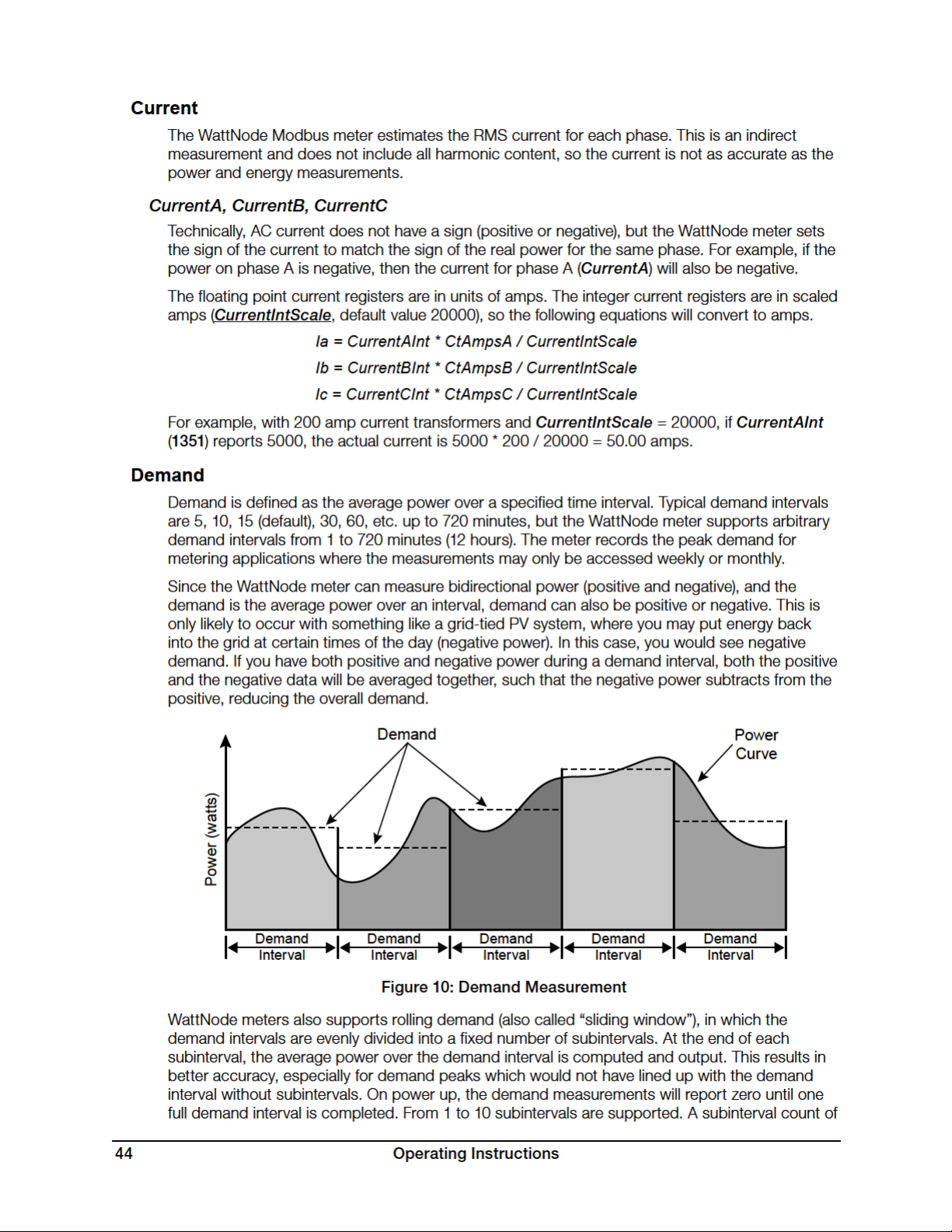
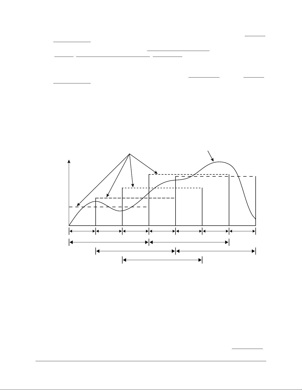
one (or zero) results in the standard demand measurement without rolling demand. See Configuration Registers for information on configuring the demand.
Any changes to the demand configuration (DemPerMins, DemSubints) or CT configuration
(CtAmps, CtAmpsA, CtAmpsB, CtAmpsC, CtDirections) will zero the reported demand and
start a new demand measurement. The DemandMin and DemandMax will not be reset by
configuration changes.
To manually zero some or all of the demand registers, see the ZeroDemand register in Configu-
ration Registers bel ow.
The floating point demand registers are reported in units of watts, while the integer demand
registers must be scaled by PowerIntScale to compute watts. To scale the integer Demand,
DemandA, DemandB, DemandC, DemandMin, DemandMax, or DemandApp, use the following equation:
Demand(W) = Demand • PowerIntScale
For example, if PowerIntScale (1609) is 100, and the integer Demand (1354) reports 4700, then
the demand is 4700 * 100 = 470,000 watts (or 470 kW).
Power
Demand
Curve
Power (watts)
Demand
Subinterval
Demand
Subinterval
Demand
Interval
Demand
Subinterval
Demand
Interval
Demand
Subinterval
Demand
Interval
Demand
Subinterval
Demand
Interval
Demand
Subinterval
Demand
Interval
Demand
Subinterval
Figure 11: Rolling Demand with Three Subintervals
Demand
The Demand register is updated at the end of every subinterval with the average PowerSum
over a full demand interval. After a power cycle or configuration change, Demand will report zero
until the completion of one full demand interval.
DemandA, DemandB, DemandC
The real power demand is computed for each phase from PowerA, PowerB, and PowerC.
DemandMin
The DemandMin is the smallest measured Demand (this may be negative for systems with
power generation). It is preserved across power failures and can be reset with the ZeroDemand
Operating Instructions 45

register. Note: there are no minimum or maximum demand registers for DemandA, DemandB,
and DemandC.
DemandMax
The DemandMax is the largest measured Demand. It is preserved across power failures and
can be reset with the ZeroDemand register.
DemandApp
DemandApp is computed the same way as Demand, but using apparent power.
I/O Pin Options
IoPinState, PulseCount
For details about the I/O pin options registers and configuration, see the Continental Control
Systems website: http://www.ccontrolsys.com/w/WattNode_Modbus_-_Option_IO.
Configuration Registers
ConfigPasscode (1601, 1602)
The WattNode Modbus meter has an optional configuration passcode to prevent unauthorized
changes to the configuration. As shipped from the factory, the ConfigPasscode is set to “0”,
disabling the passcode. If a passcode is set, the meter must be unlocked by writing the correct
value to ConfigPasscode before any configuration registers can be changed and before the
energy or demand registers can be reset to zero.
You can read the ConfigPasscode register to determine if the meter is locked. You cannot read
the actual passcode itself. If you lose your passcode, contact support for assistance.
● 0 - Unlocked
● 1 - Locked
Invalid unlock attempts will result in the Modbus exception 03 - “Illegal data value”, and prevent
more attempts for five seconds. An unlocked meter will become locked again after five minutes or
when “1” is written twice to ConfigPasscode.
The passcode can be set (or changed) by writing the new passcode to ConfigPasscode twice
within 30 seconds. If a passcode is already set, the meter must be unlocked first.
Valid passcode values are:
● 0 - this disables the passcode.
● 2 to 2,147,483,647 - use at least six digits for a secure passcode.
The passcode is a 32 bit value, so both register locations 1601 and 1602 must be written when
unlocking the WattNode or setting a passcode.
CtAmps (1603)
Writing the CtAmps register is a shortcut to quickly set CtAmpsA, CtAmpsB, and CtAmpsC
to the same value. If you read CtAmps and CtAmpsA, CtAmpsB, CtAmpsC are all identical,
then CtAmps will return the common value; otherwise it will return 0 (zero) to indicate there is no
common value.
CtAmpsA, CtAmpsB, CtAmpsC (1604 , 1605, 1606)
The CT amps registers are integer registers in units of amps used to set the rated current of the
attached current transformers (CTs). This allows the use of different CTs on different input phases:
ØA, ØB, and ØC. Rated current is the 100% value; the current that results in a 0.33333 VAC
output from the CT.
46 Operating Instructions

You can order the meter from the factory with the CtAmps preconfigured using Option CT=xxx
or Option CT=xxx/yyy/zzz if there are different CTs on phases A, B, and C. For example, Option
CT=100/100/50 sets CtAmpsA = 100, CtAmpsB = 100, and CtAmpsC = 50.
The specified rated CT amps for each phase (CtAmpsA, CtAmpsB, and CtAmpsC), affect the
scaling CurrentIntScale for the integer current registers CurrentA, CurrentB, and CurrentC.
See section Current (p. 44) above for details.
CtDirections (1607)
On occasion, current transformers are installed with the label “This side towards source” facing
the load instead of the source, or with the white and black wires swapped at the meter. If the
electrical installer notices this, they can fix it, but sometimes the problem isn’t noticed until the
electrician is gone and some or all of the reported power values are unexpectedly negative.
You can correct this with the CtDirections register:
● 0 - All CTs normal
● 1 - Flip phase A CT
● 2 - Flip phase B CT
● 4 - Flip phase C CT
● 3 - Flip phase A CT and flip phase B CT
● 5 - Flip phase A CT and flip phase C CT
● 6 - Flip phase B CT and flip phase C CT
● 7 - Flip all CTs (A, B, and C)
Flipping a CT with CtDirections will also reverse the status LED indications. So if the status LED
for a phase was flashing red and you flip the CT with CtDirections, the LED will change to green
flashing. This cannot be used to correct for situations where CT phases do not match the voltage
phases, such as swapping phases A and B on the current transformer inputs.
Averaging (1608)
The WattNode includes averaging for these registers: PowerSum, PowerA, PowerB, PowerC,
VoltAvgLN, VoltA, VoltB, VoltC, VoltAvgLL, VoltAB, VoltBC, VoltAC, Freq, PowerFactorAvg,
PowerFactorA, PowerFactorB, PowerFactorC, PowerReacSum, PowerReacA,
PowerReacB, PowerReacC, PowerAppSum, PowerAppA, PowerAppB, PowerAppC,
CurrentA, CurrentB, CurrentC.
Averaging is beneficial because it reduces measurement noise, and if the WattNode is being
polled less often than once a second (say once a minute), then the average over the last minute
provides a more accurate reading than just the data from the last second, which might be randomly high or low. Averaging is configured by setting the Averaging (1608) register to one of the
following values:
Averaging Register Description Averaging Period Update Rate
0 Fastest 1 second Every 1 second
1 Fast (default) 5 seconds Every 1 second
2 Medium 20 seconds Every 4 seconds
3 Slow 60 seconds Every 12 seconds
Table 9: Averaging Settings
When medium or slow averaging are specified, the reported values for averaged registers will only
update every 4 or 12 seconds respectively, instead of once a second.
Operating Instructions 47

PowerIntScale (1609)
In order to report power as an integer value (±32,767), the meter must scale the power so that it
doesn’t overflow. By default, the WattNode meter selects a PowerIntScale value of 1, 10, 100,
or 1000 whenever the CtAmps (or CtAmpsA, CtAmpsB, or CtAmpsC) are changed. The meter
selects a value that won’t overflow unless the power exceeds 120% of full-scale.
PowerIntScale Power Resolution Maximum Power Reading
0 (default) Auto-configure varies
1 1 watt ±32767 W
10 10 watt ± 3 27. 6 7 k W
100 100 watts ±3276.7 kW
1000 1000 watts ±32767 kW
Custom Values
You may also choose your own custom value for PowerIntScale including values that are not
multiples of 10.
If PowerIntScale is set to auto-configure, then reading PowerIntScale will show the actual scale
factor instead of 0.
To compute the actual power from integer power registers, use the following equation (note, there
is no scaling for the floating-point power registers, which always report power in watts):
ActualPower(W) = PowerRegister • PowerIntScale
PowerIntScale • 1 W ±(PowerIntScale • 32767 W)
Table 10: PowerIntScale Settings
PowerIntScale is used with the following registers: PowerSum, PowerA, PowerB, PowerC,
PowerReacSum, PowerReacA, PowerReacB, PowerReacC, PowerAppSum, PowerAppA,
PowerAppB, PowerAppC, Demand, DemandMin, DemandMax, DemandApp.
CurrentIntScale (1622)
When reporting current values as integers, the WattNode meter scales the current values so that
a current equal to the CT rated amps will result in an output value of CurrentIntScale. The default
CurrentIntScale is 20000. See CurrentA, CurrentB, CurrentC for more details.
Demand Configuration
DemPerMins, DemSubints (1610, 1611)
The variable DemPerMins sets the demand interval in minutes (default 15 minutes), and
DemSubints sets the number of demand intervals (default 1). The time period of each subinterval
is the demand interval divided by the number of subintervals. Setting DemSubints to 1 disables
subinterval computations. The demand period cannot be longer than 12 hours (720 minutes), and
a demand subinterval cannot be less than 1 minutes. The DemSubints can be set from 1 to 10.
An example configuration could use a demand period of 60 minutes with 4 subintervals. This
would result in a subinterval period of fifteen minutes. Every fifteen minutes, the average power
over the last hour would be computed and reported.
GainAdjustA, GainAdjustB, GainAdjustC (1612, 1613, 1614)
You may need to adjust the WattNode meter to match the results from a reference meter (such
as the utility meter) or to correct for known current transformer errors. The GainAdjust registers
effectively adjust the power, energy, and current calibration or registration for each phase.
The default values for the GainAdjust registers are 10,000, resulting in no adjustment. Setting
the value to 10,200 increases all the power, energy, and current readings from the meter by 2%
(10,200 / 10,000 = 102%). Setting the value to 9,800 decreases the readings by 2% (9,800 /
10,000 = 98%). The allowed range is from 5,000 to 20,000 (50% to 200%).
48 Operating Instructions

PhaseAdjustA, PhaseAdjustB, PhaseAdjustC (1615, 1616, 1617)
For maximum accuracy, there may be cases where you wish to compensate for the phase angle
error of the current transformers you are using. The PhaseAdjust registers allow the phase angle
to be adjusted on each phase by up to ±8 degrees in increments of one millidegree. For example,
if your CT causes a phase lead of 0.6 degrees (or 36 minutes), you could correct for this by
setting PhaseAdjustA, B, and C to -600, which subtracts 600 millidegree or 0.6 degree from the
phase lead. Use negative values to compensate for a phase lead in the CT (most common). The
default adjustment is 0.
CreepLimit (1618)
Creep refers to the situation where the wheel on an traditional electro-mechanical energy meter
moves even though there is no power being consumed. The WattNode meter has no wheel, but
all electrical systems have some noise, which can cause small readings in the absence of any
power consumption. To prevent readings due to noise, if the readings fall below the creep limit,
the meter forces the real and reactive power values to zero, and stops accumulating energy. This
is performed independently for each measurement phase using the following equation.
MinimumPower = FullScalePower / CreepLimit
Any measured power or reactive power below MinimumPower is forced to zero. FullScalePower is
defined as the nominal line-to-neutral VAC (see Specifications - Models (p. 55)) multiplied by
the full-scale or rated CT current.
Generally, the default value of 1500 (which sets the creep limit to 1/1500th of full-scale power)
works well. Sometime, in electrically noisy environments, you may see non-zero power readings
when the power should be zero. You can adjust the creep limit to eliminate this problem. For
example, to adjust the creep limit to 1/500th of full-scale (0.2%), set CreepLimit to 500.
PhaseOffset (1619)
The WattNode meter cannot directly measure line-to-line voltages (VoltAB, VoltBC, VoltAC,
VoltAvgLL). To estimate these voltages, the meter must know the phase offset of the electrical
service being measured. This setting has no effect on any other measurements or registers and is
only needed if you plan to monitor the line-to-line voltages.
PhaseOffset
(degrees)
0
60
90 Four-wire delta (wild leg): 120/208/240
120 (default) Three-phase: 120/208, 230/400, 277/480, 347/600
180
Single-phase (all line-to-line voltages will read zero). Use this setting when monitoring multiple independent branch circuits.
Three-phase grounded delta (grounded leg), where one phase is
connected to earth (rare)
Single-phase three-wire (mid-point neutral): 120/240
VoltAB will report the line-to-line voltage. VoltBC and VoltAC will
report zero regardless of the actual phase C voltage.
Table 11: PhaseOffset Values
Electrical Service Type
Zeroing Registers
ZeroEnergy (1620)
Writing 1 to ZeroEnergy will simultaneously set all of the energy registers to zero, except those
ending in “NR” (for non-resettable). They can also be set to zero or a preset value by writing the
desired value directly to each energy register. If a ConfigPasscode has been set, then you must
unlock the meter before you can zero or preset the energy.
Operating Instructions 49

As a security measure, there are three non-resettable energy registers—EnergySumNR,
EnergyPosSumNR, EnergyNegSumNR—that can never be reset to zero.
ZeroDemand (1621)
The ZeroDemand register can be written with three values (or zero which does nothing). If a
ConfigPasscode has been set, then you must unlock the meter before you can zero demand.
● 1 - Zero DemandMin and DemandMax registers.
● 2 - Zero Demand, DemandA, DemandB, DemandC and DemandApp registers. Start a
new demand interval.
● 3 - Zero DemandMin, DemandMax, Demand, DemandA, DemandB, DemandC and
DemandApp registers. Start a new demand interval.
I/O Pin Options Configuration
IoPinMode (1623)
For details about the I/O pin options registers and configuration, see the Continental Control
Systems website: http://www.ccontrolsys.com/w/WattNode_Modbus_-_Option_IO.
Communication Registers
Most customers will never need these registers, but they can be useful for special situations. If
you are using these registers to configure multiple WattNode meters, you may want to use the
broadcast address (0) so that all meters will update together. This isn’t permitted for setting the
address, because then multiple devices would share the same address.
The communication configuration can be restored to factory defaults by switching all the DIP
switches to the OFF position and leaving them OFF for 10 seconds, then setting them to the
desired address and baud rate.
ApplyComConfig (1651)
If any of the following communication configuration registers are changed, the new values will
not take effect until “1234” (decimal) is written to this register. This makes it easier to configure
multiple changes and have them all take effect together.
Reads of ApplyComConfig will return “1” if there are any pending changes, otherwise “0”.
Address (1652)
This register can override the DIP switch address setting and also allows addresses to be
assigned up to 247 (the DIP switches can only set addresses up to 127). Set this register back to
zero to use the DIP switch setting.
The meter can be ordered with Option AD, which factory assigns the address. See Option AD
(p. 20) in the section Setting the Modbus Address for details.
BaudRate (1653)
This register overrides the DIP switch baud rate setting for speeds up to 38,400 baud.
● 0 - Use DIP switch assigned baud rate (9,600 or 19,200 baud)
● 1 - 1,200 baud
● 2 - 2,400 baud
● 3 - 4,800 baud
● 4 - 9,600 baud
● 5 - 19,200 baud
● 6 - 38,400 baud
50 Operating Instructions

Test Equipment Depot - 800.517.8431 - 5 Commonwealth Ave, Woburn MA 01801 - TestEquipmentDepot.com
The meter can be ordered with Option 19K or Option 38K to preconfigure the baud rate to
19.200 or 38,400 baud. See Baud Rate (p. 20) for details.
ParityMode (1654)
The WattNode Modbus meter defaults to no parity, eight data bits, and one stop bit, but even
parity is supported using this register, or by ordering Option EP to preconfigure even parity
● 0 - N81 (no parity, one stop bit)
● 1 - E81 (even parity, one stop bit)
ModbusMode (1655)
● 0 - RTU - This is the default Modbus RTU binary protocol
● 1 - TCP-RTU - Emulates the Modbus TCP/IP binary protocol over RS-485
For some applications, it is desirable to convert the RS-485 to TCP/IP over Ethernet. The most
common approaches are the following:
1) Use a Modbus RTU RS-485 to Modbus TCP/IP Ethernet gateway. These devices can translate the RTU packets into Modbus TCP/IP packets and retransmit them over Ethernet. These
work well, but are specialized devices and somewhat expensive.
2) Use an RS-485 to Ethernet serial device adapter. These are less expensive than the Modbus
gateways, but they do not convert protocols from Modbus RTU to Modbus TCP/IP. Most
software designed to receive Modbus over an Ethernet connection will expect the Modbus
TCP/IP protocol. In order to make this work, the meter can switch to the Modbus TCP/IP
protocol (still using RS-485), which is nearly identical to Modbus RTU, but with a different
header and no CRC bytes (TCP/IP has a built-in CRC).
For more information on Modbus over TCP/IP, see “Modbus Messaging on TCP/IP Implementation Guide - V1.0b”. Implementing a system using Modbus TCP/IP may be complex, so see
http://www.ccontrolsys.com/w/WattNode_Modbus_-_Option_TCP-RTU and contact Continental
Control Systems for assistance.
The meter can be ordered with Option TCP‑RTU to preconfigure the TCP-RTU mode.
ReplyDelay (1656)
ReplyDelay configures a user-defined minimum Modbus reply delay between 5 and 180 millisec-
onds (the default is 5 milliseconds). This is useful with some Modbus master devices or software
that can miss response data if the meter responds to a request too quickly.
Diagnostic Registers
SerialNumber (1701, 1702 )
This is a 32 bit long integer register containing the meter’s serial number, as printed on the label.
UptimeSecs (1703, 1704)
This 32 bit long integer counts the number of seconds the meter has been running since the last
power failure or reset. Resets can be caused by power brownouts or severe errors.
TotalSecs (1705, 1706)
This 32 bit long integer counts the total seconds of meter operation since factory calibration.
Operating Instructions 51

Model (1707 )
This register can be used to determine the WattNode model.
● 201 - WNC-3Y-208-MB
● 202 - WNC-3Y-400-MB
● 203 - WNC-3Y-480-MB
● 204 - WNC-3Y-600-MB
● 205 - WNC-3D-240-MB
● 206 - WNC-3D-400-MB
● 207 - WNC-3D-480-MB
Version (170 8 )
This reports the WattNode Modbus meter firmware version. The firmware is not field upgradable.
Options (170 9)
This register indicates factory configured options. For details, see
http://www.ccontrolsys.com/w/WattNode_Modbus_Option_Identification.
PowerFailCount (1711)
This counts (up to 32767) the number of times power has been cycled on this meter.
Communication Error Counts
The following registers report communication error counts. Each register counts up to 32767 and
stops. All four of these registers are reset to zero whenever power is cycled or by writing zero to
any of them.
CrcErrorCount (1712 )
This is the number (up to 32767) of packets with an invalid CRC (cyclic redundancy check).
FrameErrorCount (1713)
This is the number (up to 32767) of Modbus packets with framing errors. A framing error can indicate bad baud rate, bad parity setting, RS-485 noise or interference, or an RS-485 bus collision.
PacketErrorCount (1714)
This counts (up to 32767) the number of Modbus packets that could not be parsed.
OverrunCount (1715)
This counts (up to 32767) the number of times the Modbus input buffer has been overrun. The
buffer is 256 bytes and normal requests are less than 80 bytes, so an overrun normally indicates
non-Modbus traffic on the RS-485 bus or severe noise on the bus.
Error Codes
ErrorStatus (1710 )
ErrorStatus1 ‑ ErrorStatus8 (1716 - 1723)
The ErrorStatus registers hold queues of the most recent eight errors or status notifications.
ErrorStatus allows access to the eight most recent errors from a single Modbus register. Each
time you read it, you’ll get another value (starting with the oldest). When there are no more
errors, ErrorStatus will report 0. The ErrorStatus values are preserved across power failures.
ErrorStatus is generally best used with unattended data logging, since each error will only be
reported once.
52 Operating Instructions

ErrorStatus1 through ErrorStatus8 also list the eight most recent errors, but with a few differences. ErrorStatus1 lists the most recent error or status, while ErrorStatus8 lists the
oldest. Reading these registers won’t change the reported values for ErrorStatus1 through
ErrorStatus8, so they can be read repeatedly without clearing the values. ErrorStatus1 through
ErrorStatus8 can all be cleared by writing 0 to any of them. They are not preserved across
power failures. ErrorStatus1 through ErrorStatus8 are generally best used when a person will
be looking at the values in real time, because they provide a visual history of recent errors and
events and will not be cleared when they are read.
The following lists many of the error and status code values. For any not listed or those marked
“ERROR” contact technical support.
● 0: No error or status messages.
● 1-49, 50-58, 60-61, 71-73: ERROR: Internal firmware error. Contact technical support.
● 59: ERROR: Non-volatile data lost: energy, peak demand, etc.
● 62-66: WARNING: Internal energy measurement overflow
● 67: ERROR: Calibration data lost. Meter will not function until it is recalibrated.
● 68: ERROR: Configuration data lost (CtAmps, etc.)
● 69: WARNING: Could not measure AC line frequency, may indicate high noise condition.
● 70 , 74: ERROR: Non-volatile memory failure: energy, demand, etc. will be lost when power
fails.
● 75-77: ERROR: Internal measurement error.
● 78-83: WARNING: Measured high AC line voltage. Sustained high voltage may damage the
WattNode.
● 84, 85, 86: INFO: EnergyA, B, C registers overflowed 100 gigawatt-hours, reset to 0.
● 87: INFO: EnergySum register overflowed 100 gigawatt-hours, reset to 0.
● 88: INFO: EnergySumNR register overflowed 100 gigawatt-hours, reset to 0.
● 89, 90, 91: INFO: EnergyReacA, B, C registers overflowed 100 gigawatt-hours, reset to 0.
● 92: INFO: EnergyReacSum register overflowed 100 gigawatt-hours, reset to 0.
● 93, 94, 95: INFO: EnergyPosA, B, C registers overflowed 100 gigawatt-hours, reset to 0.
● 96: INFO: EnergyPosSum register overflowed 100 gigawatt-hours, reset to 0.
● 97: INFO: EnergyPosSumNR register overflowed 100 gigawatt-hours, reset to 0.
● 98, 99, 100: INFO: EnergyNegA, B, C registers overflowed 100 gigawatt-hours, reset to 0.
● 101: INFO: EnergyNegSum register overflowed 100 gigawatt-hours, reset to 0.
● 102: INFO: EnergyNegSumNR register overflowed 100 gigawatt-hours, reset to 0.
● 103, 104, 105: INFO: EnergyAppA, B, C registers overflowed 100 gigawatt-hours, reset to 0.
● 106: INFO: EnergyAppSum register overflowed 100 gigawatt-hours, reset to 0.
● 107: INFO: PulseCount register overflowed from 4,294,967,295 to zero.
● 197: WARNING: Tried to write to read-only register.
● 198: WARNING: IoPinMode write not allowed because required option not installed.
● 199: WARNING: IoPinState write command rejected because IoPinMode is an input.
● 200: WARNING: Configuration register cannot be changed without entering
ConfigPasscode first.
● 202: WARNING: ConfigPasscode update failed because second write (verify) did not match
the first write.
● 203: WARNING: A write to a dual register (typically ConfigPasscode) was aborted.
● 205: WARNING: Invalid ConfigPasscode entered.
● 206: WARNING: Invalid Modbus register address specified.
Operating Instructions 53

● 207: WARNING: Invalid Modbus register data value specified.
● 208: WARNING: Invalid configuration register value specified.
● 209: INFO: ConfigPasscode unlock attempt rejected because it was within five seconds of a
previous failed attempt.
● 211: WARNING: Invalid Modbus write length specified.
● 212: WARNING: Invalid Modbus single-register write length specified
● 213: WARNING: Invalid Modbus function code specified.
● 215: WARNING: Slave device failure exception occurred: ConfigPasscode required, etc.
● 216: ERROR: Custom register map error. Custom map disabled.
● 220: INFO: Factory reset of energies completed.
● 241: WARNING: Invalid Modbus TCP/IP header.
● 242, 246: WARNING: Modbus collision. The meter received extra data after receiving a com-
mand. This may indicate an address conflict or electrical interference.
● 243: WARNING: Invalid Modbus message length.
● 244: WARNING: Timeout receiving the Modbus TCP header (only applies in TCP-RTU mode).
● 245: WARNING: Invalid length in the Modbus TCP header (only applies in TCP-RTU mode).
● 247: WARNING: RS-485 parity error. Generally caused by baud rate mismatch, parity mode
mismatch, or electrical interference.
● 248: WARNING: RS-485 bus contention during transmit. Generally caused by two or more
WattNode meters with duplicate Modbus addresses.
● 249: WARNING: Duplicate Modbus address detected.
● 250: WARNING: Modbus receiver overrun. This is generally caused by non-Modbus data on
the bus or packets longer than 256 bytes.
● 251: WARNING: RS-485 receiver error. Generally caused by baud rate mismatch, parity
mode mismatch, or electrical interference.
● 252-253: WARNING: Short Modbus packet detected (less than four bytes). Modbus RTU
uses a brief pause (3.5 byte periods) to indicate the end of a packet, so any break in the
stream of bytes can cause this, such as hot-connecting the RS-485 lines.
● 254: WARNING: False Modbus start bit. This generally indicates electrical noise, or inad-
equate termination or biasing. See Termination and Biasing sections under Connecting
Modbus Outputs (p. 20) for more information.
● 255: WARNING: Invalid Modbus packet cyclic redundancy check (CRC). This generally
indicates electrical noise on the RS-485 bus.
Maintenance and Repair
The WattNode Modbus meter requires no maintenance. There are no user serviceable or replaceable parts except the pluggable screw terminals.
The WattNode meter should not normally need to be cleaned, but if cleaning is desired, power
must be disconnected first and a dry or damp cloth or brush should be used.
The WattNode meter is not user serviceable. In the event of any failure, the meter must be
returned for service (contact CCS for an RMA). In the case of a new installation, follow the diagnostic and troubleshooting instructions before returning the meter for service, to ensure that the
problem is not connection related.
54 Operating Instructions

Specifications
Models
Model
WNC-3Y-208-MB
RWNC-3Y-208-MB
WNC-3Y-400-MB
RWNC-3Y-400-MB
WNC-3Y-480-MB
RWNC-3Y-480-MB
WNC-3Y-600-MB
RWNC-3Y-600-MB
WNC-3D-240-MB
RWNC-3D-240-MB
WNC-3D-400-MB
RWNC-3D-400-MB
WNC-3D-480-MB
RWNC-3D-480-MB
* Note: the delta models have an optional neutral connection that may be used for measuring
wye circuits. In the absence of neutral, voltages are measured with respect to ground. Delta
WattNode models use the phase A and phase B connections for power.
Nominal Vac
Line-to-Neutral
120 208–240 3 4
230 400 3 4
277 480 3 4
347 600 3 4
120 * 208–240 3 3–4
230* 400 3 3–4
277* 480 3 3–4
Table 12 : WattNode Models
Nominal Vac
Line-to-Line
Model Options
Any of these models are available with the following options. See the CCS website
WattNode Modbus - Options page for details.
Phases Wires
General Options
Option CT=xxx: Pre-assign xxx as the global CtAmps value of the attached current
transformers.
Option CT=xxx/yyy/zzz: Pre-assign xxx to CtAmpsA, yyy to CtAmpsB, and zzz to CtAmpsC.
This is used if non-matching CTs are connected to different phases.
Communication Options
Option EP: Factory configure the Modbus RS-485 communications to even parity (E81).
Parity: even
Data bits: 8
Stop bits: 1
Option 19K: Factory configure the RS-485 communications 19,200 baud. Position 8 of the DIP
switch will be ignored.
Option 38K: Factory configure the RS-485 communications to 38,400 baud. Position 8 of the
DIP switch will be ignored.
Option TCP-RTU: Configure the communications to the Modbus TCP-RTU protocol option for
use with RS-485 to Ethernet gateways (serial device adapters).
Option AD: Factory configure the Modbus address. The DIP switch address will be ignored.
Specifications 55

X Terminal Options
These options all utilize the X (auxiliary) terminal on the MODBUS connector:
Option X5: Provides 5 Vdc at up to 60 milliamps between the C (common) and X (5 V) terminals.
Output Voltage: 5 Vdc ± 5%
Minimum Output Current: 0 mA
Maximum Output Current: 60 mA
Maximum Short-Circuit Output Current: 150 mA
Recommended Maximum 5 V Wire Length: 30 cm (1 foot)
Option IO: Provides a digital input (level sensing and pulse counting) or output (for load shedding
and other applications) on the X terminal.
Option SSR: Provides a solid-state relay (contact closure) output between the X and C terminals
for load shedding and other applications.
Special Options
Contact the factory about the following special options:
Option 232: Provide RS-232 I/O in place of RS-485.
Option TTL: Provide 5 V TTL UART I/O in place of RS-485.
Accuracy
The following accuracy specifications do not include errors caused by the current transformer
accuracy or phase angle errors. “Rated current” is the current that generates a CT output voltage
of 0.33333 Vac.
Condition 1 ‑ Normal Operation
Line voltage: -20% to +15% of nominal
Power factor: 1.0
Frequency: 48 - 62Hz
Ambient Temperature: 25°C
CT Current: 5% - 100% of rated current
Accuracy: ±0.5% of reading
Condition 2 ‑ Low CT Current
All conditions the same as Condition 1 except:
CT Current: 1% - 5% of rated current
Accuracy: ±1.0% of reading
Condition 3 – Very Low CT Current
All conditions the same as Condition 1 except:
CT Current: 0.2% - 1% of rated current
Accuracy: ±3.0% of reading
Condition 4 ‑ High CT Current
All conditions the same as Condition 1 except:
CT Current: 100% - 120% of rated current
Accuracy: ±1.0% of reading
Condition 5 ‑ Low Power Factor
All conditions the same as Condition 1 except:
Power factor: 0.5 (±60 degree phase shift between current and voltage)
56 Specifications

Additional Error: ±0.5% of reading
Condition 6 ‑ Temperature Variation
All conditions the same as Condition 1 except:
Ambient Temperature: -30°C to +55°C
Additional Error: ±0.75% of reading
Measurement
Creep Limit: 0.10% (1/1000th) of full-scale. Whenever the power or reactive power for a phase
drops below the creep limit, the power or reactive power for the phase will be forced to zero.
Also, if the line voltage for a phase drops below 20% of nominal Vac, the output power for the
phase will be set to zero. These limits prevent spurious readings due to measurement noise.
To customize the creep limit, see CreepLimit (1618) in Configuration Registers (p. 46).
Update Rate: 1.0 second. Internally, all measurements are performed at this rate.
Start-Up Time: Approximately 1.0 second. The meter starts measuring 50-100 milliseconds after
AC power is applied, but requires a full 1.0 second measurement cycle before it starts reporting data. The WattNode meter does not respond to Modbus packets during this start-up time.
Current Transformer Phase Angle Correction: 1.0 degree leading. Current transformers (CTs)
typically have a leading phase angle error ranging from 0.2 degrees to 2.5 degrees. The
WattNode meter is normally programmed to correct for a 1.0 degree phase lead to provide
good accuracy with typical CTs. The CT phase angle correction can be changed using the
PhaseAdjustA, PhaseAdjustB, PhaseAdjustC registers.
Over-Voltage Limit: 125% of nominal Vac. If the line voltage for one or more phases exceeds this
limit, the status LEDs for these phases will flash alternating red-green as a warning. Extended
over-voltage operation can damage the meter and void the warranty. See Line Voltage Too
High (p. 24).
Over-Current Limit: 120% of rated current. Exceeding 120% of rated current will not harm the
WattNode meter but the current and power will not be measured accurately.
Modbus Communication
Protocol: Modbus RTU (binary)
Baud Rates: 1200, 2400, 4800, 9600, 19200, and 38400
Duplex: Half (two-wire plus common)
Polarity Auto-detect: will automatically correct swapped A- and B+ terminals provided network
has at least 200 millivolt bias between A- and B+.
Parity:
Standard: N81 (no parity, eight data bits, one stop bit)
Optional: E81 (even parity, eight data bits, one stop bit)
Modbus Buffer: 256 by tes
Communication Response Time: 5 - 25 milliseconds (may be longer immediately after a
Modbus write command while values are saved to non-volatile memory).
EIA RS-485 Interface:
RS-485 Output Isolation: 4500 Vac RMS
Driver Output Voltage (Open Circuit): ±6 Vdc maximum
Driver Output Voltage (54 Ω load): ±1.5 Vdc minimum
Driver Output Current (54 Ω load): ±60 mA typical
Driver Output Rise Time (54 Ω || 50 pF load): 900 nS typical
Receiver Common-Mode Voltage Range: -7 Vdc to +12 Vdc maximum
Specifications 57

Receiver Sensitivity: ±200 mV
Receiver Bus Load: 1/8 unit load (up to 256 WattNode meters per subnet)
Receiver Failsafe Modes: bus open, bus shorted, bus idle
Electrical
Power Consumption: The following table shows typical power consumption and power factor
values with all three phases powered at nominal line voltages. The power supply draws
most of the total power consumed, while the measurement circuitry draws 1-10% of the total
(6-96 milliwatts per phase, depending on the model). Due to the design of the power supply,
WattNode meters draw slightly more power at 50 Hz.
Real
Model
Power
(60 Hz)
WNC-3Y-208-MB 1.5 W 1.8 W 0.79 4 VA 96 – 138
WNC-3Y-400-MB 1.6 W 1.8 W 0.73 4 VA 184 – 264
WNC-3Y-480-MB 1.6 W 2.0 W 0.69 4 VA 222 – 318
WNC-3Y-600-MB 1.0 W 1.3 W 0.76 4 VA 278 – 399
WNC-3D-240-MB 1.2 W 1.5 W 0.70 4 VA 166 – 276
WNC-3D-400-MB 1.1 W 1.4 W 0.67 3 VA 320 – 460
WNC-3D-480-MB 1.2 W 1.6 W 0.70 3 VA 384 – 552
Real
Power
(50 Hz)
Power
Factor
Rated
(1)
VA
Power
Supply
Range (Vac)
Power
Supply
Terminals
N and ØA
N and ØA
N and ØA
N and ØA
ØA and ØB
ØA and ØB
ØA and ØB
Table 13 : Power Supply Characteristics
(1)
Note: This is the maximum at 115% of nominal Vac at 50 Hz. This is the same as the value that
appears on the front label of the meter.
Maximum Power Supply Voltage Range: -20% to +15% of nominal (see table above). For the
WNC-3D-240-MB, this is -20% of 208 Vac (166 Vac) to +15% of 240 Vac (276 Vac).
Operating Frequencies: 50/60Hz
Measurement Category: CAT III
Measurement category III is for measurements performed in the building installation. Examples
are measurements on distribution boards, circuit-breakers, wiring, including cables, bus-bars,
junction boxes, switches, socket-outlets in the fixed installation, and equipment for industrial
use and some other equipment, for example, stationary motors with permanent connection to
the fixed installation.
The line voltage measurement terminals on the meter are rated for the following CAT III voltages (these ratings also appear on the front label):
Model CAT III Voltage Rating
WNC-3Y-208-MB
WNC-3D-240-MB
WNC-3Y-400-MB
WNC-3D-400-MB
WNC-3Y-480-MB
WNC-3D-480-MB
WNC-3Y-600-MB 600 Vac
Table 14: WattNode CAT III Ratings
Current Transformer Inputs:
Nominal Input Voltage (At CT Rated Current): 0.33333 Vac RMS
Absolute Maximum Input Voltage: 5.0 Vac RMS
Input Impedance at 50/60Hz: 23 kΩ
58 Specifications
240 Vac
400 Vac
480 Vac

Certifications
Safety: UL 61010-1; CAN/CSA-C22.2 No. 61010-1-04; I EC 61010-1
Immunity: EN 61326: 2002 (Industrial Locations)
Electrostatic Discharge: EN 61000-4-2: 4 kV contact, 8 kV air: (B) Self-Recovering
Radiated RF Immunity: EN 61000-4-3: 10 V/m: (A) No Degradation
Electrical Fast Transient / Burst: EN 61000-4-4: 2 kV: (B) Self-Recovering
Surge Immunity: EN 61000-4-5: 1 kV I/O, 4 kV AC: (B) Self-Recovering
Conducted RF Immunity: EN 61000-4-6: 3 V: (A) No Degradation
Voltage Dips, Interrupts: EN 61000-4-11: (B) Self-Recovering
Emissions: FCC Part 15, Class B; EN 55022: 1994, Class B
Environmental
Operating Temperature: -30°C to +55°C (-22°F to 131°F)
Altitude: Up to 2000 m (6560 ft)
Operating Humidity: non-condensing, 5 to 90% relative humidity (RH) up to 40°C, decreasing
linearly to 50% RH at 55°C.
Pollution: POLLUTION DEGREE 2 - Normally only non-conductive pollution; occasionally, a
temporary conductivity caused by condensation must be expected.
Indoor Use: Suitable for indoor use.
Outdoor Use: Suitable for outdoor use when mounted inside an electrical enclosure (Hammond
Mfg., Type EJ Series) that is rated NEMA 3R or 4 (IP 66).
Mechanical
Enclosure: High impact, ABS and/or ABS/PC plastic
Flame Resistance Rating: UL 94V-0, IEC FV-0
Size: 153 mm × 85 mm × 38 mm (6.02 in × 3.35 in × 1.50 in)
Weight: 307 gm (10.8 oz)
Connectors: Euroblock style pluggable terminal blocks
Green: up to 12 AWG (2.5 mm2), 600 V
Black: up to 12 AWG (2.5 mm2), 300 V
Current Transformers
WattNode meters use CTs with built-in burden resistors generating 0.33333Vac at rated AC current. The maximum input current rating is dependent on the CT model. Exceeding the maximum
input current rating may damage the CT, but should not harm the meter.
None of these CTs measure DC current and the accuracy can be degraded in the presence of DC
currents, as from half-wave rectified loads. The solid-core CTs are most susceptible to saturation
due to DC currents. Rogowski coil CTs do not measure DC, but their accuracy is not degraded by
DC.
To meet the UL listing requirements, the WattNode meter may only be used with these UL listed
or recognized current transformer models. These all generate 333.33 millivolts AC at rated current. See the current transformer datasheets for CT ratings.
ACT-0750-xxx
C T L-125 0 - xxx
CTM-0360-xxx
CTS-0750-xxx
CTS-1250-xxx
CTS-2000-xxxx
CTB-WxL-xxxx
C T B L- WxL-xxxx
CTT-0300-xxx
CTT-0500-xxx
CTT-0750-xxx
CTT-1000-xxx
CT T-125 0 -xxx
CTRC-yyyyy-xxxx
Specifications 59

● “xxx” indicates the full scale current rating.
● “WxL” indicates the opening width (W) and leg length (L) in inches.
● “dddd” indicates the opening diameter of the loop for flexible Rogowski CTs.
● “yyyyy” indicates the opening size in mils (thousandths of inches).
Common CT Specifications
Type: voltage output, integral burden resistor
Output Voltage at Rated Current: 0.33333 Vac (one-third volt)
Standard CT Wire Length: 2.4 m (8 feet)
Warranty
All products sold by Continental Control Systems, LLC (CCS) are guaranteed against defects in
material and workmanship for a period of five years from the original date of shipment. CCS’s
responsibility is limited to repair, replacement, or refund, any of which may be selected by CCS at
its sole discretion. CCS reserves the right to substitute functionally equivalent new or serviceable
used parts.
This warranty covers only defects arising under normal use and does not include malfunctions or
failures resulting from: misuse, neglect, improper application, improper installation, water damage,
acts of nature, lightning, product modifications, alterations or repairs by anyone other than CCS.
Except as set forth herein, CCS makes no warranties, expressed or implied, and CCS
disclaims and negates all other warranties, including without limitation, implied warranties
of merchantability and fitness for a particular purpose.
Limitation of Liability
In no event shall CCS be liable for any indirect, special, incidental, punitive or consequential damages of any kind or nature arising out of the sale or use of its products whether
such liability is asserted on the basis of contract, tort or otherwise, including without
limitation, lost profits, even if CCS has been advised of the possibility of such damages.
Customer acknowledges that CCS’s aggregate liability to Customer relating to or arising
out of the sale or use of CCS’s products, whether such liability is asserted on the basis of
contract, tort or otherwise, shall not exceed the purchase price paid by Customer for the
products in respect of which damages are claimed. Customer specifically acknowledges
that CCS’s price for the products is based upon the limitations of CCS’s liability set forth
herein.
60 Warranty
Test Equipment Depot - 800.517.8431 - 5 Commonwealth Ave, Woburn MA 01801 - TestEquipmentDepot.com
 Loading...