

CCS LDLB-IP series, LDLB-IP-300SW-N, LDLB-300RD-N, LDLB series, LDLB-300SW-N Instruction Manual
...Page 1
- 1 -
LDLB/LDLB-IP Series
Bar Lights
Instruction Guide
Thank you for p urchasing a CC S product. To ensure p roper use of
the produc t, please read this inst ruction guide befor e use and keep
it for your fut ure reference.
These LED Ligh t Units feature integrated li ght control and ON/OF F control circuits.
The LEDs are dr iven with a constant-c urrent system and the light i s set to any of 100 levels with variab le-current cont rol.
You can change bet ween Constant Lighting M ode and Overdrive Mode.
You can manually set th e light intensity from th e operating panel or set it wi th an analog input (0 to 10 V) from an ex ternal device.
You can daisy-ch ain up to three Light Units to pr ovide power and externall y control the light intens ity of all of the Light Units to gether.
The LDLB- IP Series provides I P67 water resistance.
Features
The followi ng symbols indicate an d classify the prec autions in the
Instruction Guide.
PROHIBITED
DISASSEMBLY
PROHIBITED
DO NOT TOUCH
WITH WET HANDS
DO NOT SUBJECT
TO MOISTURE
MANDATORY
ACTIONS
These symbols indicate
prohibited actions.
This symbol i ndicates
required actions.
This produc t has been design ed with full co nsideration of s afety. However, incorr ect usage of the pr oduct may result i n
re, electr ic shock, or other seri ous accidents. Obser ve the following prec autions.
Warning
Indicates t hat incorrect
usage may resu lt in
serious injury or death.
Caution
Indicates that incorrect
usage may result in injury
or property damage.
The follow ing symbols are used in t his Instructio n Guide to indicate
and classify the relative importance of warnings and cautions.
Caution
Do not drop th e product
or subject it t o impact.
Doing so may c ause the
product to malfunction.
PROHIBITED
Do not bundle p roduct
cables wit h highvoltage
lines or powe r lines.
Doing so may c ause the
product to malfunction.
Allow leeway between
the cables when
installing them.
MANDATORY
ACTIONS
Be careful o f static
electricity. Damage
to the LED light m ay
occur, if a person
charged with static
electricity touches it.
Keep the prod uct away
from all items charged
with static electricity.
PROHIBITED
Before moving the
product, disconnect
all connecting cables.
Damaging the cables
may result in f ire or
electric shock.
MANDATORY
ACTIONS
Do not bend a ca ble
past its natural bending
radius or jam a c able
into a narrow space
when wiring the
product. Doing so may
cause product failure.
PROHIBITED
Always hold o nto the
plug or conn ector when
disconnecting the
cables. Pu lling on the
cable may dam age the
cable and re sult in fire
or electric shock.
MANDATORY
ACTIONS
Do not intentionally
short-circuit the
positive and negative
output terminals.
PROHIBITED
If there is dus t or other
foreign mat ter on the
electro des, turn OFF
the power sup ply and
then use a dr y cloth
to remove the du st or
foreign mat ter. Failure to
do so may result i n re.
MANDATORY
ACTIONS
Be sure to use th e
product within the
range of inpu t voltage.
Applying t he voltage
beyond the ran ge may
cause product failure.
PROHIBITED
Do not wipe th e product
with organ ic solvent s,
such as paint t hinner or
benzene. Discoloration
or deterioration of the
product surfaces may
occ ur.
PROHIBITED
1
2
3
4
5
6
Important Information for Equipment Safety
Confirming Product Information
Names and Functions of Parts
Connections
Setting the Light Intensity on the Operating Panel
External Control of the Light Intensity
- Read Before Use -
Warning
Do not disassemble
or modify t he product.
Doing so may re sult in
re or elect ric shock.
DISASSEMBLY
PROHIBITED
LED light radi ation may
cause cor neal or retinal
abnormalities if you
look direc tly at the light.
To prevent harmful l ight
exposure, neve r look
directly at t he LED light.
MANDATORY
ACTIONS
Do not conne ct or
disconnect the Light
Unit and cables with
wet hands. Doi ng so
may result in el ectric
shock.
DO NOT TOUCH
WITH WET HANDS
This product generates
high temperatures. Do
not touch the p roduct
while it is tur ned on or
immediate ly after it is
turned of f, or burning
may result. Pr ovide
cooling wi th a fan or
other ventil ation if the
product is t o be used in
a closed space.
MANDATORY
ACTIONS
Using LDLB-series
Light Unit s (not water
resistant)
Make sure that t he
product is f ree of moisture
or any liquid. E xposure to
water may resul t in fire,
electric shock.
DO NOT SUBJECT
TO MOISTURE
Connect or disconnect
the light ca ble only after
turning of f the power
supply. Failure to do
so may result in c ircuit
damage, fire caused
by a minute spar k, or
electric shock.
MANDATORY
ACTIONS
If abnorma l condition o ccurs such as f uming, heat, sm ell,
noise, or so on , stop using the pr oduct immedi ately, and
turn off th e power supply. A fi re or electri c shock may
result if the p roduct is kept used.
MANDATORY
ACTIONS
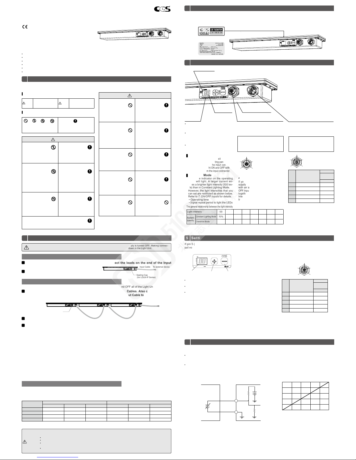
The followi ng label is attached to the L ED light. The color of the la bel indicates the lumine scence color of the pro duct. The name
label spe cies the model name, power consump tion, and serial number. Be sure to che ck the contents b efore using the pr oduct
and handle the l abel with care. If the labe l is missing or damaged and t he contents cannot be ch ecked, please contact C CS Inc.
Connecting One Light Unit
Daisy-chaining Two or Three Light Units
Maximum Cable Length
Before you co nnect the Input Cable or L ink Cable, make sur e that the power supply is tur ned OFF. Making connec-
tions with t he power supply turn ed ON may result in re, e lectric shock, o r breakdown in the Lig ht Unit.
Handle the L ight Units and conn ectors with care. D o not deform or damag e the connectors .
Connect t he cables corre ctly to the Light Unit s.
Connect a S ealing Cap to any ou tput connec tors to which a c able is not conn ected to mainta in water resist ance. The
Sealing Cap i s connected to the o utput connector w hen the Light Unit is sh ipped.
If the Light Un it is not used for a long pe riod of time with the c able disconnect ed, attach the Cap to th e connector or take
other measures to maintain water resistance.
Observe t he following prec autions to prevent el ectrical shoc k and accidents fro m water entry.
Using LDLB -IP-series Li ght Units
Warning
Caution
1
1
2
2
You can daisy-ch ain up to three Light Units to set t he light intensities or tur n ON and OFF all of the Light Uni ts together.
The maximum l ength of the 24-VDC power s upply cable depends on th e wire diameter, operat ing mode, and number of con nected Light U nits. The maximum cabl e lengths are given in the fol lowing table.
One Light Unit C onnected: The table give s the maximum length of th e Input Cable.
Two or Three Light Unit s Connected: The table gi ves the maximum total len gth of the Input Cable and Link C ables.
Connect t he Input Cabl e to the input co nnector and c onnect the l eads on the en d of the Input
Cable to an ex ternal devic e.
Connect t he output and i nput connec tors of the Lig ht Units with L ink Cables. Al so connect th e Input
Cable to th e input connec tor and conne ct the leads o n the end of the In put Cable to an ex ternal devi ce.
Turn ON the power sup ply.
Turn ON the power sup ply.
Changing fr om Constant Li ghting Mode t o Overdrive Mo de
1) Set the ON/OFF inp uts from the exte rnal device to th e status for turni ng ON the Light Uni t in Constant Ligh ting Mode.
Refer to 7. ON/OFF Inp uts for information on th e ON/OFF input.
2) Change the ope rating modes in order fro m the Light Unit that is far thest from the power supp ly.
(In the above gur e, the order would be Light Un it A, Light Unit B, and then Li ght Unit C.)
Refer to 3. Name s and Functions of Pa rts for infor mation on chan ging the operat ing mode. If the set ting status of th e
ON/OFF inpu ts is not correc t, an overdrive error will oc cur when you change the ope rating mode. Also, if the ord er is not
correct , an overload error will oc cur.
Changing fr om Overdrive M ode to Constan t Lighting Mo de
1) Change the opera ting modes in order from t he Light Unit that is nearest to t he power supply.
(In the above gur e, the order would be Light Un it C, Light Unit B, and then Light U nit A.)
Refer to 3. Names an d Functions of Parts for inf ormation on changing t he operating mode. If the ord er is not correct,
an overload er ror will occur. The settin g status of the ON/OFF input s is not relevant.
To external device
Input Cable
Link CableLink Cable
Light Unit A Light Unit B Light Unit C
Sealing Cap
(for LDLB-IP Series)
When you daisy- chain Light Un its, you must use the o perating pane l on each Light Unit t o change betwee n Constant
Lighting Mo de and Overdrive Mode. Use t he following procedur e to change the operating m ode.
To external device
Input Cable
Sealing Cap
(for LDLB-IP Series)
Connection Example
LDLB Light UnitExternal Circuit
Variable power supply
(0 to 10 VDC)
24 VDC
* You can adjust the li ght intensity wit h a variable power supp ly or a variable
resistor.
*
If you use a varia ble power supply, use a pow er supply with a sinki ng
output of 3 mA minimum per Light Unit.
Pin 5
Pin 3
If you use a varia ble resistor, use the on e specified bel ow.
One Light Uni t: 15 kΩ
Two Light Units: 10 kΩ
Three Light U nits: 5 kΩ
Do not exceed an a llowable differ ence of 20% in the overa ll resistance.
Note:
Accordin g to product speci fications, the l ight intensity tha t is set on
the operati ng panel may be used whe n the resistance is n ear the
maximum value.
If pin 5 (analog inp ut) and pin 3 (common grou nd) are not connec ted on the input co nnector or if 13 to 24 V (maxi mum in-
put voltage: 26 .4) is input, you can use the + and − swi tches on the operating pa nel to manually set the light in tensity.
If 0 to 10 V is applied b etween pin 5 (analog i nput) and pin 3 (common gr ound) on the input c onnector, you can set t he light
intensity to a ny of 100 levels with the voltage o f the analog input.
The light inten sity is displayed o n the digital dis play between 00 a nd 99
(100 levels) .
If you hold do wn the + or − key for m ore than 1 second, the value will
change faster.
The manually s et light intensit y is saved internall y even after you turn
OFF the power sup ply or after you ch ange to external l ight intensity
control with an analog input.
The light inten sity is displayed on the digi tal display between 00 a nd 99 (100 levels).
To maintain the light i ntensity, continu e to input a constan t voltage. The ligh t intensity that i s set by the analog inp ut is not
stored in the Li ght Unit.
Note: Depend ing on the numbe r of connected L ight Units and th e cable lengt h, different l ight intensiti es may be set for the s ame analog
input voltage.
Note: The digi tal display will show " --" if the light is tu rned OFF in Constan t Lighting Mode. If you t urn the light ON and OF F repeatedly over
a short per iod of time, the digi tal display may not disp lay numbers corr ectly.
MODE
OverDrive Continuous
: Hold down
L
E
V
E
L
O/D
Con
Input Con nector (M12 Plug) Congur ation
Settin g the Light Intensi ty with an Analog I nput
Voltage (V ) between Pin 5 and 3
Light intensity
0
99
20
40
59
79
2 4 6 8 10
5
4
1
3
2
3
Set the ope rating mode s of the Light Uni ts.
Operating
Panel
Input Conn ector (M12 Plug)
The digital display shows the light intensity bet ween 00 and 99.
(
“00” is t he minimum light level.)
You can manually set t he light intensity
with the + and
−
switches. Ref er to 5.
Setting th e Light Intensity on the O per
-
ating Panel f
or details.
You can change the op erating mode
by holding down the + and − switches
at the same tim e for 3 seconds.
This conne ctor is used to suppl y
power to the Ligh t Unit and to input
signals to control the light intensity
and turn the li ght ON and OFF.
Note: There ar e no restrict ions in the insta llation
directio n. You can install the L ight Unit upside
down or in any oth er direction. Refe r to
10. Dimensions for the installation holes.
Using LDLB-IP-series
Light Units
If you do not use t his connector, always at tach a
S
ealing Cap to i t to main-
tain water resistance.
Output Co nnector (M12 Socket)
If you daisy-chain Light Units, this
connecto r is connected t o the input
connecto r on the next Light Un it with
a Link Cable.
If you daisy-c hain Light Units , you can
supply power, cont rol the light inten sity
with an analo g input, and use an O N/
OFF input to con trol all of the Light Units
together. You can also co ntrol the light
intensity of the Light Units individually
from the oper ating panels. You can con
-
nect up to thre e Light Units.
A Link Cable (mo del: FECB-0 .6-M125M-5F, 0.6 m) is avai lable as an optio n
(sold separately).
The LDLB -IP-seri es Light Units m aintain IP67
water resist ance when this Cab le is connected.
Input Cable s (models: FECB- M12-5F
Series, 1, 2, 3 , and 5 m, ying lead s) are
available as options (sold separately).
The LDLB -IP-seri es Light Units ma intain IP67
water resist ance when this Cab le is connected.
Light-emitting Surface
Digital Display
Mode Indicator
(Top panel)
Pin
No.
Signal
Cable
FECB-M12-
5F Series
Wire color
1 24 VDC Brown
2 ON/OFF inp ut (NPN) White
3 Common ground Blue
4 ON/OFF i nput (PNP) Black
5
Analog inp ut (0 to 10 V)
Gray
Pin
No.
Signal
Cable
FECB-M12-
5F Series
Wire color
1 24 VDC Brown
2 ON/OFF inp ut (NPN) White
3 Common ground Blue
4 ON/OFF i nput (PNP) Black
5
Analog inp ut (0 to 10 V)
Gray
Light intensity 00 01 … 49 50 … 98 99
Radiant
quantity
Constant Lighting Mode
10% 11% … 55% 55% … 99% 100%
Overdrive Mode
100% 102% … 214% 216% … 328% 330%
5
5
4
3
1
2
3
4
2
1
Refer to 9. Opti onal Products (Sold Sep -
arately) f
or details on t he Link Cable.
Refer to 6. Ext ernal Control o f the
Light Intensity for information on the
analog input.
Refer to 7. ON/OFF In puts for informa
tion on the ON /OFF inputs.
Refer to 9. Opti onal Products (S old Sepa-
rately) f
or details on t he Input Cable.
Label (Example)
Name label (Example)
The general relationship between the light intensity and the radiant quantity is shown in the following table.
Constant Lighting Mode
You can set the light inte nsity to any of
100 levels from t he operating panel or wi th
an analog inpu t from the input co nnector.
You can turn the ligh t ON and OFF with an
ON/OFF inpu t from the input connect or.
Overdrive M ode
The mode indi cator on the oper ating
panel will lig ht. A larger curr ent en-
ables a brig hter light intensity (100 lev-
els) than in Const ant Lighting Mode.
However, the light inte nsities that you
can set are res tricted as shown below.
Refer to 7. ON/OFF Inp uts for details.
Operating time
Signal repe at period to light the LEDs
Wire diameter
Number of Lig ht Units connecte d in Constant Light ing Mode
Number of Lig ht Units connecte d in Overdrive Mode
1 2 3 1 2 3
AWG16 10 m 10 m 10 m 10 m 5.5 m 2 m
AWG18 10 m 10 m 10 m 8 m 3.5 m 1.5 m
AWG20 10 m 10 m 7 m 5.5 m 2 m Cannot be used.
AWG22 10 m 7 m 4.5 m* 3 m* 1 m* Cannot be use d.*
* The wire diam eter is AWG22 for the optio nal (sold separately) FECB -M12-5F-series I nput Cables and FECB- 0.6-M12-5M- 5F Link Cable. If the
maximum le ngth given above is excee ded, shorten the I nput Cable or cont act CCS.
− switch+ switchDigital display
Page 2
- 2 -
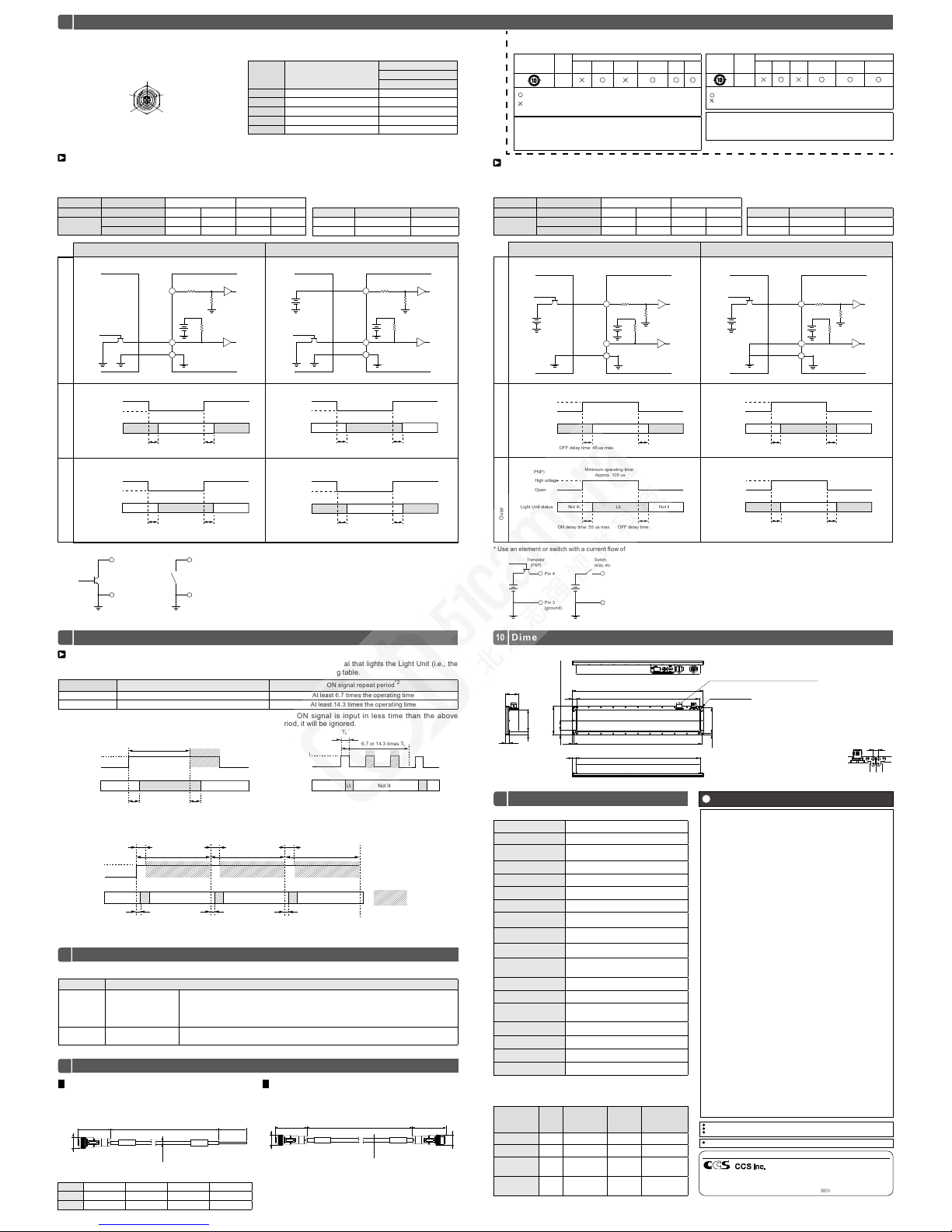
Signal fro m a Sinking Inpu t (NPN)
You can turn the light O N and OFF with a sign al input from the in put connector. Wit h these Light Unit s, you can use a
sinking inpu t (NPN) or a sourcing input (PN P).
Pin 4 Open
Constant Lighting Mode Connection Example
Pin 4 High Voltage
Overdrive Mode
Light Unit status
Pin 2 (NPN)
Lit. Lit.
Low voltage
Open
ON delay time: 55 us max.OFF delay time: 45 us max.
Not lit.
Minimum operating time:
Approx. 100 us
Light Unit status
Pin 2 (NPN)
Lit. Lit.
Low voltage
Open
ON delay time: 55 us max.OFF delay time: 45 us max.
Not lit.
Minimum operating time:
Approx. 100 us
Pin 2 (NPN)
Low voltage
Open
Light Unit status
Not lit. Not lit.
OFF delay time: 45 us max.
Lit.
ON delay time: 55 us max.
Minimum operating time:
Approx. 100 us
Pin 2 (NPN)
Low voltage
Open
Light Unit status
Not lit. Not lit.
OFF delay time: 45 us max.
Lit.
ON delay time: 55 us max.
Minimum operating time:
Approx. 100 us
LDLB Light Un itExternal Circuit
Pin 4
Pin 3
Pin 2
Transistor (NPN)
open collector
LDLB Light Un itExternal Circuit
5 VDC
24 VDC
Pin 4
Pin 3
Pin 2
Transistor (NPN)
open collector
5 VDC
**
Switch the si gnal input on pin 2 to turn the lig ht ON and OFF with a si gnal from a sinki ng input (NPN). Als o, you can input
a high voltage o n pin 4 to switch the logic for t urning the light ON and OFF.
Switch the si gnal input on pin 4 to turn the li ght ON and OFF with a signal fr om a sourcing input (PNP). Al so, you can input
a low voltage on p in 2 to switch the logic for tur ning the light ON and OFF.
* Use an elemen t or switch with a cur rent ow of approxima tely 1 mA in the extern al circuit.
Lo gic Ta ble
Refer to the foll owing table for the low and h igh voltages.
Logic switching
Pin 4 Open High voltage
Signal input Pin 2 (NPN) Open
Low voltage
Open
Low voltage
Operating
mode
Constant Lighting Mode
Lit. N ot lit. Not lit. Lit.
Overdrive Mode
Not lit. Lit. Lit. Not li t.
Logic switching
Pin 2 Open Low voltage
Signal input Pin 4 (PNP) Open
High voltage
Open
High voltage
Operating
mode
Constant Lighting Mode
Lit. N ot lit. Not lit. Lit.
Overdrive Mode
Not lit. Lit. Lit. Not li t.
Pin
Signal input status
Range
Pin 2 (NPN) Low vo ltage 0 to 1.1 VDC
Pin 4 High voltage
20.7 to 26.4 VD C
Pin
Signal input status
Range
Pin 2 Low voltag e 0 to 1.1 VDC
Pin 4 (PNP) High voltage
20.7 to 26.4 VD C
Transistor
(NPN)
Pin 2
Pin 3
(ground)
Switch,
relay, etc.
Pin 2
Pin 3
(ground)
Signal from a Sourcing Input (PNP)
Pin 2 Open
Constant Lighting Mode Connection Example
Pin 2 Low Voltage
Overdrive Mode
LDLB Light UnitExternal Circuit
5 VDC
24 VDC
Pin 4
Pin 3
Pin 2
Transistor (PNP)
open collector
*
LDLB Light Un itExternal Circuit
5 VDC
24 VDC
Pin 4
Pin 3
Pin 2
Transistor (PNP)
open collector
*
Pin 4 (PNP)
High voltage
Open
Lit.
Light Unit status
Lit.
OFF delay time: 45 us max.
Not lit.
ON delay time: 55 us max.
Minimum operating time:
Approx. 100 us
Pin 4 (PNP)
High voltage
Open
Lit.
Light Unit status
Lit.
OFF delay time: 45 us max.
Not lit.
ON delay time: 55 us max.
Minimum operating time:
Approx. 100 us
Light Unit status
Pin 4 (PNP)
Not lit. Not lit.
High voltage
Open
ON delay time: 55 us max. OFF delay time: 45 us max.
Lit.
Minimum operating time:
Approx. 100 us
Light Unit status
Pin 4 (PNP)
Not lit. Not lit.
High voltage
Open
ON delay time: 55 us max. OFF delay time: 45 us max.
Lit.
Minimum operating time:
Approx. 100 us
* Use an elemen t or switch with a cur rent ow of approxima tely 1 mA in the extern al circuit.
Logic Table
Refer to the foll owing table for the low and h igh voltages.
Pin 4
Pin 3
(ground)
Switch,
relay, etc.
Pin 4
Pin 3
(ground)
Transistor
(PNP)
Optional Products (Sold Separately)9
Error Displays
8
If an error oc curs, it will be shown on th e digital display on the ope rating panel.
Digital display Status
E1 Overdrive error
In Overdri ve Mode, the oper ating time or th e ON signal repe at period limi t was exceeded. Th is
error is sho wn on the digita l display for 3 sec onds. The mod e indicator on th e upper left of t he
digital dis play will ash cont inuously.
(The mo de indicator wi ll stop ashin g when you chan ge to Constant Lighting Mode or when you
cycle the pow er supply.)
E2 Overload error
An overload o ccurred, e.g., fou r or more Light Units we re connected.
Outputt ing light will be stopp ed and automatic re covery will be atte mpted after 3 seco nds.
Restric tions in Overd rive Mode
Depending o n the set light intens ity, the operating t ime and the repeat p eriod of the sig nal that lights th e Light Unit (i.e., the
ON signal) are r estricted. Input ON sig nals that meet the condit ions given in the following t able.
*1 If the ON signal exc eeds the above ope rating time (TL),
the light will b e turned OFF automatica lly.
*2 If the ON sig nal is input in less t ime than the above
period, it w ill be ignored.
Light intensity Operatin g time (TL)
*1
ON signal re peat period
*2
0 to 28 125 ms max. At least 6.7 tim es the operating ti me
29 to 99 10 ms max. At least 14.3 ti mes the operating t ime
If the ON signa l is input continuously, the li ght will repeatedly turn O N and OFF.
Light Unit
status
ON signal
6.7 or 14.3 times T
L
6.7 or 14.3 times TL6.7 or 14.3 times T
L
Not lit.
Lit.
Not lit.
Lit. Lit.
Not lit.
Not lit.
ON delay time: 55 us max.
T
L
: Operating time
(125 ms max. or 10 ms max.)
: Invalid ON signals
T
L
T
L
T
L
ON delay time: 55 us max.
ON delay time: 55 us max.
Common Specications
Specications by Model
Main Specifications
11
Input voltage (rating) 24 VDC
Input voltage (range) 22.8 to 26.4 VDC
Input current (rating)*
Constant li ghting mode: 1.3A max .
Overdrive m ode: 6A max.
Input connector M12 (5 pins, plug)
Output connector M12 (5 pins, socket)
Lighting mode Constant lightin g mode, overdrive mod e
Inrush current (max.) 6 A from a cold star t
Insulation withstand voltage
(input and output-case)
250 VAC for one min ute, cutoff curre nt: 10 mA,
500 VDC, 1MΩ m in.
Operating temperature
and humidity (indoors only)
Temperature: 0 to 40 °C, Humidity: 20% t o
85% (with no co ndensation)
Storage temperature
and humidity
Temperature: −20 to 6 0°C, Humidity: 20 %
to 85% (with no c ondensation)
Vibration resistance
Acceler ation: 19.6 m/s2, frequenc y: 10 to 55 Hz,
cycles: 3 minu tes,sweep cycle: for 1 h our
each in X, Y, and Z dire ctions
Shock
Acceler ation: 800 m/s2, Applica tion time: 11 ms,
Repetitio ns: 3 times each in 6 dire ctions
Cooling method Natural air cooling
CE Marking
Safety sta ndard: Conforms to E N62471
EMS standa rd: Conforms to EN610 00-6-2
EMI standar d: Conforms to EN610 00-6- 4
Environmental regulations
RoHS compliant
Case material Aluminum alloy, resin
Weight 500 g
Accessories Instruction Guide
Model
LED
color
Peak waveleng th /
Correlated color
temperature (typ.)
Power
consumption
(W) (max.)
Protective
structure
LDLB-300SW -N
White 6100 K 31
-
LDLB-300RD-N
Red 630 nm 24
-
LDLB-IP-30 0SW-N
White 6100 K 31
Conforms t o IP67
(JIS C 0920)
LDLB-IP-300RD-N
Red 630 nm 24
Conforms t o IP67
(JIS C 0920)
* Recommended ti ghtening torque: 0.7 N·m
*
* The dimensions shown on the left include
tolerance. If you mount two Light Units with
their short sides adjacent to each other, you
can separate the centers of the installation
holes by 8 mm to eliminate misregistration.
4 x Ø4.5
(For installation)
313
304
63
3.5
3.5
Sealing Cap: PROT-M12 (PHOENIX CONTACT)
(For LDLB- IP Series)
300 (発光面)
24 (Emitting surface)
10
320
70
11
Bottom view
Rear view
Top v iew
8
32
Side view
8
(0.6)
54
8
8
Headquarters
Address any product queries to the following address or to your nearest CCS representative.
* The power sup ply for daisy- chained Light U nits must provi de
sufci ent output for all of the L ight Units.
7
10
7
ON/OFF Inputs
DimensionsON/OFF Inputs (Continued)
Light Unit
status
ON signal
T
L
6.7 or 14.3 times T
L
Not lit.
Lit. Lit.
Not lit.
Not lit.
Light Unit
status
Not lit. Not lit.
ON signal
ON delay time: 55 us max. OFF delay time: 45 us max.
Lit.
T
L
Input Con nector (M12 Plug) Congur ation
5
4
1
3
2
Pin No. Signal
Cable
FECB-M12-5F Series
Wire color
1 24 VDC Brown
2 ON/OFF inp ut (NPN) White
3 Common ground Blue
4 ON/OFF i nput (PNP) B lack
5 An alog input (0 to 10 V) Gray
EXCEPT FOR THE EX PRESS WARRAN TIES STATED IN THIS DOCUME NT, CCS MAKES NO
ADDITIONA L WARRANTIES, EXPR ESS, IMPLIED, OR STATUTORY, AS TO ANY MATTER
WHATSOEVER. IN PAR TICULAR, ANY AND A LL WARRANTIES OF MERC HANTABILITY
OR FITNESS FOR PARTI CULAR PURPOS E ARE EXPRESSLY EXCLU DED.
EXCEPT AS EXPRE SSLY SET FORTH HEREIN, CCS MA KES NO WARRANTIES WI TH RESPECT TO THE PRODUCT S.
WARRANTY PE RIOD: TWO YEARS (ONE Y EAR FOR RADIANT QUAN TITY), STARTING
FROM CCS Inc. SHI PPING DATE.
CCS Inc. WILL REPAI R OR REPLACE THE PRODUCT F REE OF CHARGE IF IT SHOU LD
FAIL TO FUNCTION OR IF T HE RADIANT QUANTI TY OF THE PRODUCT SHOU LD DROP
TO 50% OR LESS OF ITS INI TIAL RADIAN T QUANTITY WITHI N THE SPECIFIED WARR ANTY PERIOD. IF EITH ER OF THESE CONDITI ONS OCCURS, PLEA SE TAKE THE PRODUCT
TO YOUR CCS SALES REPR ESENTATIVE.
WARRANTY TERMS
1 CCS Inc. W ILL REPAIR OR REPLACE TH E PRODUCT FREE OF CHA RGE IF IT SHOULD
FAIL TO FUNCTION UN DER USE ON OUR SPECIFIED CO NDITION IN ACCORDANC E
WITH THE INSTRU CTION GUIDE AND OTHER W RITTEN CAUTIONS DU RING THE INDICATED WARRANT Y PERIOD OF TWO YE ARS.
2 CCS Inc. WILL REPAI R OR REPLACE THE PRO DUCT FREE OF CHARG E IF ITS RADIANT
QUANTITY SHO ULD DROP TO 50% OR LESS OF ITS IN ITIAL RADIANT QU ANTITY UNDER USE ON OUR SPECI FIED CONDITION IN AC CORDANCE WITH TH E INSTRUCTION
GUIDE AND OTHER W RITTEN CAUTIONS DUR ING THE INDICATED WARRA NTY PERIOD OF ONE YEAR .
3 CCS Inc. WILL CHA RGE A REPAIR FEE UNDE R THE FOLLOWING CON DITIONS:
1) IF THE PRODUCT HAS BE EN SUBJECTED TO MISUSE, UN AUTHORIZED REPAIRS,
OR MODIFICATION FRO M ITS ORIGINAL D ESIGN.
2)
IF THE PRODUCT HA S BEEN DAMAGED FROM IMPACTS DU E TO INAPPROPRIATE HAN-
DLING.
3) IF DAMAGE TO THE PROD UCT RESULTS FROM EXTERNAL CAU SES INCLUDING
ACCIDENTS, FIRE , POLLUTION, RIOTS, COMM UNICATION FAILURES, EARTH QUAKES, THUND ERSTORMS, WIND AND FLOO D DAMAGE, OR ANY OTHER ACT OF
P
ROVIDENCE, OR FRO M ANY EXTRAO RDINARY CONDIT IONS SUCH AS ELECTRI CAL
SURGES, WATER LEAK AGE, CONDENSATIO N, OR THE USE OF CHEM ICALS.
4) IF THE DAMAGE RESU LTS FROM CONNECTION TO AN Y Control Unit OR TO AN Y EQUIPMENT
WHICH CCS Inc. DO ES NOT MANUFACTURE O R DOES NOT SPECIFY FO R USE.
4
CCS ASSUMES NO LI ABILITY FOR ANY PURCH ASER’S SECONDARY DAMAG E (DAMAGE
OF
EQUIPMENT, LOSS OF OPP ORTUNITIES, LOSS OF PROFITS , ETC.) OR ANY OTHER
DAMAGE RESULTING FRO M A FAILURE OF OUR PROD UCT.
THIS WARRAN TY INFORMATION PROVI DES THE SCOPE OF CCS 'S PRODUCT WARRA NTY WITHIN THE S PECIFIED PERIOD, AN D DOES NOT INDICATE OR IMP LY ANY FURTHER
GUARANTEE B EYOND THE WARRA NTY TERMS.
CONTACT CCS FOR INQUI RIES OR INFORMATION ON REPAI RS TO THE PRODUCT AFTER THE EXPIR ATION OF THE WARRA NTY.
NOTE: THE RADI ANT QUANTITY REFERS TO TH E WATTAGE OF PHYSICAL ENERGY RADI ATED
FROM AN LED. IT REFERS TO TH E RADIATION LUMINOSIT Y OF THE LED MEASURED
UNDER CONDIT IONS SPECIFIED BY CCS OR TH E RADIATION ILLUMIN ATION OF THE LED
UNDER SPECIFIED I RRADIATION CON DITIONS. CCS SPEC IFIES THE RADIA NT QUANTITY
FOR EACH LED LIGHT B ECAUSE THE MEASUREME NT AND IRRADIATION CO NDITIONS
VARY FROM THE FORM, T HE APPLICATION AND THE IRR ADIATION WAVELENGTH.
Warranty Information
Copyright© 2016 CCS Inc. All Rights Reserved.
Descript ions in this instr uction guide are bas ed on informatio n available as of July 2016. K Z06922-T001- 003
Shimodachiuri-agaru, Karasuma-dori, Kamigyo-ku,Kyoto 602-8011 Japan
E-mail : [email protected]
Phone : +81-75-415- 8284 Fax : +81-75- 415-8278
Use our website to nd y our nearest CCS rep resentative.
http://www.ccs-grp.com/mvad
Contents of this In struction Guid e may be changed witho ut prior notice.
Illustrations u sed in this Instruc tion Guide may dif fer from actual pro ducts.
CCS maintains th e copyright on this I nstruction Gui de. Unauthorized t ransfer or reprod uction is strict ly prohibited.
Instruction G uide and Dimensio nal Diagrams in PDF o r CAD can be download ed from the CCS webs ite. http://ww w.ccs-grp.co m
Information Required for China RoHS Directive
环保
使用期限
产品
有害物质的名称及含量
铅
(Pb)汞(Hg)镉(Cd)
六价铬
(Cr( VI))
多溴联苯
(PBB)
多溴二苯醚
(PBDE)
LED 照明
( 本表格依据S J/T11364 的规定编制。)
:
表示该有毒有害物质在该部件所有均质材料中的含量均在 GB/T26572 标准规定的限量要求以下。
:
表示该有毒有害物质至少在该部件的某一均质材料中的含量超出 GB/T26572 标准规定的限量要求。
( 注)铅和镉中的“×”,因欧洲 RoHS没限定,故用“○”表示。
Usage deadline for environmental protection
The number use d in this logo is based on “ Management Meth ods for Restrictin g Hazardous Subst ances Used
in Electric a nd Electronic Products ” and related regulations f rom People’s Republic of China . It shows the
product usage duration in years for environmental protection. After nishing a product usage, the product
needs to be re- used or discarded ap propriately follow ing local law and regul ations, complyin g with safety and
usage caution.
Usage Deadline
for Environmental
Protection
Product
name
Names and contents of hazardous substances
Lead
(Pb)
Mercury
(Hg)
Cadmium
(Cd)
Hexavalent
chromium (Cr(VI))
PBB PBDE
LED
Lights
(This table is ma de in compliance w ith SJ/T11364 regulati ons.)
: Indicates that th is toxic or hazardous substa nces contained in all the ho mogeneous
materials for thi s part, accordi ng to GB/T2657 2 is within the limit re quirement.
: Indicates that th is toxic or hazardous s ubstance contai ned in all the homogen eous materials
for this part, ac cording to GB/ T26572, is over the lim it requirement.
*Lead and cadmiu m are excluded in EU RoHS.
Names and contents of hazardous substances
产品中有害物质的名称及含 量
环保使用期限
此标志的数字是根据中华人民共和国电器电子产品有害物质限制使用管理办法以及有关标准等,表示该产品的环
保使用期限的年数。
遵守产品的安全和使用上的注意,在产品使用后采 取适当的方法根据各地法律,规定,回收再利用或进
行废弃处理。
Ø14.8
44 n x 1000 50
(Ø5 .1)
(n=1, 2, 3, 5)
(Unit: mm)
(Unit: mm)
Light Unit (in put connector)
(Socket)
Input connector
(Socket)
Output connector
(Plu g)
Flying leads
(5 wires, AWG22)
Ø14.8
(Ø5 .1)
Ø14.8
44 600 46.8
Input Cable Link Cable
Model: FECB- n-M12-5F Model: FECB- 0.6-M12-5M-5F
This cable i s used to supply power to th e Light Unit and to input si gnals to contr ol the light intensi ty and turn the light O N and OFF.
Use this cable for daisy-chain connections.
Select the required cable length.
Weight: 50 g ma x.
Model
FECB-1-M12-5F FECB-2-M12-5F FECB-3-M12-5F FECB-5-M12-5F
Length 1 m 2 m 3 m
5 m
Weight 55 g ma x. 90g max. 130g max. 210g max.
 Loading...