

Page 1
2015
iNetVu New Generation Ka-Band
Troubleshooting Guide
Revision 3.0
C-COM Satellite Systems
5/25/2015
Page 2
iNetVu New Gen Troubleshooting Guide
Page 2 of 68
Copyright © 2010. All rights reserved. C-COM Satellite Systems Inc.
This document contains information, which is protected by copyright. All rights reserved.
Reproduction, adaptation, or translation without prior written permission is prohibited, except
as followed under the copy r i g ht law s.
Both the iNetVu™ and C-COM names and logos are registered trademarks of C-COM
Satellite Systems Inc.
®
Intel
Pentium is a registered trademark of Intel Corporation. Microsoft, Windows, Windows
NT and MapPoint are registered trademarks of Microsoft Corporation.
All other product names mentioned in this manual may be trademarks or registered
trademarks of their respective companies and are the sole property of their respective
manufacturers.
C-COM Satellite Systems Inc.
Page 3

iNetVu New Gen Troubleshooting Guide
Page 3 of 68
FCC and INDUSTRY CANADA INFORMATION TO THE USER:
The FCC and Industry Canada have imposed the following conditions when operating,
installing and deploying iNetVu™ Mobile Earth Stations and is mandatory for all installations
made within the Continental United States and Canada as well as Hawaii, Alaska, Puerto
Rico, the U.S. Virgin Islands and other U.S. Territories. The FCC requires that a certified
installer perform the installation. It is also strongly recommended that a qualified professional
RV dealer/installer mount the system on your vehicle. These conditions are also required by
C-COM for all other installed locations.
All iNetVu™ Mobile earth station installers must be C-COM Certified, and must have
specifically acknowledged the requirements for iNetVu™ Mobile installations, which are as
follows:
“Installation” is the physical mounting and wiring of the Satellite provider’s earth station
on a vehicle or other stationary site in order to prepare for correct operation. Only Cer tified CCOM iNetVu installers may perform the installation and removal of an iNetVu™ Mobile
system.
“Deployment” means the raising, pointing and orienting of the earth station to the
communicating satellite, every time it is raised from a stowed position for use. The
deployment of an iNetVu™ Mobile system must only be done by a trained installer or by a
consumer using the deployment software.
Installers shall install the iNetVu™ systems only in locations that are not readily accessible to
children and in a manner that prevents human exposure to pot enti al radiation hazards.
For large vehicles with roof mounts, the height of the bottom lip of the earth station when fully
deployed must be at least six feet above the ground at all times, or six feet above a
surrounding surface which a person may easily access.
If a roof access ladder or any other means of access to the roof is installed on the
vehicle, then the ladder or access must be blocked by a suitable rope or other barrier while
the earth station is deployed or in operation. The installer must provide this rope or barrier
directly to the end user at the time of installation and advise the user to use it at all times
when the earth station is deployed or in operation. Warning signs shall also be provided by
the installer to the end user to be posted on the rope or other barrier warning all persons not
to attempt to access the roof of the vehicle while the earth station is deployed or in operation.
Warning signs shall be posted at prominent locations on the earth station informing all
persons of the danger of harmful radiation from the earth station while it is deployed or while
in operation.
The iNetVu™ Mobile system may only be operated when the vehicle is stationary.
The installer must inform the end user that the vehicle must be stabilized during the
transmission, to prevent movement of the vehicle for any reason, including movement of
persons on or off the vehicle, or high winds. The installer shall advise the end user how to
appropriately stabilize their vehicle.
Installers shall be liable for all damages if they fail to comply with the above mandatory
conditions. This includes, but is not limited to damages caused by improper installation or
due to the failure to provide required information to the end user.
C-COM Satellite Systems Inc.
Page 4

iNetVu New Gen Troubleshooting Guide
Page 4 of 68
Installers and end users will be deemed directly liable for any damages resulting from either
of their failure to comply with the above rules. These rules are meant to ensure that
extraordinary precautions and measures are used to prevent satellite interference or
exposure to harmful radiation. C-COM reserves the rights to immediately suspend without
liability or previous notice the operation of the earth station upon detection of a deviation
from its installation or operational requirements until the deviation is corrected. In addition, CCOM reserves the right to suspend or cancel the Installer Certificate of any installer that has
not fully complied with these installation requirements.
Further, the installer and end user may be directly liable for any damages resulting
from any change undertake n by either of them. Including but not limited to, any modification of
any part of the hardware, software, specific operational frequencies, the authorized satellite,
or the size or other characteristics of the earth station supplied to them by C-COM or CCOM’s authorized representatives.
Note 1:
This equipment has been tested and found to comply with the limits for a Class B digital
device, pursuant to Part 15 of FCC rules. These limits are designed to provide reasonable
protection against harmful interference when the equipment is operated in a residential
installation. This equipment generates, uses, and can radiate radio frequency energy and, if
not installed and used in accordance with this instruction manual, may cause harmful
interference with radio communications. However, there is no guarantee that interference will
not occur in a particular installation. If this equipment does cause harmful interference to
radio or television reception, which can be determined by turning the equipment off and on,
the user is encouraged to try to correct the interference by one or more of the following
measures:
Reorient or relocate the receiving antenna.
Increase the separation between the equipment and receiver.
Connect the equipment into an outlet on a circuit different from that to which the receiver is
connected.
Consult the dealer or an experienced radio / TV technician for help.
Note 2:
This Class B digital apparatus complies with Canadian ICES-003.
C-COM Satellite Systems Inc.
Page 5

iNetVu New Gen Troubleshooting Guide
Page 5 of 68
C-Com Satellite Systems Global Headquarters
Phone: +1-613-745-4110 OPT3
Toll Free: 1-877-463-8886 OPT3
Monday – Friday, 8:30am – 6:00pm EST
Monday – Friday, 6:00pm – 9:00pm EST
Weekends an d Canadian Hol idays
2574 Sheffield Road
Ottawa, O nt ar i o , Canada
K1B 3V7
Phone: +1-613-745-4110
Fax: +1-613-745-7144
General In q uiries:
Dealer Information:
Support Services:
After Hours Support:
Tel: 1-613-656-3723
Toll Free: 1-800-233-0218
8:30am – 9:00pm EST
C-COM Satellite Systems Inc.
Page 6

iNetVu New Gen Troubleshooting Guide
Page 6 of 68
Table of Contents
INTRODUCTION ...................................................................................................................... 8
7000 CONTROLLER SOFTWARE & FIRMWARE UPGRADE ............................................... 9
UNINSTALLING THE CURRENT SOFTWARE ................................................................................. 10
INSTALLING THE 7000 SERIES CONTROLLER SOFTWARE VERSION 7.5.8 ..................................... 11
THE INETVU SETUP WIZARD .................................................................................................... 14
VERIFYING THE UPGRADE COMPLETED SUCCESSFULLY ............................................................. 19
JAM ERRORS ........................................................................................................................ 20
ERROR 0X9006 - EL JAM ERROR ............................................................................................. 21
1. If the Mobile Platform doesn’t physically move ........................................................... 21
2. If the Mobile Platform physically moves but the angle doesn’t change ....................... 23
ERROR 0X9007 - AZ JAM ERROR ............................................................................................ 26
1. If the Mobile Platform doesn’t physically move ........................................................... 26
2. If the Mobile Platform physically moves but the angle doesn’t change ....................... 28
OVER CURRENT PROTECTION ........................................................................................... 31
0X9003 --- EL OVER CURRENT ................................................................................................ 32
0X9004 --- AZ OVER CURRENT ................................................................................................ 32
SENSOR ERRORS ................................................................................................................ 33
ERROR 0X8911 - SENSOR ERRORS ....................................................................................... 34
ENSOR CABLE AND INTERNAL HARNESS CONTINUITY TEST FOR EL TILT .................................... 35
S
S
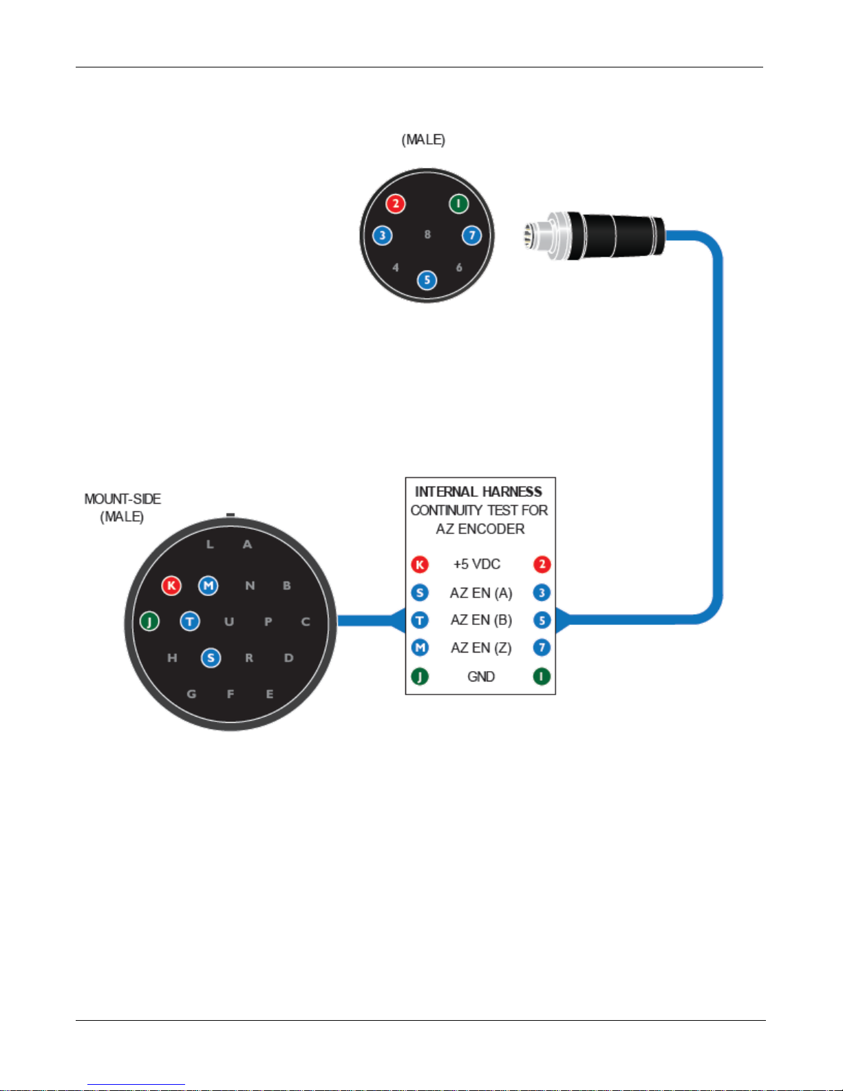
ENSOR CABLE AND INTERNAL HARNESS CONTINUITY TEST FOR AZ ENCODER ........................... 37
COMPASS .............................................................................................................................. 39
COMPASS VALUE IS NOT ACCURATE .......................................................................................... 40
RESTORING THE COMPASS ...................................................................................................... 41
GPS ........................................................................................................................................ 42
ERROR 0X8914 - GPS FAILED .............................................................................................. 43
STOW ..................................................................................................................................... 45
ERROR 0XA003 / 0XA006 - STOW FAILED .............................................................................. 46
Step 1: Testing the Limit Switch. ........................................................................................ 47
Step 2: Testing the Wiring Har ness. ................................................................................... 48
Step 3: Testing the Sensor Cable. ..................................................................................... 48
Step 4: Testing the 7000 Controller. ................................................................................... 49
ERROR 0X8010 - CAN'T STOW (EL LIMIT) .............................................................................. 50
Step 1: Testing the Limit Switch. ........................................................................................ 51
Step 2: Testing the Wiring Har ness. ................................................................................... 51
Step 3: Testing the Sensor Cable. ..................................................................................... 52
Step 4: Testing the 7000 Controller. ................................................................................... 53
C-COM Satellite Systems Inc.
Page 7

iNetVu New Gen Troubleshooting Guide
Page 7 of 68
RF SIGNAL LOSS .................................................................................................................. 54
ERROR 0X8915 - RF IS TOO LOW OR TRIA IS NOT BEEPING ........................................... 55
RF Signal Not Being Detected (Single IFL Cable Setup) ................................................... 56
RF Signal Not Being Detected (Dual IFL Cable Setup) ...................................................... 58
MODEM .................................................................................................................................. 61
ERROR 0X8801 - NO MODEM COMMUNICATION ...................................................................... 62
CANNOT FIND SATELLITE ................................................................................................... 64
HOW THE INETVU SEARCH METHOD WORKS ............................................................................ 67
APPENDIX 1: FASTENER TORQUE TABLE ....................................................................... 68
C-COM Satellite Systems Inc.
Page 8

iNetVu New Gen Troubleshooting Guide
Page 8 of 68
INTRODUCTION
About This Manual
This manual explains how to troubleshoot common errors on the iNetVu™ Mobile System 755
and 985. An electronic version of this manual is available on the C-COM FTP and Knowledge
Base.
C-COM Satellite Systems Inc.
Page 9
iNetVu New Gen Troubleshooting Guide
Page 9 of 68
Minimum Requirements to run IMS Software
IMS Version
RAM
Processor Clock
Disk Space
Microsoft .NET Version
.
7000 CONTROLLER SOFTWARE & FIRMWARE UPGRADE
Quick Tip: The software and firmware versions must match for normal operation.
7.5.8 + 1 GB 2.0 GHZ 100 Megs Of Free Space
NET Framework 3.5
C-COM Satellite Systems Inc.
Page 10
iNetVu New Gen Troubleshooting Guide
Page 10 of 68
Uninstalling the Current Software
Note: This method describes the steps for upgrading to 7.5.8
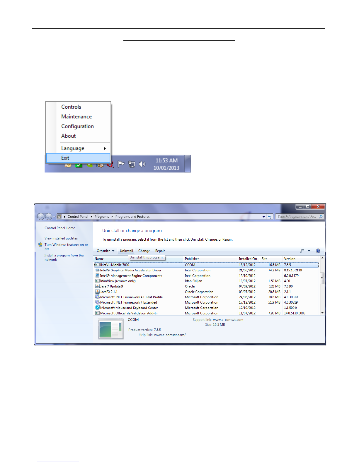
1. Ensure the iNetVu software is not running. If it is, right click the icon on the bottom right of the
screen and exit. As shown below.
2. Go to the Windows Control Panel and uninstall the iNetVu Mobile 7000 software.
C-COM Satellite Systems Inc.
Page 11
iNetVu New Gen Troubleshooting Guide
Page 11 of 68
Installing the 7000 Series Controller Software Version 7.5.8
Please Note: Do not connect the Controller via USB until the drivers and software have been installed
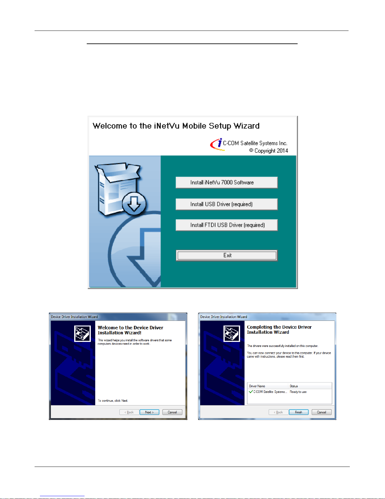
1. If you are installing from the USB flash drive or have downloaded from the C-COM FTP, run
the iNetVu7000Setup.exe file.
2. Install both the USB and FTDI USB Drivers.
3. Install the USB Driver and close when completed.
C-COM Satellite Systems Inc.
Page 12
iNetVu New Gen Troubleshooting Guide
Page 12 of 68
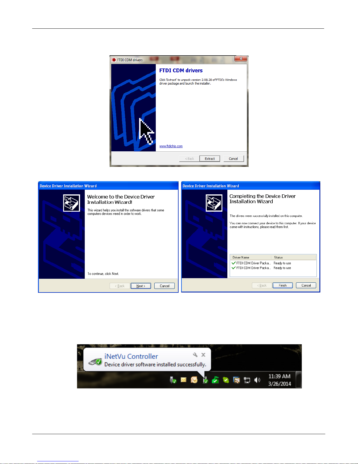
4. Install the FTDI USB Driver and close when completed.
Click “Extract”
Click “Next” Click “Finish”
5. Install the iNetVu 7000 Software and close when completed.
6. Connect the Controller using the provided USB cable. Windows Vista and 7+ users, the
drivers should install automatically without any further user action.
C-COM Satellite Systems Inc.
Page 13
iNetVu New Gen Troubleshooting Guide
Page 13 of 68
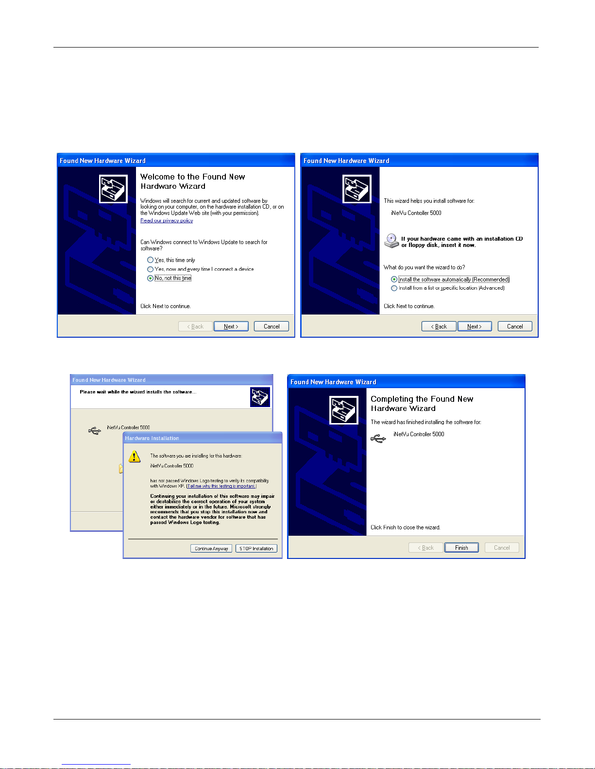
7. Windows XP users will have to follow the new hardware wizard and let windows automatically
install the drivers.
Select “No, not this time” Select “Install the software automatically”
Click “Continue Anyway” Click “Finish”
8. You have successfully installed the 7000 iNetVu Drivers and Software. Exit the setup wizard.
9. You can now run the iNetVu Mobile 7000 software from the shortcut on your desktop.
10. If this is an upgrade we must update the Controller Firmware. Pease use the setup wizard on
the next page to continue.
C-COM Satellite Systems Inc.
Page 14
iNetVu New Gen Troubleshooting Guide
Page 14 of 68
The iNetVu Setup Wizard
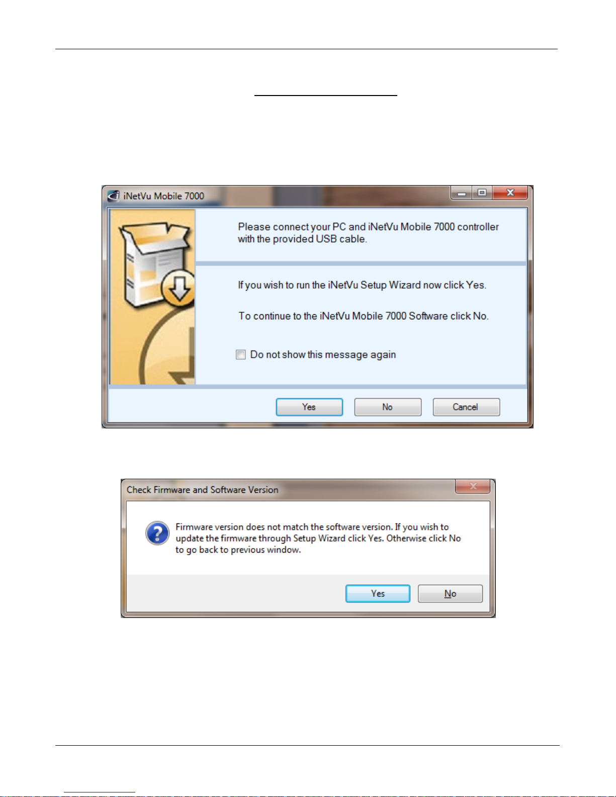
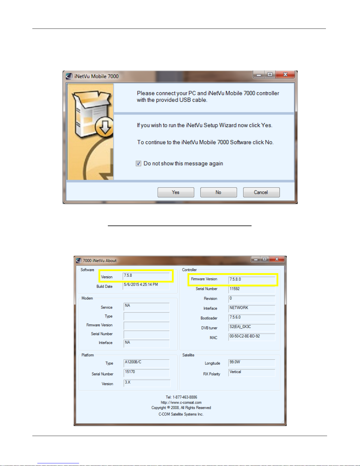
1. The first screen you will see is the new iNetVu Setup Wizard. You can choose to continue
using the wizard or click NO to proceed to the iNetVu Mobile 7000 software.
NOTE: It is recommended that you continue to the iNetVu Setup Wizard and confirm all
required information is correct.
2. If the controller firmware does not match you will be prompted to update.
C-COM Satellite Systems Inc.
Page 15
iNetVu New Gen Troubleshooting Guide
Page 15 of 68
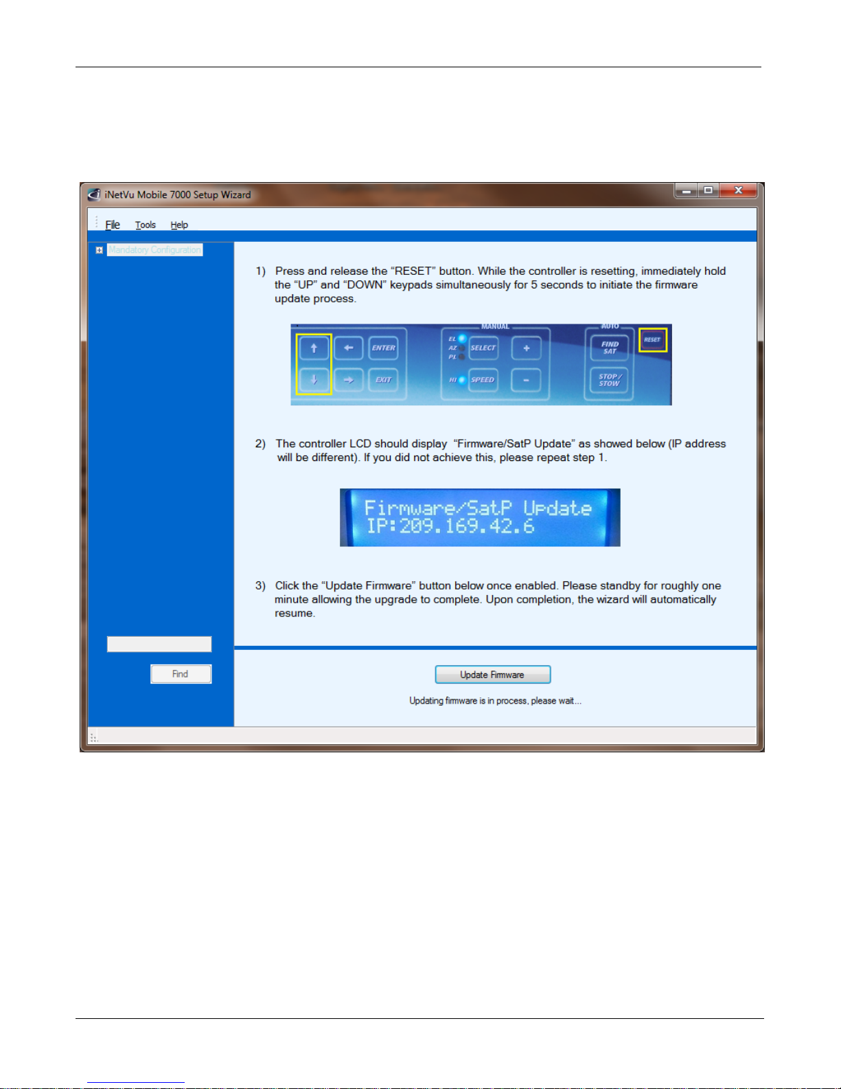
3. Follow the on screen instructions to update the controller firmware. Once complete the wizard
will resume.
C-COM Satellite Systems Inc.
Page 16
iNetVu New Gen Troubleshooting Guide
Page 16 of 68
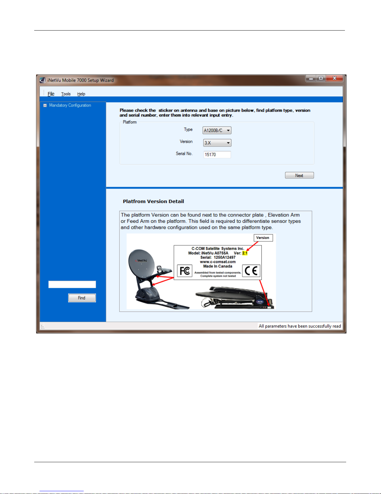
4. Configure the Platform Type. If no changes are needed press “Next” to continue.
C-COM Satellite Systems Inc.
Page 17
iNetVu New Gen Troubleshooting Guide
Page 17 of 68
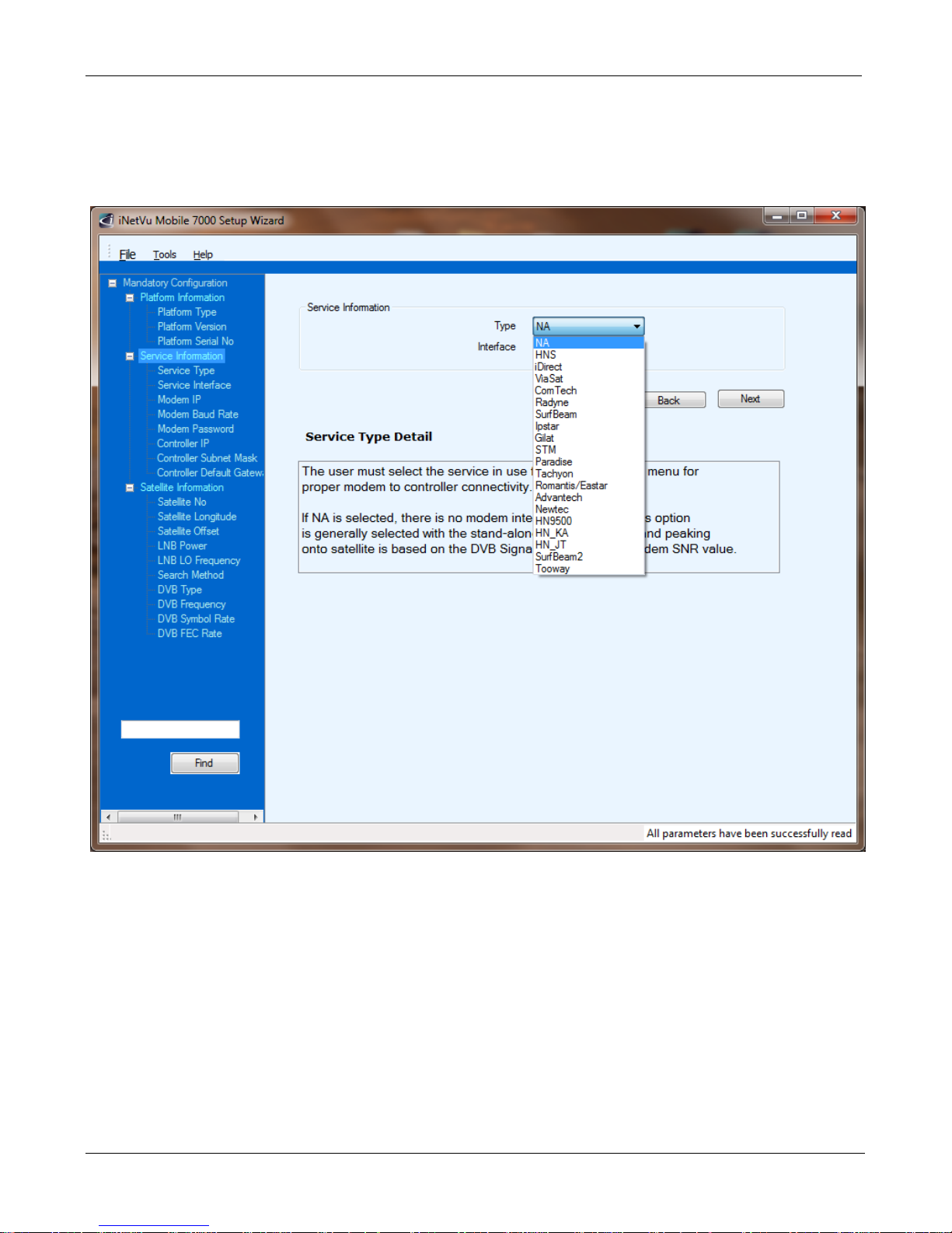
5. Configure the Service Information (Modem). If no Modem is to be used please select NA. If no
changes are needed press “Next” to continue.
C-COM Satellite Systems Inc.
Page 18
iNetVu New Gen Troubleshooting Guide
Page 18 of 68
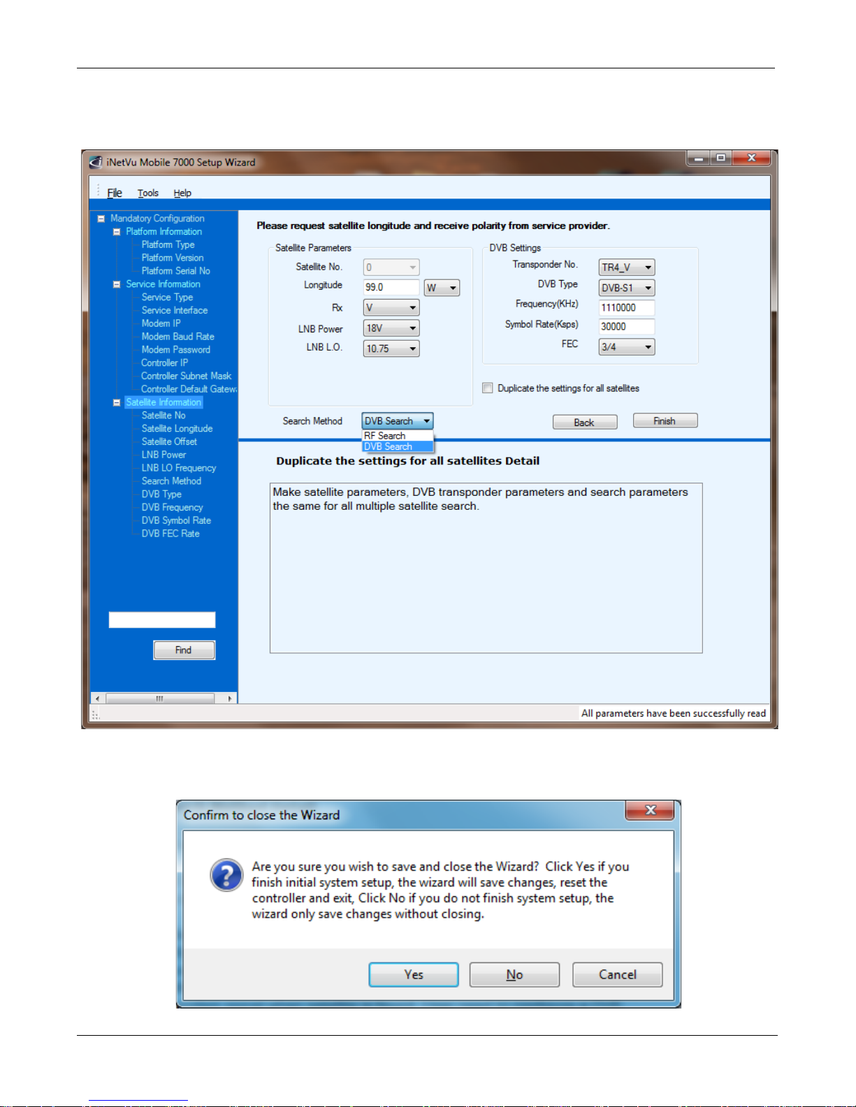
6. Configure the Satellite Parameters. If no DVB Carrier is to be used you must select RF Search.
If no changes are needed press “Next” to continue.
7. Once complete Press Yes to continue or No to go back and make changes.
C-COM Satellite Systems Inc.
Page 19
iNetVu New Gen Troubleshooting Guide
Page 19 of 68
8. Now that the controller has been configured, launch the software again selecting NO to
continue to the iNetVu Mobile 7000 Controls Screen. You may also wish to stop this prompt
from reappearing.
Verifying the Upgrade Completed Successfully
9. From the Controls screen, right click and select “About”. Verify both Software and Firmware
versions are identical.
C-COM Satellite Systems Inc.
Page 20

iNetVu New Gen Troubleshooting Guide
Page 20 of 68
JAM ERRORS
Quick Tip: The key to troubleshooting a Jam Error is to determine whether this is a Sensor or
Mechanical failure.
C-COM Satellite Systems Inc.
Page 21
iNetVu New Gen Troubleshooting Guide
Page 21 of 68
DO NOT OPEN
Error 0x9006 - EL Jam Error
1. If the Mobile Platform doesn’t physically move
Possible Causes:
• 7000 Controller
• 15 Amp Fuse
• Motor Cable
• Internal Wiring Harness
• Elevation Motor or Belt
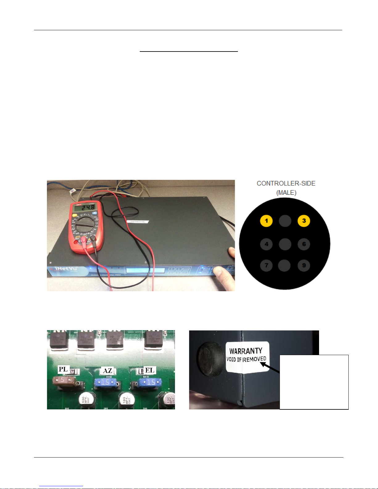
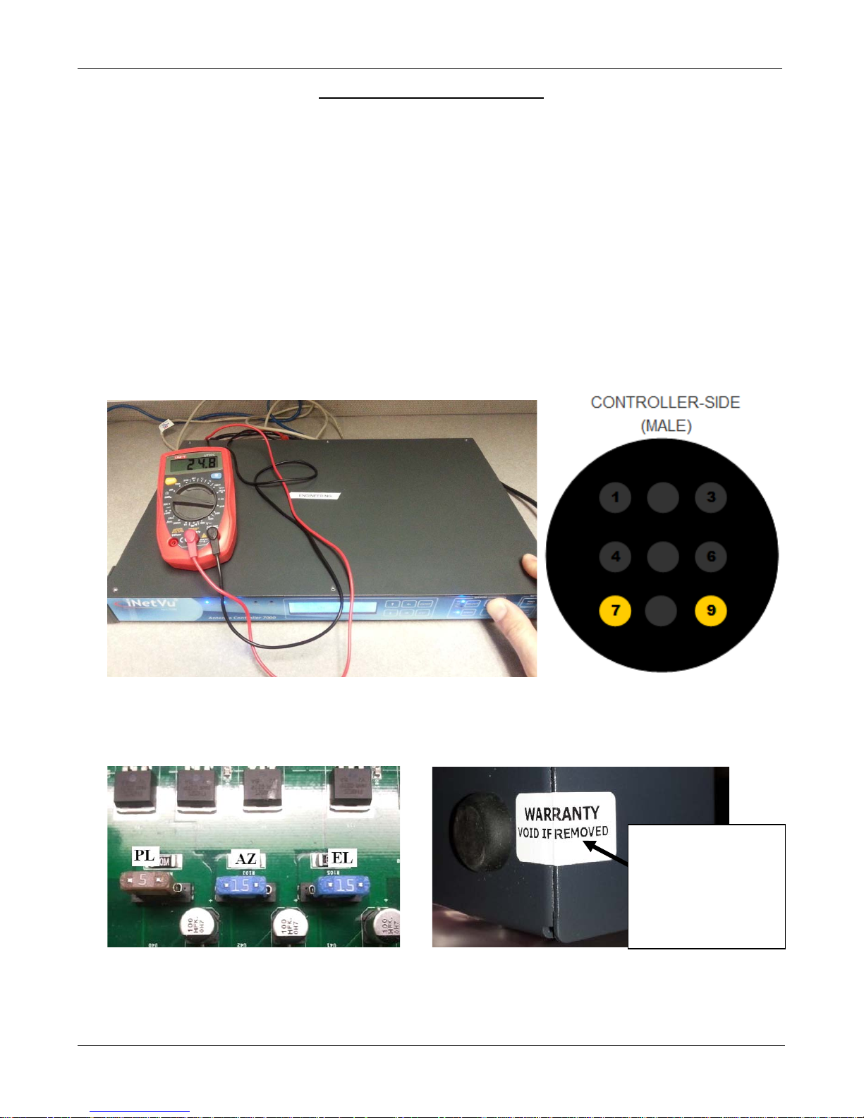
a. Verify if 7000 Controller is outputting 24VDC. Disconnect the motor cable from the back of the
controller, place the volt meter leads on pins 1 and 3 of the controller. Using the 7000 controllers
front panel, select Elevation with HI SPEED on and hold +. Are you getting 24VDC?
b. If no voltage is shown, please turn off the controller and verify the 15A fuse has not blown. If the
fuse is blown replace it and try again. If the fuse is not blown, contact C-Com Technical Support for
further assistance.
Warning High Voltage: Always remove power from the 7000 Controller prior to removing fuse.
Failing to do so can result in personal injury or damage to the controller.
C-COM Satellite Systems Inc.
Contact C-COM
before opening if
your controller has
this Seal.
Page 22
iNetVu New Gen Troubleshooting Guide
Page 22 of 68
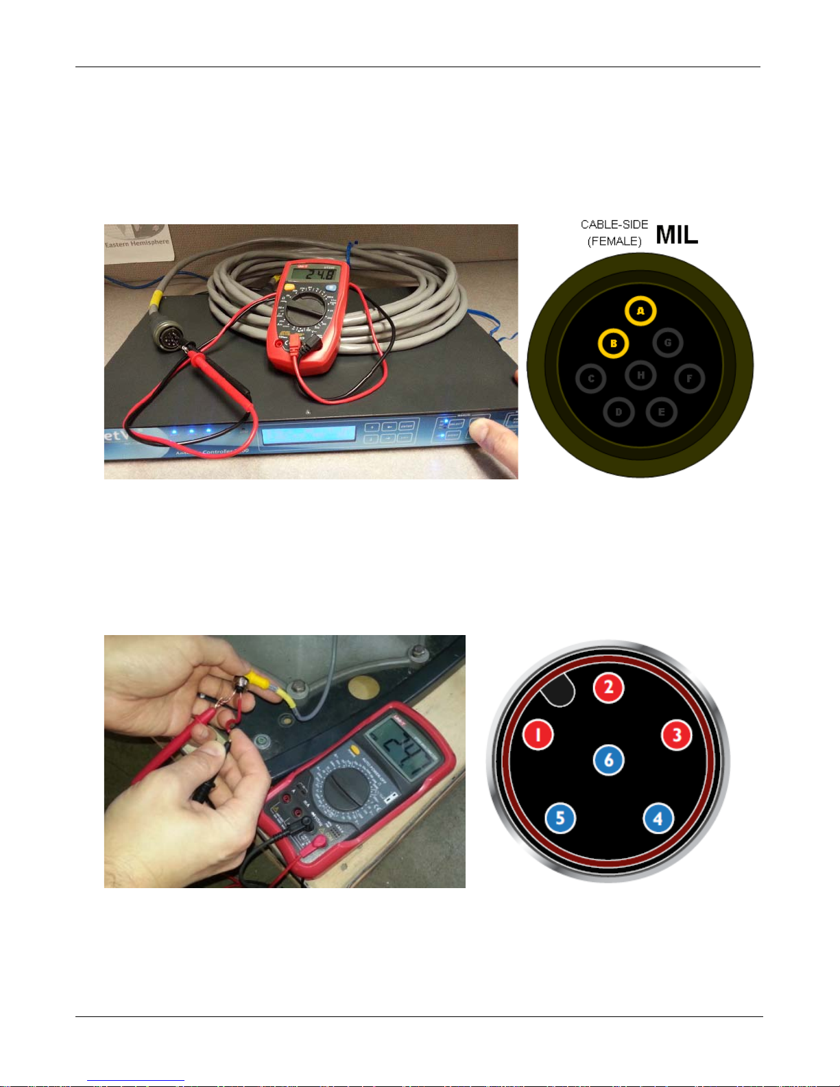
c. If we are getting voltage from the Controller, we will need to test voltage on the motor cable.
Reconnect the motor cable to the controller and disconnect it from the platform. Place the volt
meter leads on pins A and B of the motor cable. Using the 7000 controllers front panel, select
Elevation with HI SPEED on and hold +. Are you getting 24VDC? If no voltage is shown, it
concludes the motor cable needs to be replaced. Contact C-Com Technical Support for further
assistance.
d. If we are getting voltage on the Motor Cable, reconnect the cable and now we will need to test
voltage on the internal wiring harness. Disconnect the connector going into the Elevation Motor.
Place the volt meter leads on the power connector leading to the wiring harness. Using the 7000
controllers front panel, select Elevation with HI SPEED on and hold +. Test in this combination
1+4, 2+5 and 3+6. Are you getting 24VDC in all combinations? If no voltage is shown, it concludes
the internal wiring harness needs to be replaced. Contact C-Com Technical Support for further
assistance.
e. If we are getting voltage from the Wiring Harness, the Elevation Motor may have failed. Please
Contact C-COM Technical Support for further instructions.
C-COM Satellite Systems Inc.
Page 23
iNetVu New Gen Troubleshooting Guide
Page 23 of 68
2. If the Mobile Platform physically moves but the angle doesn’t change
Possible Causes:
• Elevation Tilt Sensor
• Sensor Cable
• Internal Wiring Harness
• 7000 Controller
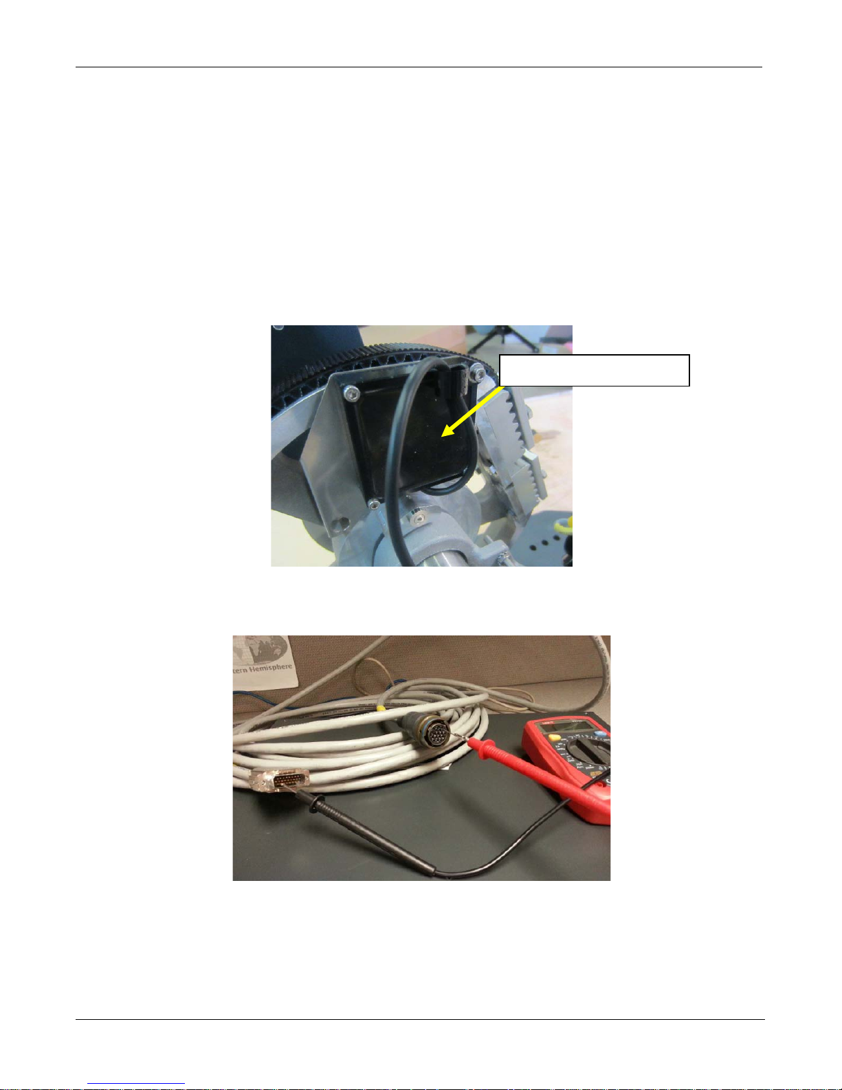
a. Please ensure the Sensor Cable is securely connected to the 7000 Controller and Platform.
Reseat the Sensor Cable and the Elevation Tilt Sensor cable. If the issue persists continue to the
next step.
Elevation Tilt Sensor
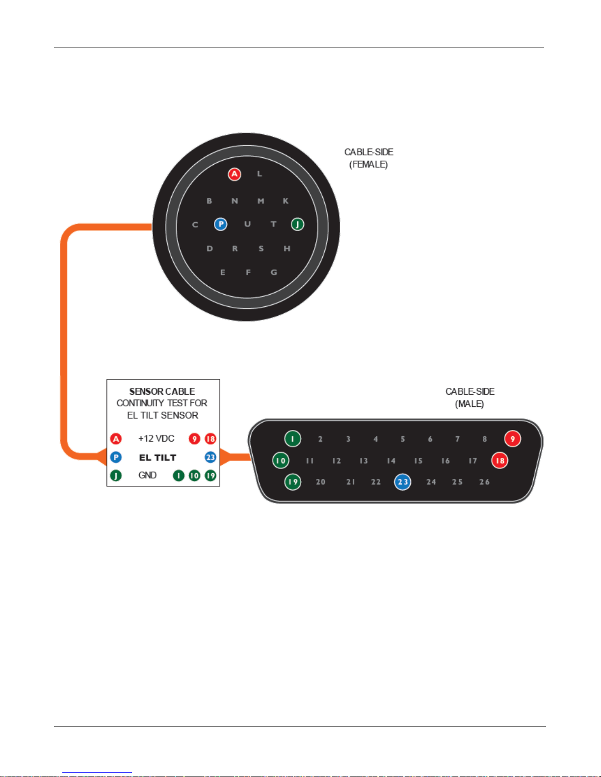
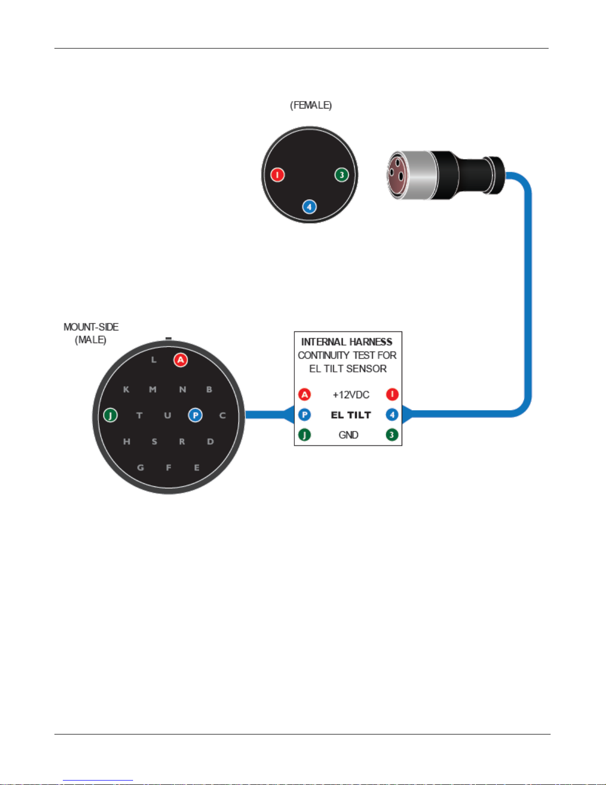
b. Use the Elevation Tilt Sensor Circuit Diagram on the following page to confirm continuity of the
cabling. Set the voltmeter to beeper or continuity mode.
c. If either the sensor cable or internal harness fails continuity please Contact C-COM Technical
Support for further instructions.
d. If the cabling passes continuity, this will conclude the issue is the Elevation Tilt Sensor. Please
Contact C-COM Technical Support for further instructions.
C-COM Satellite Systems Inc.
Page 24
iNetVu New Gen Troubleshooting Guide
Page 24 of 68
Sensor Cable and Internal Harness Continuity Test for EL Tilt
Sensor Cable
C-COM Satellite Systems Inc.
Page 25
iNetVu New Gen Troubleshooting Guide
Page 25 of 68
Internal Harness
C-COM Satellite Systems Inc.
Page 26
iNetVu New Gen Troubleshooting Guide
Page 26 of 68
DO NOT OPEN
Error 0x9007 - AZ Jam Error
1. If the Mobile Platform doesn’t physically move
Possible Causes:
• 7000 Controller
• 15 Amp Fuse
• Motor Cable
• Internal Wiring Harness
• Azimuth Motor or Belt
a. Verify if 7000 Controller is outputting 24VDC. Disconnect the Motor cable from the back of the
controller, place the volt meter leads on pins 7 and 9 of the controller. Using the 7000 controllers
front panel, select Azimuth with HI SPEED ON and hold +. Are you getting 24VDC?
b. If no voltage is shown, please turn off the controller and verify the 15A fuse has not blown. If the
fuse is blown replace it and try again. If the fuse is not blown, contact C-Com Technical Support for
further assistance.
Warning High Voltage: Always remove power from the 7000 Controller prior to removing fuse.
Failing to do so can result in personal injury or damage to the controller.
C-COM Satellite Systems Inc.
Contact C-COM
before opening if
your controller has
this Seal.
Page 27
iNetVu New Gen Troubleshooting Guide
Page 27 of 68
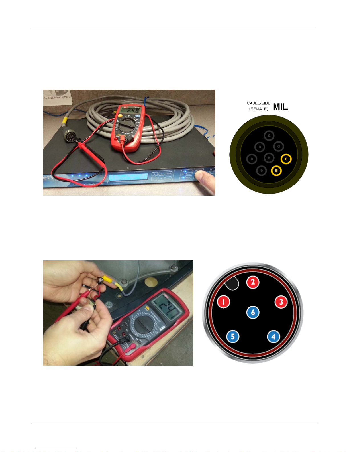
c. If we are getting voltage from the Controller, we will need to test voltage on the Motor cable.
Reconnect the Motor cable to the controller. Disconnect the Motor cable from the Platform. Place
the volt meter leads on pins F and E of the Motor cable. Using the 7000 controllers front panel,
select Azimuth with HI SPEED ON and hold +. Are you getting 24VDC? If no voltage is shown, it
concludes the Motor cable needs to be replaced. Contact C-Com Technical Support for further
assistance.
d. If we are getting voltage from the Motor Cable, reconnect the Motor cable to the Platform. Now
we will need to test voltage on the wiring harness. Disconnect the connector going into the
Azimuth Motor. Place the volt meter leads on the power connector leading to the wiring harness.
Using the 7000 controllers front panel, select Azimuth with HI SPEED ON and hold +. Test in this
combination 1+4, 2+5 and 3+6. Are you getting 24VDC in all combinations? If no voltage is shown,
it concludes the internal wiring harness needs to be replaced. Contact C-Com Technical Support
for further assistance.
e. If we are getting voltage from the Wiring Harness, the Azimuth Motor may have failed. Contact
C-COM Technical Support for further instructions.
C-COM Satellite Systems Inc.
Page 28
iNetVu New Gen Troubleshooting Guide
Page 28 of 68
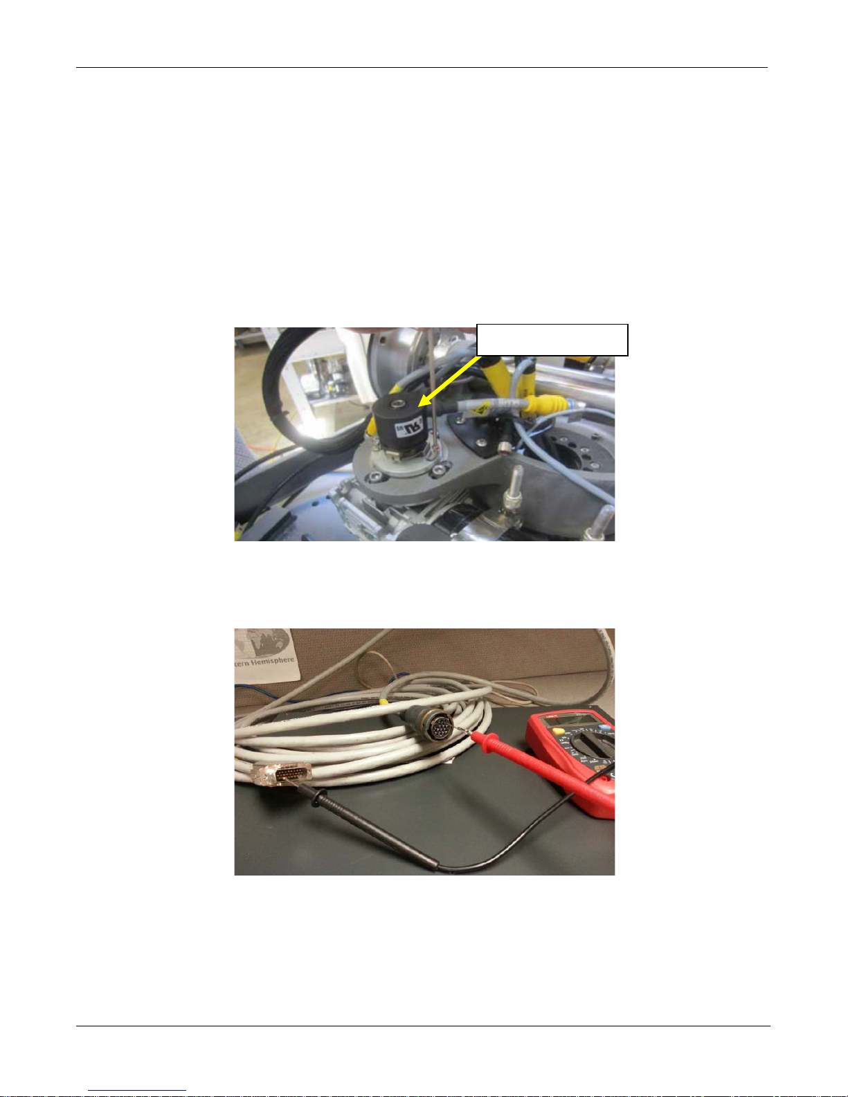
Azimuth Encoder
2. If the Mobile Platform physically moves but the angle doesn’t change
Possible Causes:
• Azimuth Encoder
• Sensor Cable
• Internal Wiring Harness
• 7000 Controller
a. Please ensure the Sensor Cable is securely connected to the 7000 Controller and Platform.
Reseat the Sensor Cable and the Azimuth Encoder cable. If the issue persists continue to the next
step.
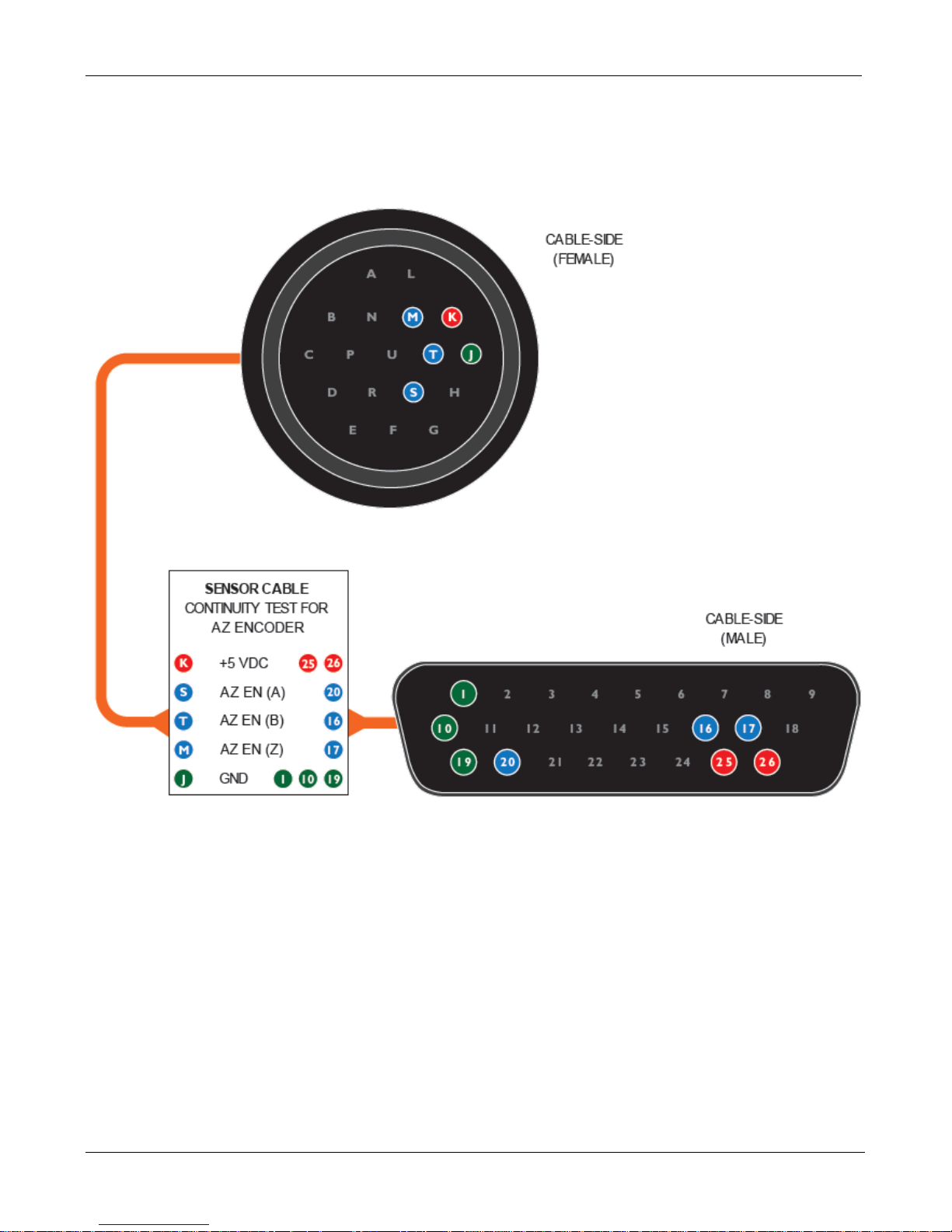
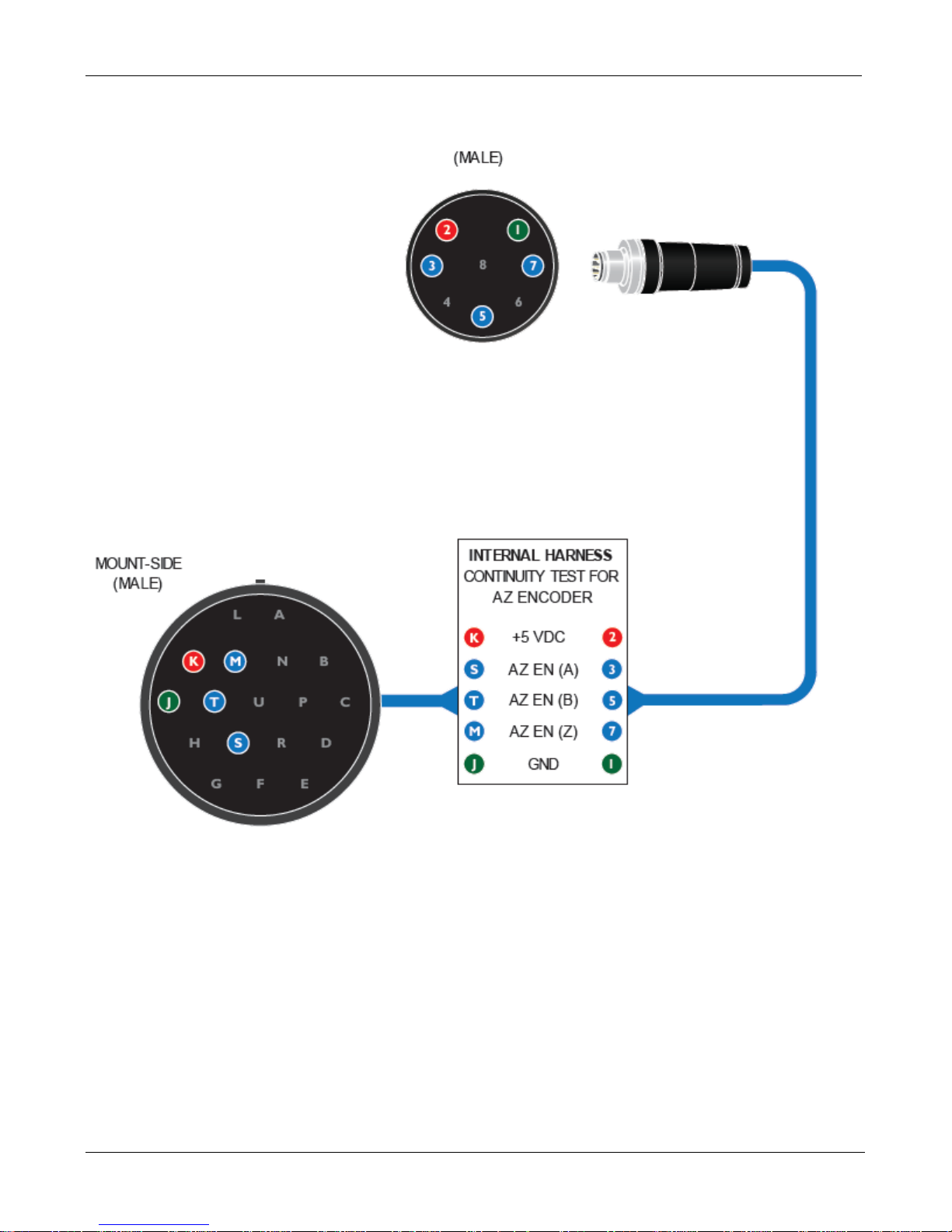
b. Use the Azimuth Encoder Sensor Circuit Diagram on the following page to confirm continuity of the
cabling. Set the voltmeter to beeper or continuity mode.
c. If either the sensor cable or internal harness fails continuity please Contact C-COM Technical
Support for further instructions.
d. If the cabling passes continuity, this will conclude the issue is the Azimuth Encoder. Please
Contact C-COM Technical Support for further instructions.
C-COM Satellite Systems Inc.
Page 29
iNetVu New Gen Troubleshooting Guide
Page 29 of 68
Sensor Cable and Internal Harness Continuity Test for AZ Encoder
Sensor Cable
C-COM Satellite Systems Inc.
Page 30
iNetVu New Gen Troubleshooting Guide
Page 30 of 68
Internal Harness
C-COM Satellite Systems Inc.
Page 31

iNetVu New Gen Troubleshooting Guide
Page 31 of 68
OVER CURRENT PROTECTION
C-COM Satellite Systems Inc.
Page 32
iNetVu New Gen Troubleshooting Guide
Page 32 of 68
C-COM Satellite Systems Inc.
Over Current Protection
Error Code Definition:
0x9003 --- EL Over current
0x9004 --- AZ Over current
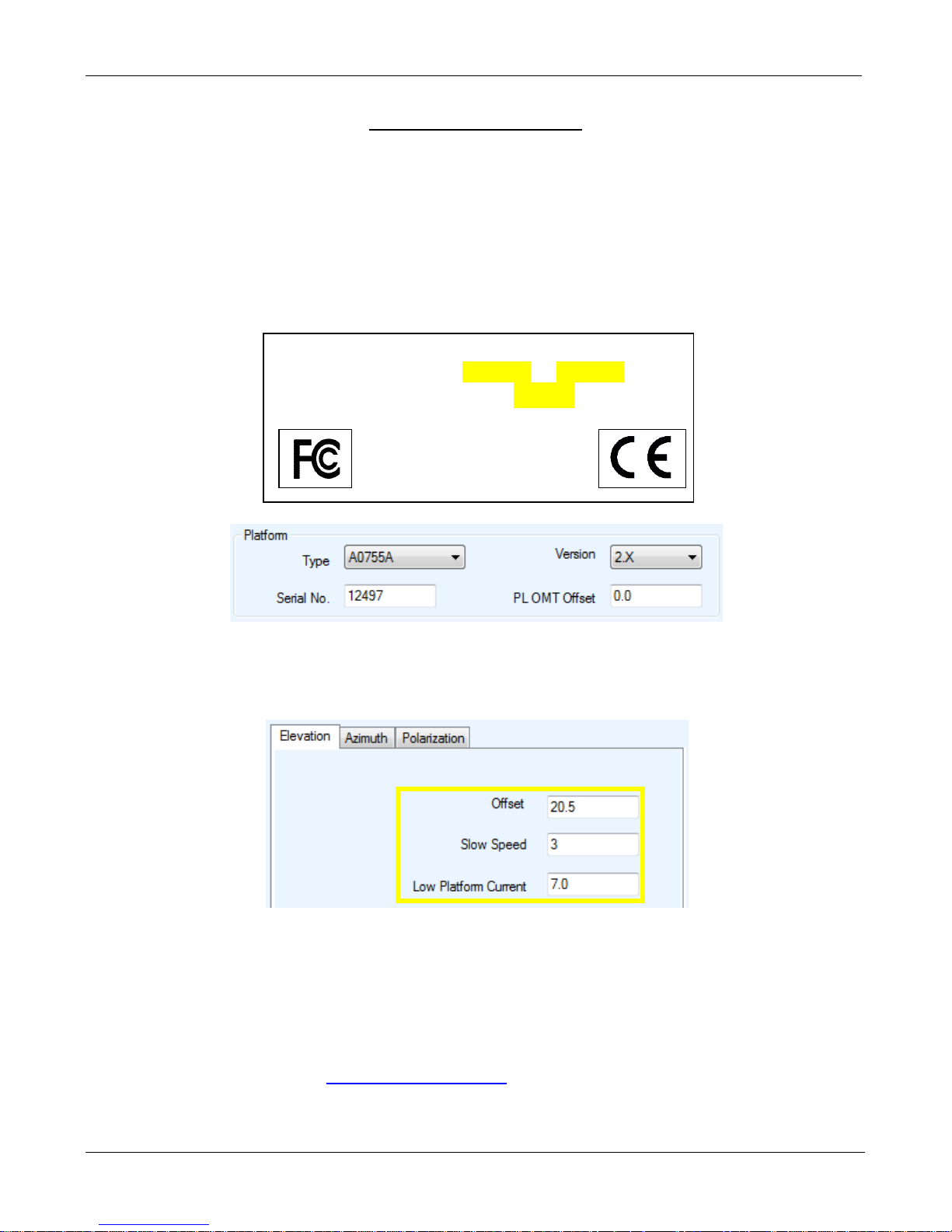
Current used to move the Platform exceeds the fixed limit, which resulted in a current spike.
1. Ensure the correct platform Type is selected with the correct version and serial number.
Model: iNetVu A0755A Ver: 2.1
Serial: 1250A12497
www.c-comsat.com
Made In Canada
Assembled from tested components.
Complete system not tested
2. Check the Speeds and Limits for all angles to verify that they are at default. Please see “Default
Limits and Configuration Data Tables” in the 7000 Series Controller User Manual. Reselecting
the Platform Type will reset these to their default values.
3. If there is any snow/ice buildup or if the unit has been idle in below freezing (-25 to -30 +)
temperatures for extended periods of time. You may have to move the unit indoors to free up the
platform. Attempt to move the antenna manually with “HI SPEED ON” from the front panel
controls. Try to stow and deploying again.
4. Increasing the Low Platform Current for that specific angle in increments of 1.0 to test.
5. Contact C-COM Support at
[email protected] for further assistance.
C-COM Satellite Systems Inc.
Page 33

iNetVu New Gen Troubleshooting Guide
Page 33 of 68
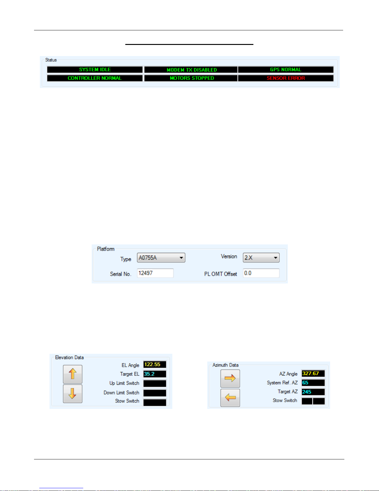
Quick Tip: A red indicator on the iNetVu Controls screen indicates a critical failure.
SENSOR ERRORS
C-COM Satellite Systems Inc.
Page 34
iNetVu New Gen Troubleshooting Guide
Page 34 of 68
ERROR 0x8911 - Sensor Errors
The “Sensor Error” message will only appear if sensor cable becomes loose from the controller end,
and only in the stowed position. If any of the angles are in RED/YELLOW this will still indicate a
sensor related failure and should be treated as such.
Possible failed components include:
• Sensor Cable (Although the Legacy and New Gen Sensor Cables appear the same they are
NOT interchangeable)
• Azimuth Encoder
• Elevation Tilt Sensor
• Wiring Harness
• 7000 Controller
Solution:
Step 1:
a. From the Maintenance Screen, ensure the correct Platform Type is selected.
b. Ensure that the sensor cable from the Controller and Platform side is properly connected
and not damaged. Clean and reseat all related sensor cable connectors.
c. Using the manual controls move the platform on AZ or EL to see if the angle updates.
d. If the EL/AZ angle is still incorre ct or is flashing Red/Yellow. Proceed to step to the next
step.
Example A: Elevation Sensor Failure Example B: Azimuth Sensor Failure
C-COM Satellite Systems Inc.
Page 35
iNetVu New Gen Troubleshooting Guide
Page 35 of 68
Step 2:
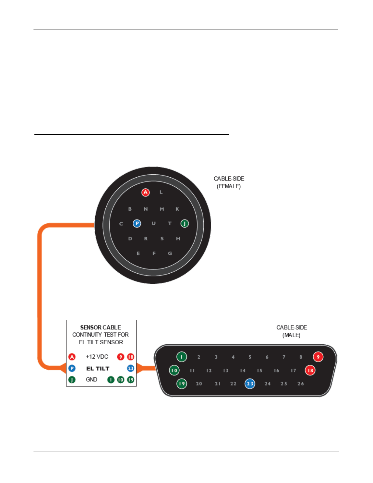
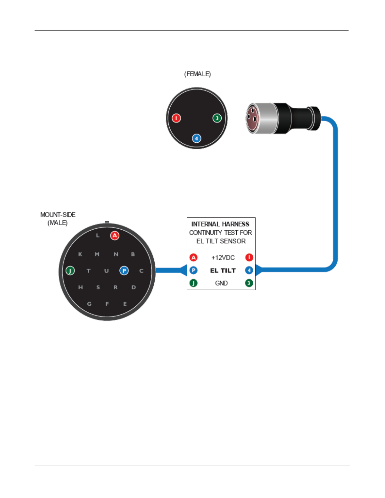
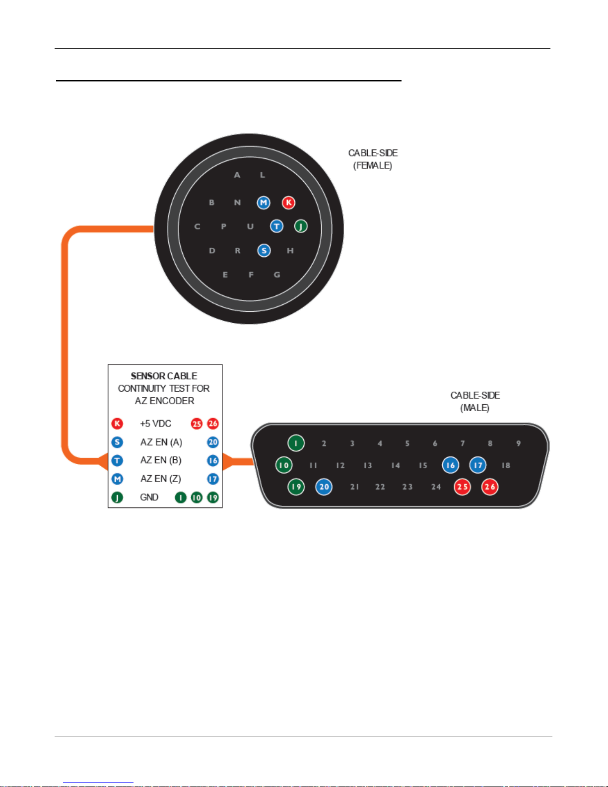
a. Use the Sensor Circuit Diagram to confirm continuity of the Sensor Cabling. If the Sensor
Cabling passes continuity the problem could be related to the Sensor itself.
b. If the Sensor Error is related to either Polarization or Elevation you could swap the PL Tilt
with the EL Tilt (or vise versa) to see if the angle issue is resolved. Please see the New
Generation Service Manual for exact location of these parts.
Sensor Cable and Internal Harness Continuity Test for EL Tilt
Sensor Cable for EL Tilt
C-COM Satellite Systems Inc.
Page 36
iNetVu New Gen Troubleshooting Guide
Page 36 of 68
Internal Harness for EL Tilt
C-COM Satellite Systems Inc.
Page 37
iNetVu New Gen Troubleshooting Guide
Page 37 of 68
Sensor Cable and Internal Harness Continuity Test for AZ Encoder
Sensor Cable
C-COM Satellite Systems Inc.
Page 38
iNetVu New Gen Troubleshooting Guide
Page 38 of 68
Internal Harness
C-COM Satellite Systems Inc.
Page 39

iNetVu New Gen Troubleshooting Guide
Page 39 of 68
COMPASS
Quick Tip: Compass interference? Try overriding the com pass and using full search.
C-COM Satellite Systems Inc.
Page 40
iNetVu New Gen Troubleshooting Guide
Page 40 of 68
This END
This END
Compass value is not accurate
Cause:
A foreign object (e.g. metal, magnet) is radiating a magnetic field that is obscuring the compass from
obtaining a reliable reading.
Solution:
1. Ensure there are no foreign objects (e.g. metal, magnet) around the Mobile Platform.
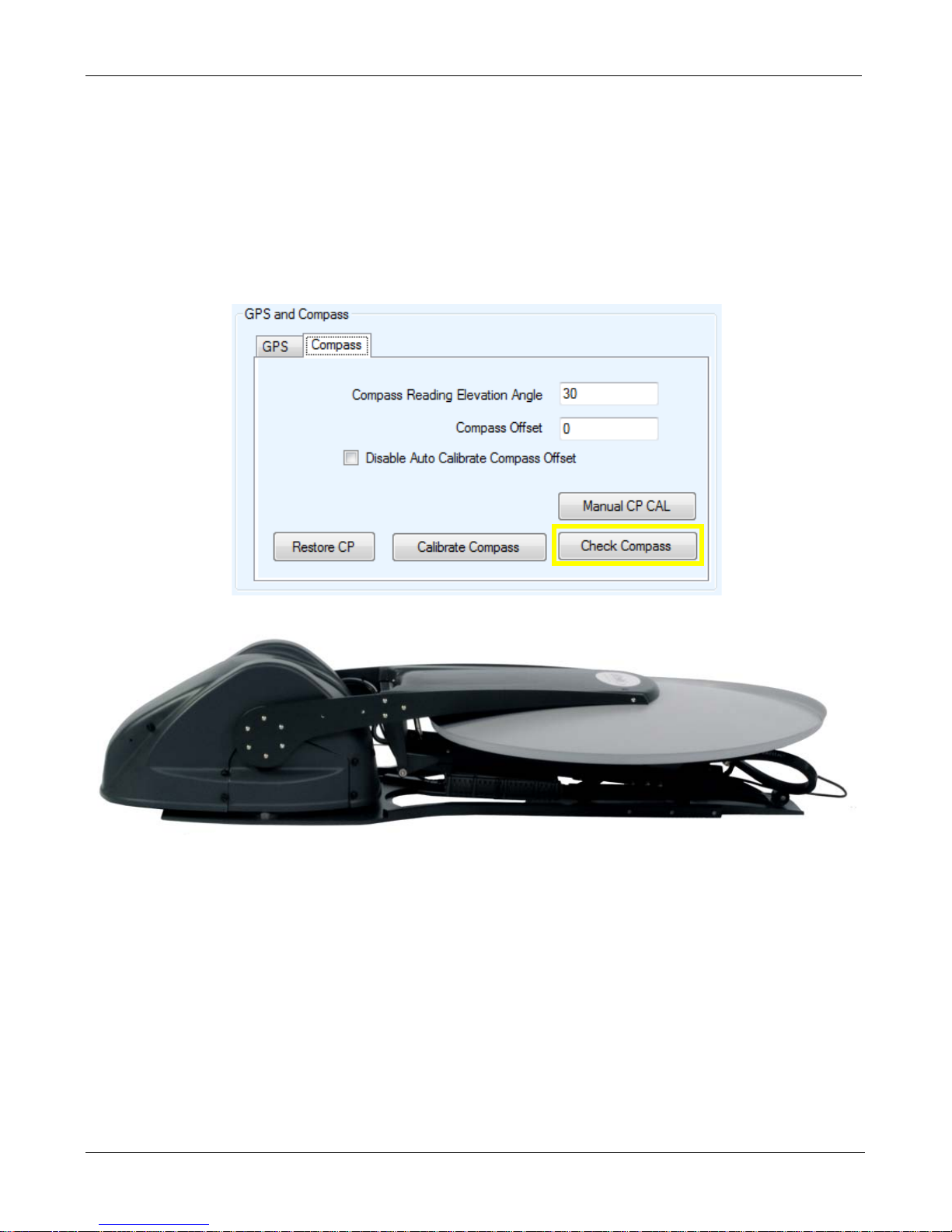
2. Go to Maintenance.
3. Click Check Compass.
Faces North
4. The Mobile Platform will now rotate on 90 ° intervals. 0, 90, 180, 270(-90). These figures are in
5. Pay attention to the Compass Heading on the Controls Screen as well as the Message Panel,
6. If you receive Cal/Test Compass Success, you may continue operating normally.
7. If your compass fails accuracy, compass may require Restoring. Please use following
Faces South
relation to true North
and record the values.
procedure to restore the compass.
C-COM Satellite Systems Inc.
Page 41
iNetVu New Gen Troubleshooting Guide
Page 41 of 68
Warning: The New Generation Platforms (these include and not limited to 755A, 981A, 985A and
1201A) are equipped with newer versions of the compasses which are factory calibrated and Do NOT
Require Calibration. Do not calibrate unless instructed by C-COM Technical Support.
Restoring the Compass
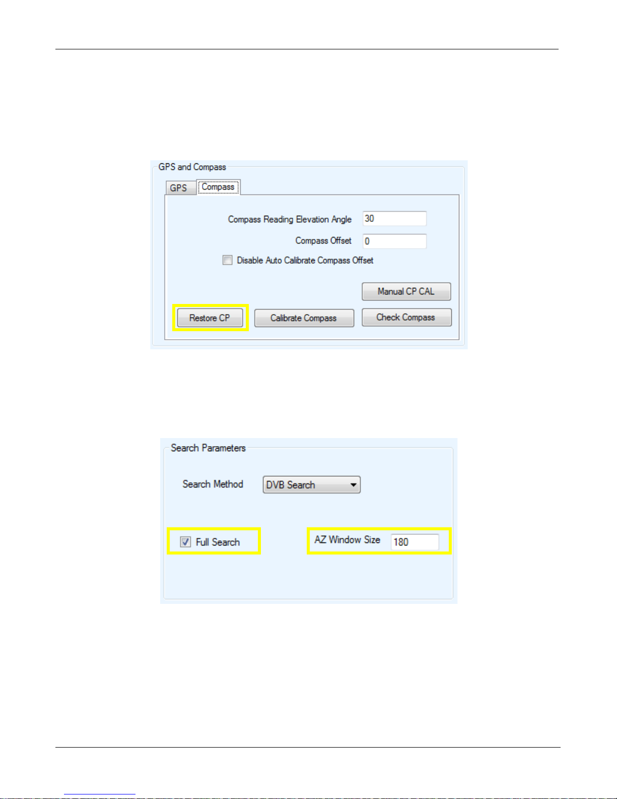
1. Launch the iNetVu Software and proceed to the Maintenance/Compass Tab. Click Restore CP
2. Check the Compass once more, if all works well, you may continue.
3. If the compass still fails there may be some type of interferences or require replacement. You
can try overriding the compass and use Full Search in this case. From Configur ation / Search
Parameters select Full Search and click Save All.
C-COM Satellite Systems Inc.
Page 42

iNetVu New Gen Troubleshooting Guide
Page 42 of 68
GPS
Quick Tip: GPS failure? For emergency deployment, try GPS Override and enter the LAT/LONG
manually.
C-COM Satellite Systems Inc.
Page 43
iNetVu New Gen Troubleshooting Guide
Page 43 of 68
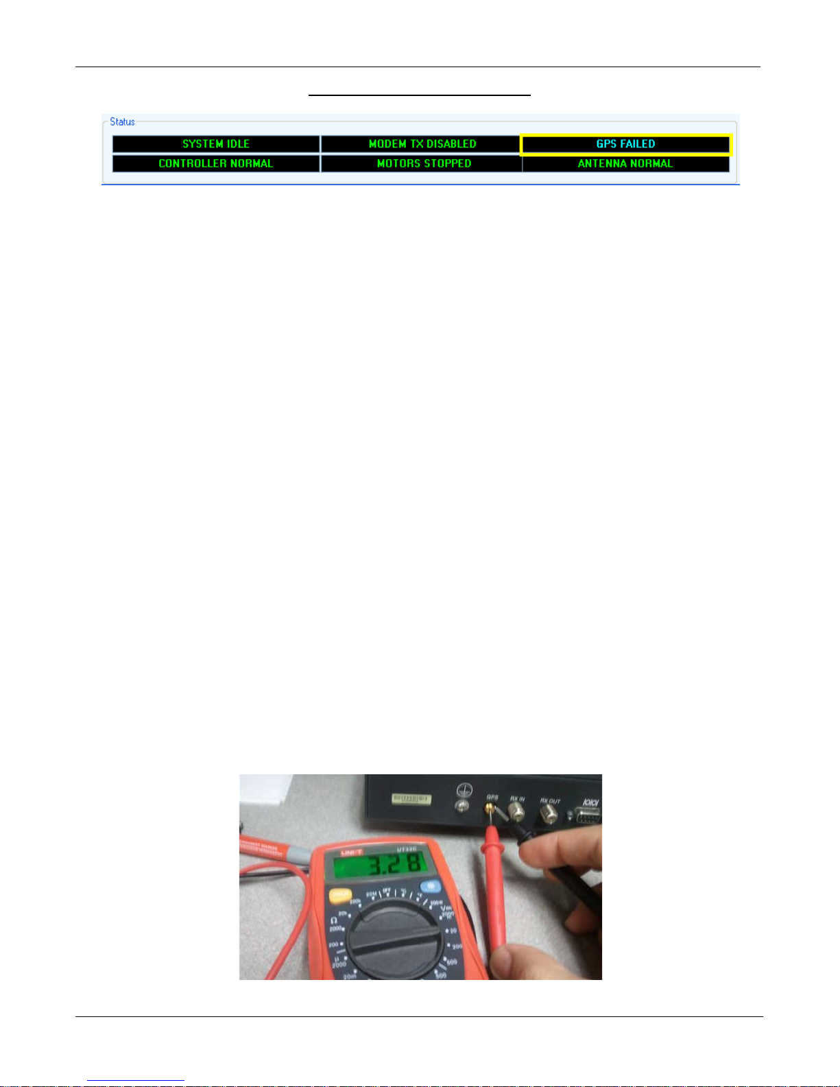
ERROR 0X8914 - GPS Failed
Note: Some Glonass Antenna may take longer than normal to acquire signal. Please contact C-COM
technical support for more information.
Cause 1:
GPS Antenna is not connected.
Solution 1:
Verify GPS Antenna is securely connected to the 7000 Controller.
Cause 2:
A foreign object is obstructing the GPS Antenna.
Solution 2:
Ensure there are no foreign objects obstructing the GPS antenna from a clear view of the sky.
Cause 3:
Overcharge in the GPS Antenna Cable.
Solution 3:
Turn off the Controller Unplug GPS Antenna from the back of the 7000 Controller and ground it. Wait 5
seconds. Re-connect GPS Antenna and turn on the Controller. Observe the GPS Coordinates on the
Controls menu. It may take a couple of minutes to update.
Cause 4:
The Controllers GPS port or the GPS has failed.
Solution 4:
Test the Controllers GPS port for 3.3 Volts. If you are not getting any Voltage then the controller is the
issue. If you are getting Voltage the GPS Antenna may have failed. If you have a spare GPS antenna
please test. Please contact C-COM Technical Support for further assistance.
Insert a wire or paperclip for better contact
C-COM Satellite Systems Inc.
Page 44
iNetVu New Gen Troubleshooting Guide
Page 44 of 68
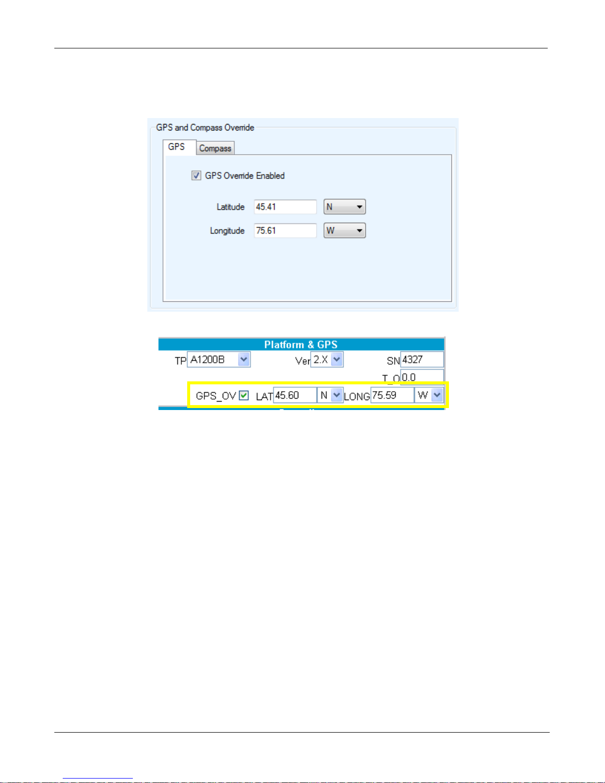
For emergency deployment the GPS can be overridden and the LAT/LONG entered manually
from the iNetVu 7000 Software or Web Interface.
iNetVu 7000 Software
7000 Controller Web Interface
C-COM Satellite Systems Inc.
Page 45

iNetVu New Gen Troubleshooting Guide
Page 45 of 68
STOW
Quick Tip: The controller cannot stow the platform if any of the stow limit switches fail to enable.
C-COM Satellite Systems Inc.
Page 46
iNetVu New Gen Troubleshooting Guide
Page 46 of 68
ERROR 0xA003 / 0xA006 - Stow Failed
Status Definitions:
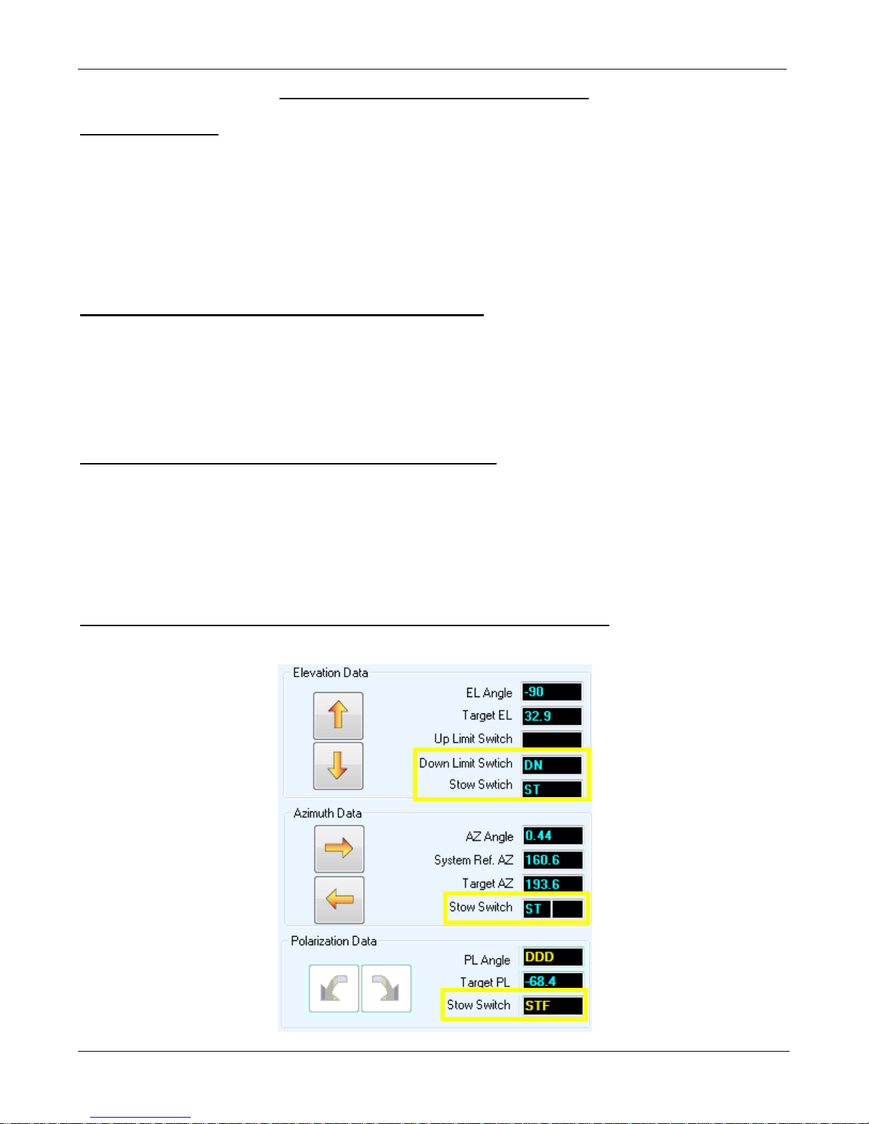
• AZ ST not enabling when the unit is “Stowed”.
For all Ka New Generation Platforms the PL ST should appear as STF. The mobile platform
will center on AZ enabling the AZ ST confirming the platform is in the “home” position. At which
point the antenna begins t o lower on elevation until fully stowed. During this routine if the AZ
ST Switch fails to enable it will not allow the stow command to complete resulting in ERROR:
0xA003 or 0xA006.
These switches not getting enabled can be caused by:
• The Controller
• The Sensor Cable
• The Internal Wiring Harness
• The Switch Itself (AZ)
• The Switch is too close to the target therefore needs to be adjusted
How to determine what component is causing the issue.
a. We will need to move the antenna to the home position manually. Using the front panel of the
controller manually center AZ=0.0 (visually verify)
b. From the iNetVu Mobile 7000 Controls screen, note which ST is not ON. If the PL STF is not
ON this mean the platform is improperly configured on the controller. If the AZ ST is not ON
please proceed to Step 1. If both are ON attempt to auto stow the antenna again.
The screen shot below is a normal scenario when successfully stowed:
755/985 stow position
C-COM Satellite Systems Inc.
Page 47
iNetVu New Gen Troubleshooting Guide
Page 47 of 68
Step 1: Testing the Limit Switch.
Testing Azimuth Home and Away Limit Switches
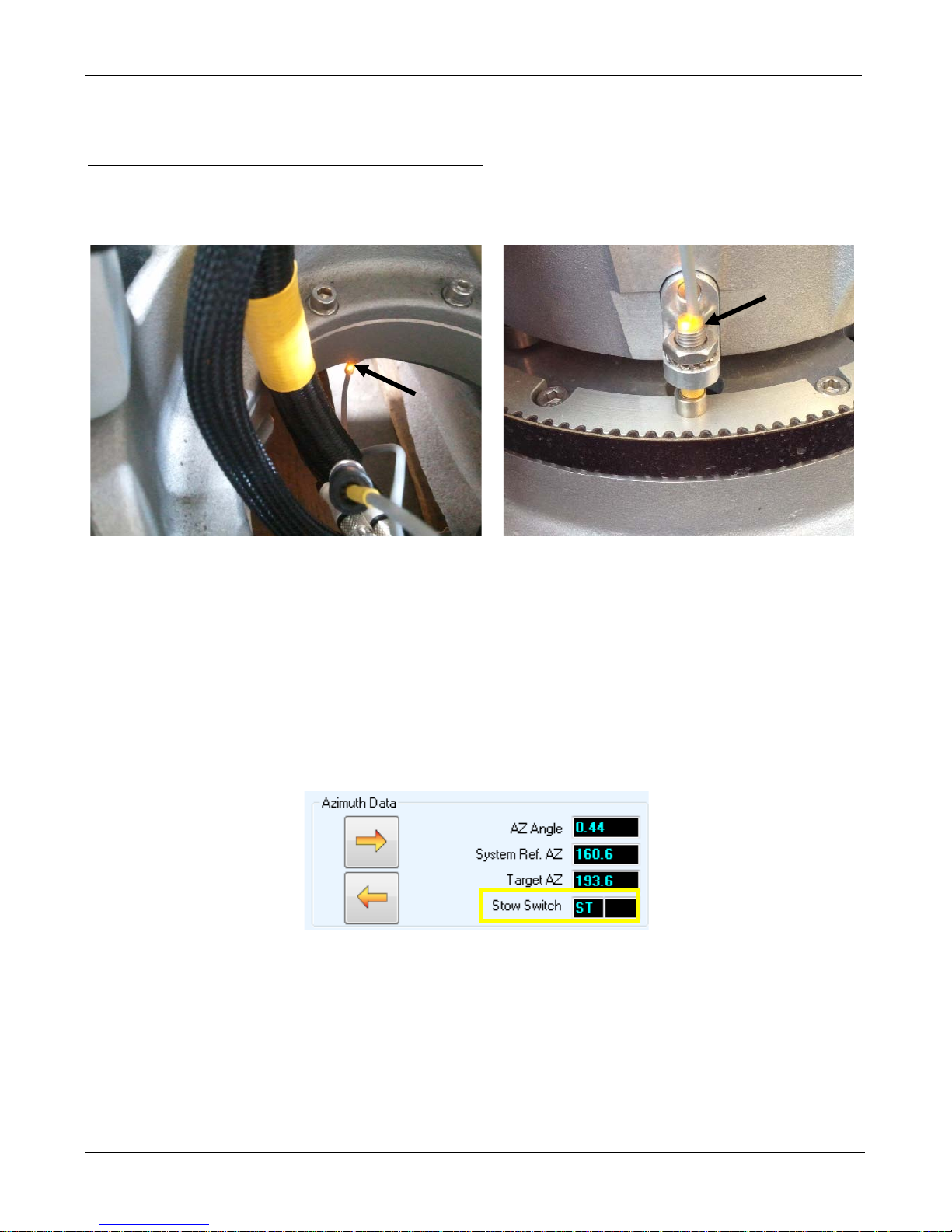
Certain Antenna Versions have the AZ Home and Away Switches installed on the underside or outside
of the Azimuth assembly.
a. Verify that the limit switch is connected to the wiring harness. The switch must be aligned with
the target to activate. If necessary remove the switch from its housing.
• Antennas with the switch on the underside of the AZ base will activate when not in contact
with metal indicated by an LED on the switch and the AZ ST from the 7000 Software
Controls screen. When the switch is moved away from any metal object it should activate.
• Antennas with the switch on the outside of the AZ base will activate when in contact with
the metal indicated by an LED on the switch and the AZ ST from the 7000 Software
Controls screen. When any metal object comes in contact with the switch is should
activate.
b. From the iNetVu Mobile 7000 Controls screen does the AZ ST turn ON?
If YES, it concludes the limit switch is not aligned or is too close/ far to the target and it needs to be
adjusted. Loosen the nut and slowly thread the Sensor away/closer until AZ ST comes ON. Tighten
the nut.
If NO, proceed to Step 2
C-COM Satellite Systems Inc.
Page 48
iNetVu New Gen Troubleshooting Guide
Page 48 of 68
A&C
AZ ST
Step 2: Testing the Wiring Harness.
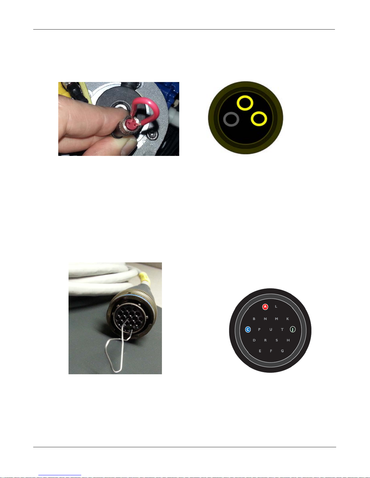
a. Disconnect the switch from the internal wiring harness and place a paper clip or a looped wire
in the connector going to the wiring harness.
b. From the iNetVu Mobile 7000 Controls screen does the AZ ST come ON?
If YES, this concludes the Switch has failed
If NO, proceed to Step 3
Step 3: Testing the Sensor Cable.
a. Disconnect the sensor cable from the Platform and place the paper clip on the sensor cable
shorting out the pins corresponding to the Switch you wish to test.
b. From the iNetVu Mobile 7000 Controls screen does the AZ ST come ON?
If YES, this concludes the Wiring Harness has failed
for
If NO, proceed to Step 4
C-COM Satellite Systems Inc.
Page 49

iNetVu New Gen Troubleshooting Guide
Page 49 of 68
Step 4: Testing the 7000 Controller.
a. Disconnect the sensor cable from the 7000 Controller and place the paper clip on the
connector shorting out the pins corresponding to the Switch you wish to test.
6&9 and 6&18 for Azimuth ST
b. From the iNetVu Mobile 7000 Controls screen does the AZ ST come ON?
If YES, this concludes the Sensor Cable has failed
If NO, this concludes the 7000 Controller has failed
Please contact C-COM Technical Support for further assistance at
C-COM Satellite Systems Inc.
Page 50
iNetVu New Gen Troubleshooting Guide
Page 50 of 68
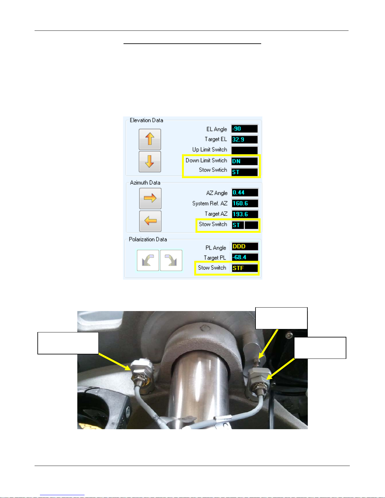
Elevation Stow
Elevation UP
Elevation Hard
ERROR 0X8010 - Can't Stow (EL Limit)
Cause: This error will occur if the Elevation Stow switch fails to come on during the last stow attempt.
The controller will no longer allow the user to stow the antenna automatically until the switch is fixed.
Solution:
a. Using the manual controls on the front of controller, move the platform to the stow position
on 2 axes. Move the AZ=0.0, then begin to lower the antenna until stowed.
755/985 stow position
b. Once the controller confirms The EL ST switch is activated, a message indicating “EL Limit
Fixed” will appear and the user can proceed stowing the platform automatically.
Stop Target
Limit Switch
Switch
If the Elevation ST does not come on in the Stowed position then the switch will need to be tested.
Proceed to Step 1
C-COM Satellite Systems Inc.
Page 51
iNetVu New Gen Troubleshooting Guide
Page 51 of 68
Step 1: Testing the Limit Switch.
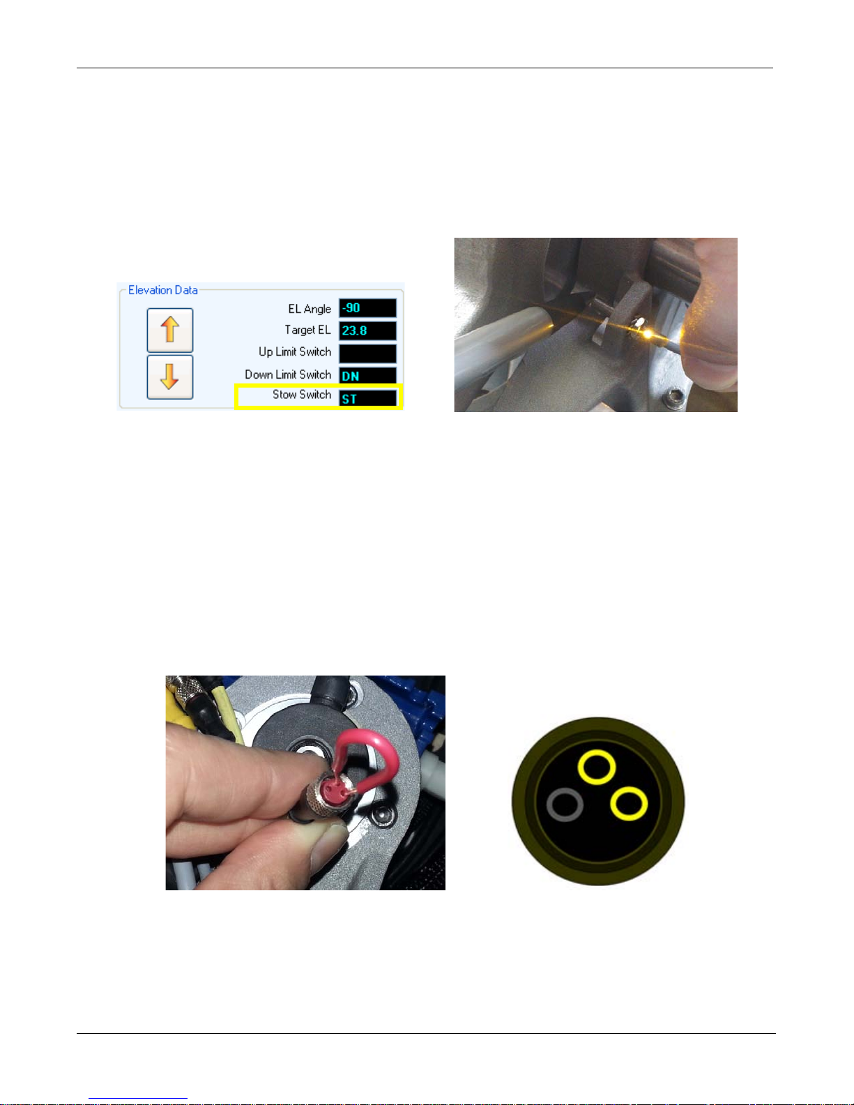
a. Verify that the limit switch is connected to the wiring harness.
b. Place a metal object to the tip of the limit switch so see if the switch activates. This will be
indicated by an LED on the switch or from the Controls screen of the iNetVu Mobile 7000
software.
c. From the iNetVu Mobile 7000 Controls screen does the Elevation ST come ON?
If YES, it concludes the limit switch is too far from the target and it needs to be brought closer until the
Elevation ST comes on. Loosen the nut and slowly thread the Sensor towards the target until EL ST
comes ON. Tighten the nut.
If NO, proceed to Step 2
Step 2: Testing the Wiring Harness.
a. Disconnect the Elevation limit switch from the internal wiring harness and place a paper clip or
a looped wire in the connector going to the wiring harness.
b. From the iNetVu Mobile 7000 Controls screen does the Elevation ST come ON?
If YES, this concludes the Switch has failed
If NO, proceed to Step 3
C-COM Satellite Systems Inc.
Page 52
iNetVu New Gen Troubleshooting Guide
Page 52 of 68
Step 3: Testing the Sensor Cable.
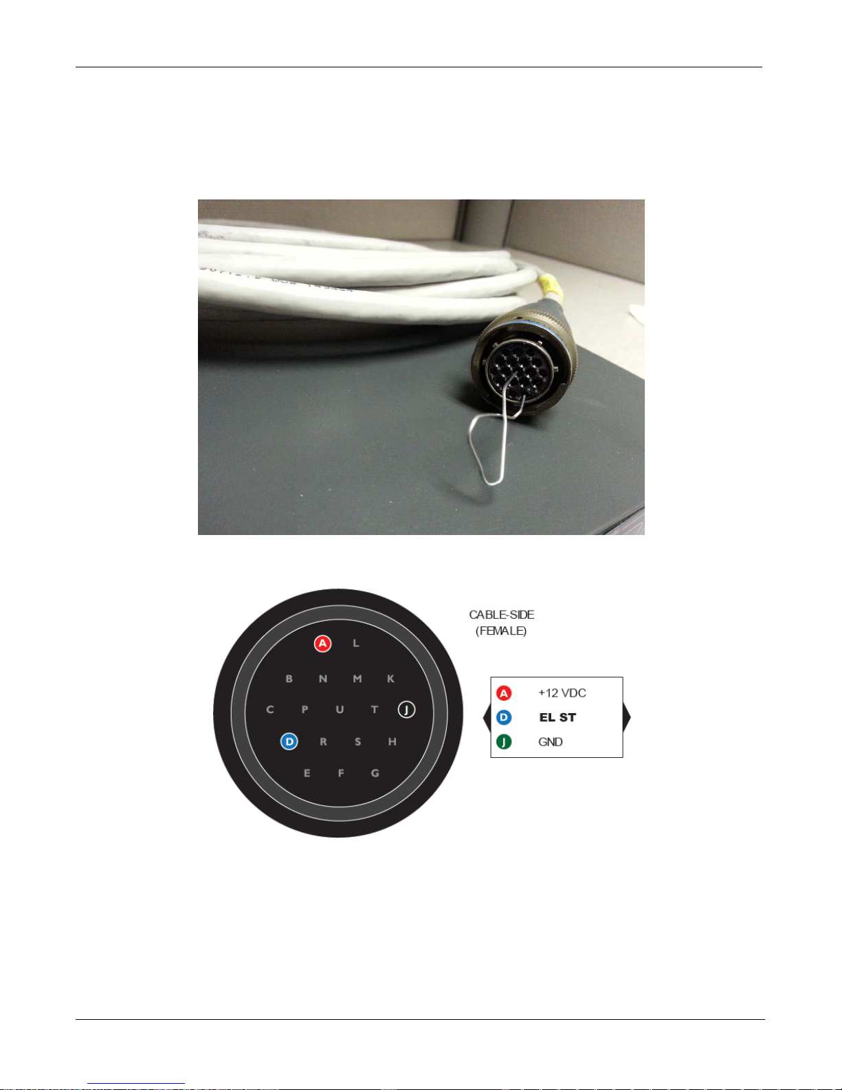
a. Disconnect the sensor cable from the Platform and place the paper clip on the sensor cable
shorting out pins corresponding to the Switch you wish to test.
A&D for EL ST
b. From the iNetVu Mobile 7000 Controls screen does the Elevation ST come ON?
If YES, this concludes the Wiring Harness has failed
If NO, proceed to Step 4
C-COM Satellite Systems Inc.
Page 53
iNetVu New Gen Troubleshooting Guide
Page 53 of 68
Step 4: Testing the 7000 Controller.
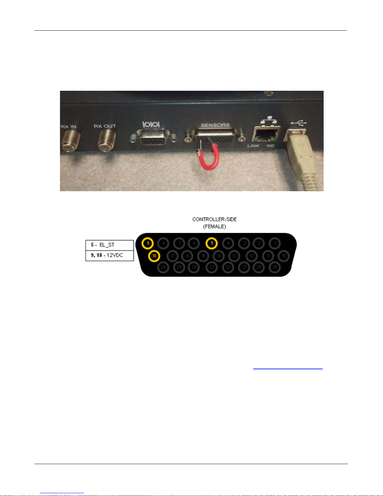
a. Disconnect the sensor cable from the 7000 Controller and place the paper clip on the
connector shorting out pins corresponding to the Switch you wish to test.
5&9 and 5&18 for Elevation ST
b. From the iNetVu Mobile 7000 Controls screen does the Elevation ST come ON?
If YES, this concludes the Sensor Cable has failed
If NO, this concludes the 7000 Controller has failed
Please contact C-COM Technical Support for further assistance at
C-COM Satellite Systems Inc.
Page 54

iNetVu New Gen Troubleshooting Guide
Page 54 of 68
RF SIGNAL LOSS
C-COM Satellite Systems Inc.
Page 55

iNetVu New Gen Troubleshooting Guide
Page 55 of 68
ERROR 0X8915 - RF IS TOO LOW or TRIA IS NOT BEEPING
NOTE: This issue differs from a Ku setup. The TRIA has two methods of connection, a Single IFL (TX
only) or Dual IFL (RX and TX). The TRIA MUST be beeping (Tooway & SurfBeam 2 only) when
searching for satellite. The following steps will help isolate the cause of the issue.
Step 1:
• Verify all the physical connections are properly connected by referring to Quick Start Guides.
• Verify the controller is properly configured by referring to the Quick Start Guides.
• The modem must be provisioned. Please contact your NOC.
• If the RX connection was corrected, please continue as normal.
• For Tooway and SurfBeam 2 setup, if the TRIA is still not beeping while in installer/search
modes continue troubleshooting your setup.
• If RF is still in RED/YELLOW continue troubleshooting your setup.
RF Signal Not Being Detected (Single IFL Cable Setup)
RF Signal Not Being Detected (Dual IFL Cable Setup)
C-COM Satellite Systems Inc.
Page 56
iNetVu New Gen Troubleshooting Guide
Page 56 of 68
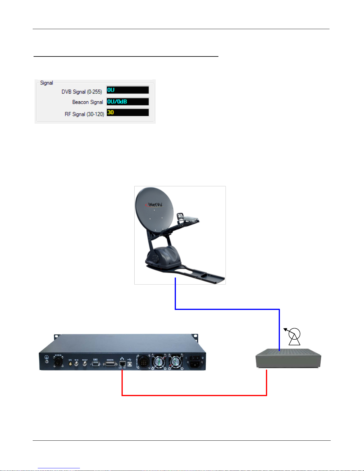
TX
Ethernet
Only TX Cable
RF Signal Not Being Detected (Single IFL Cable Setup)
RF Signal in Yellow/Red: (Abnormal State)
This indicates the controller is not configured correctly, and you will not be able to deploy the dish
resulting in ERROR 0X8915 - RF IS TOO LOW. Ensure the controller is configured correctly (Tooway
or SurfBeam 2 Auto Acquire) using the Quick Start Guides. Otherwise proceed to Ste p 2.
Diagram for Single IFL Cable (TX Only)
goes to TRIA
C-COM Satellite Systems Inc.
Page 57
iNetVu New Gen Troubleshooting Guide
Page 57 of 68
Step 2:
• Our next step is to test voltage on the hardware to determine if our power source is making it
all the way up to the LNB.
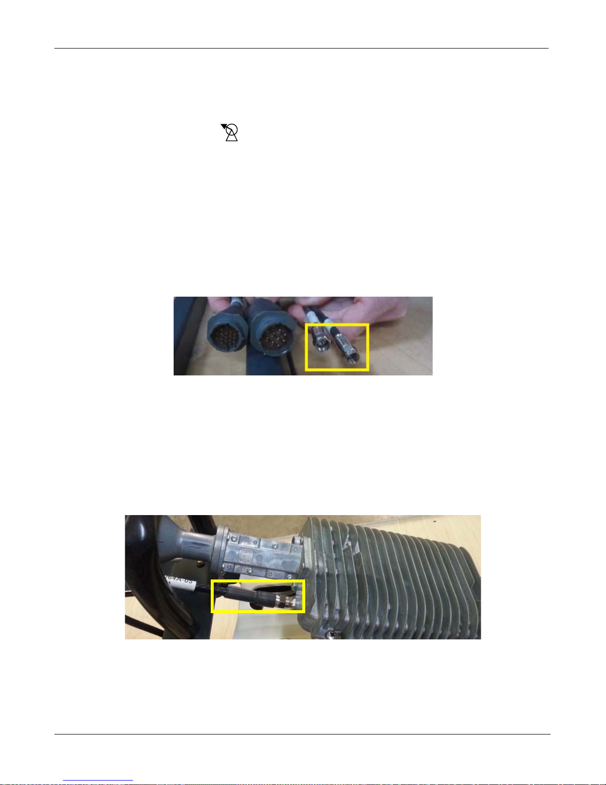
• Starting with the Modems port, disconnect the coax cable and using a volt meter to
determine if the modem is outputting voltage. Please check with your ISP or satellite modem
provider to determine what the normal output should be.
• If no voltage is displayed, please exchange the modem or contact your service provider.
• If proper voltage is displayed, reconnect the cable and proceed to Step 3.
Step 3:
• Disconnect the coax cable going into the “TX” cable on the antenna.
• Measure voltage on this cable. If the voltage does not match the output of the Modem, replace
the cable.
• If the voltage does match, reconnect the cable and proceed to Step 4.
Step 4:
• Disconnect the “TX” coax connected to the TRIA.
• Measure voltage on this cable. If the voltage does not match the Modems output, it concludes
it’s an issue with the internal wire. Please contact C-COM Technical Support for assistance.
• If t he voltage does match, it concludes the TRIA is the issue. Please replace the TRIA and try
again.
C-COM Satellite Systems Inc.
Page 58
iNetVu New Gen Troubleshooting Guide
Page 58 of 68
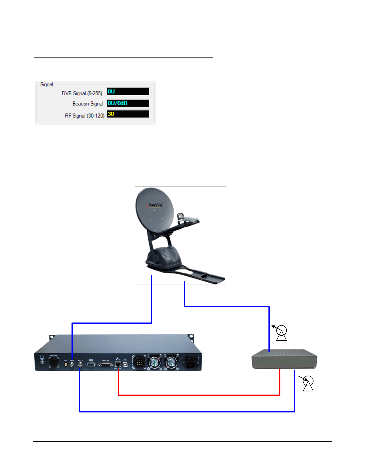
TX
Ethernet
RX OUT
RF Signal Not Being Detected (Dual IFL Cable Setup)
RF Signal in Yellow/Red: (Abnormal State)
As the TRIA is being power by the controller the platform will not be able to deploy and you will receive
ERROR 0X8915 - RF IS TOO LOW. Ensure the controller is configured correctly (Tooway or
SurfBeam 2 Pro) using the Quick Start Guides. Otherwise proceed to Step 2.
Diagram for Dual IFL Cables (RX and TX)
RX IN
C-COM Satellite Systems Inc.
Page 59
iNetVu New Gen Troubleshooting Guide
Page 59 of 68
Step 2:
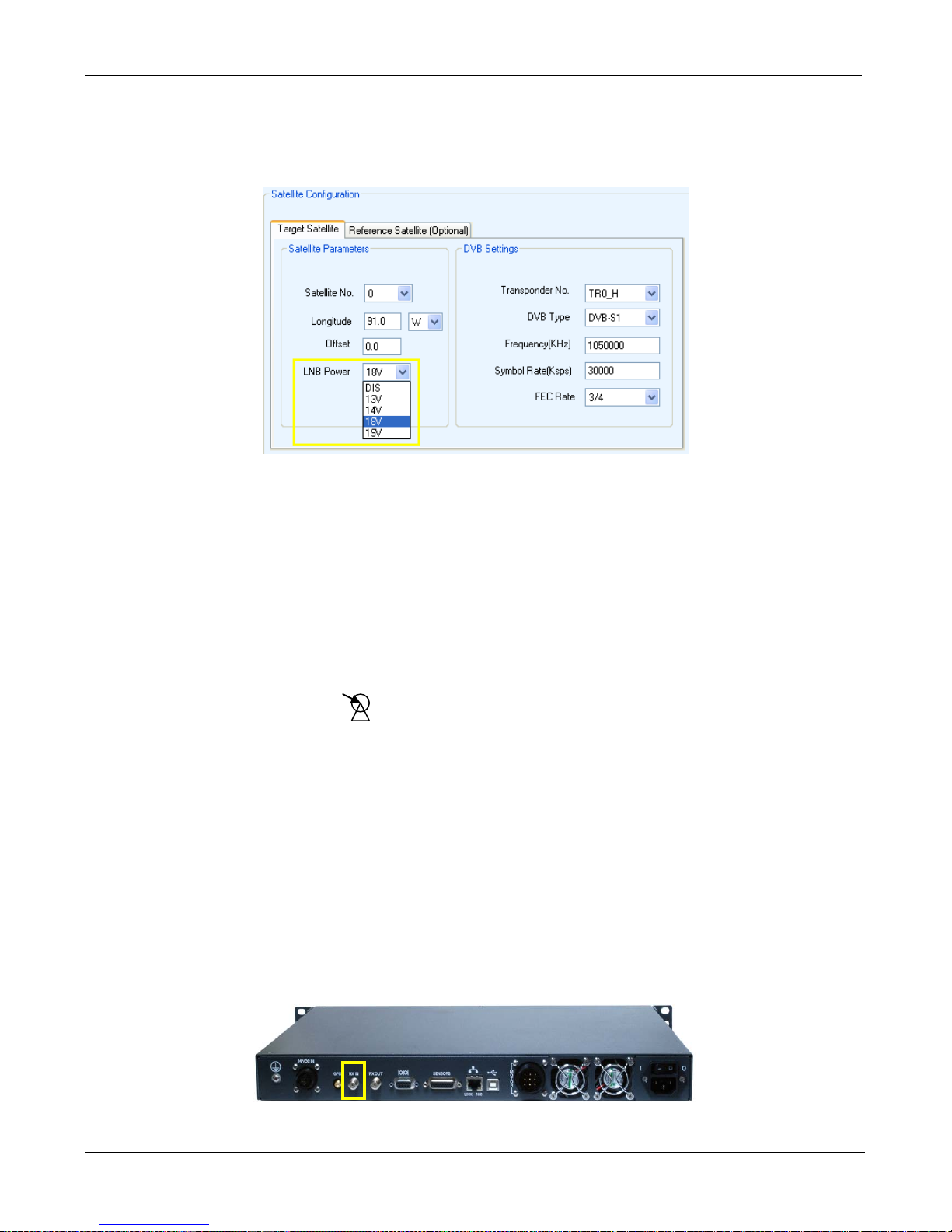
• Verify that the correct “LNB Power” voltage is selected in the iNetVu “Configuration” screen.
• If the incorrect voltage was selected or the option was disabled, please make the necessary
changes and click “Save All” for the changes to t ake effect.
• If the RF signal is still flashing in RED and YELLOW, please proceed to Step 3.
Step 3:
• Our next step is to test voltage on the hardware to determine if our power source is making it
all the way up to the LNB.
• Starting with the Modems port, disconnect the coax cable and using a volt meter to
determine if the modem is outputting voltage. Please check with your ISP or satellite modem
provider to determine what the normal output should be.
• If no voltage is displayed, please exchange the modem.
• If proper voltage is displayed, reconnect the cable and proceed to Step 4.
Step 4:
• Disconnect the coax cable from the Controllers “SAT IN” port and measure voltage on this
port. If the voltage does not match the configured output from the controller, please contact CCOM Technical Support.
• If the voltage does match, reconnect the cable and proceed to Step 5.
C-COM Satellite Systems Inc.
Page 60
iNetVu New Gen Troubleshooting Guide
Page 60 of 68
Step 5:
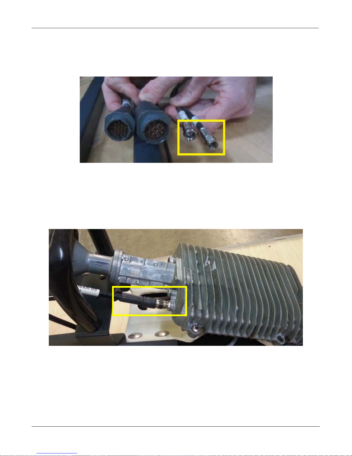
• Disconnect the coax cable going into the “RX” cable on the antenna.
• Measure voltage on this cable. If the voltage does not match the output of the controller,
replace the cable. If the voltage does match, reconnect the cable and proceed to Step 6.
Step 6:
• Disconnect the “RX” coax connected to the TRIA.
• Measure voltage on this cable. If the voltage does not match the controllers output, it
concludes it’s an issue with the internal wire.
• If the voltage does match, it concludes the TRIA may be the issue. Please replace the TRIA
and try again.
Please contact C-COM Technical Support for further assistance.
C-COM Satellite Systems Inc.
Page 61

iNetVu New Gen Troubleshooting Guide
Page 61 of 68
MODEM
C-COM Satellite Systems Inc.
Page 62
iNetVu New Gen Troubleshooting Guide
Page 62 of 68
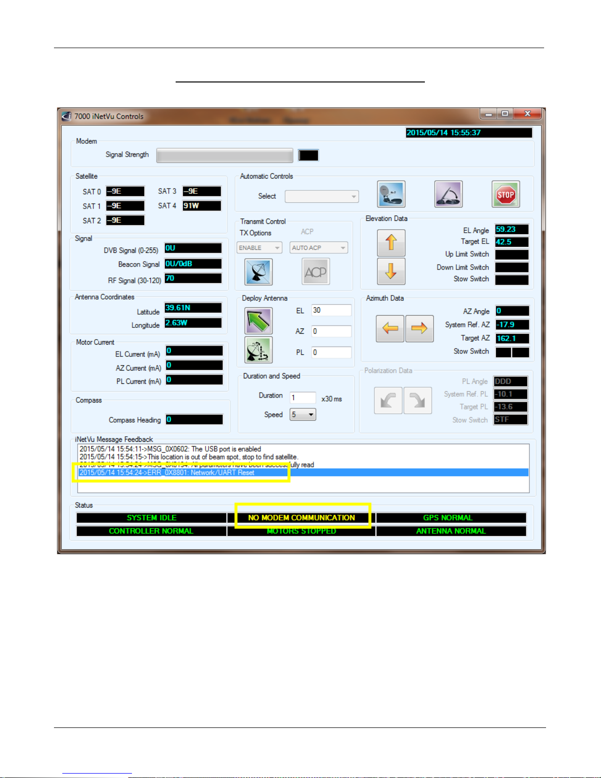
ERROR 0X8801 - No Modem Communication
Modem Status Definitions:
• No Modem Communication: (Error Code---0x8800---0x88FF Network/UART Reset)
Communication between controller and modem has not been established
• Modem TX Disabled:
Communication between controller and modem is active with Transmitter Disabled
• Modem TX Enabled:
Communication between controller and modem is active with Transmitter Enabled
C-COM Satellite Systems Inc.
Page 63
iNetVu New Gen Troubleshooting Guide
Page 63 of 68
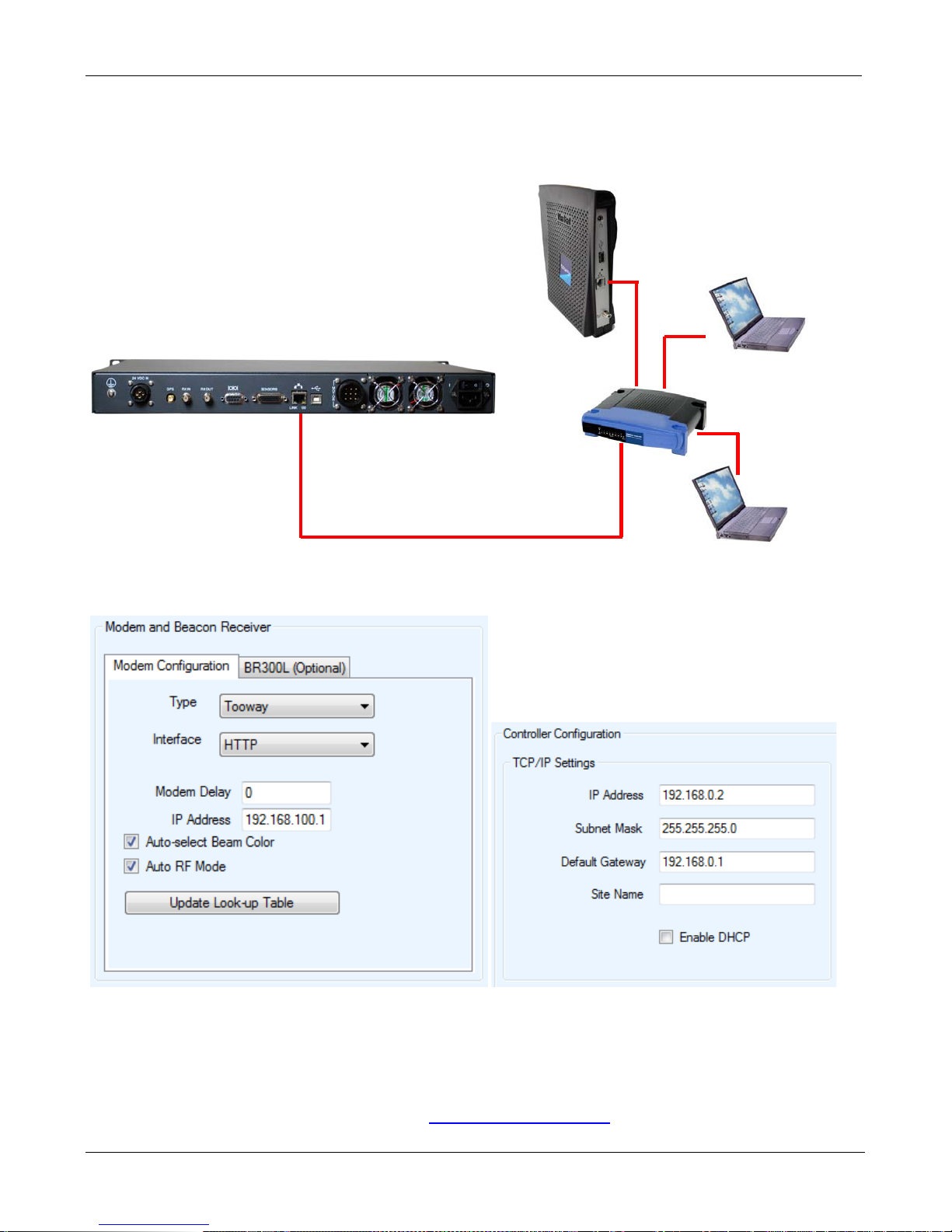
Tooway
Router / Switch
Straight/ X-Over
Example:
Modem IP: 192.168.100.1
a. Ensure the Controller and Modem is connected correctly. Please refer to the iNetVu 7000
Quick Start Guides for more details.
Gateway IP: 192.168.1.1
Controller IP: 192.168.1.2
b. Verify the controller and modems IP address are correct.
Network Cable
c. Connect the Modem directly to the Controllers Ethernet port bypassing any routers, hubs or
switches.
d. Swap out the Ethernet Cable.
Please contact C-COM Technical Support at
C-COM Satellite Systems Inc.
Page 64

iNetVu New Gen Troubleshooting Guide
Page 64 of 68
CANNOT FIND SATELLITE
Quick Tip: In most cases when you cannot find satellite it is due to improper configuration.
C-COM Satellite Systems Inc.
Page 65
iNetVu New Gen Troubleshooting Guide
Page 65 of 68
The following document is a general guide that will assist you if you are unable to find satellite.
Possible Causes:
• Improper Configuration
• Line of Sight (coverage)
• Faulty Hardware
• Modem has not been provisioned
Step 1:
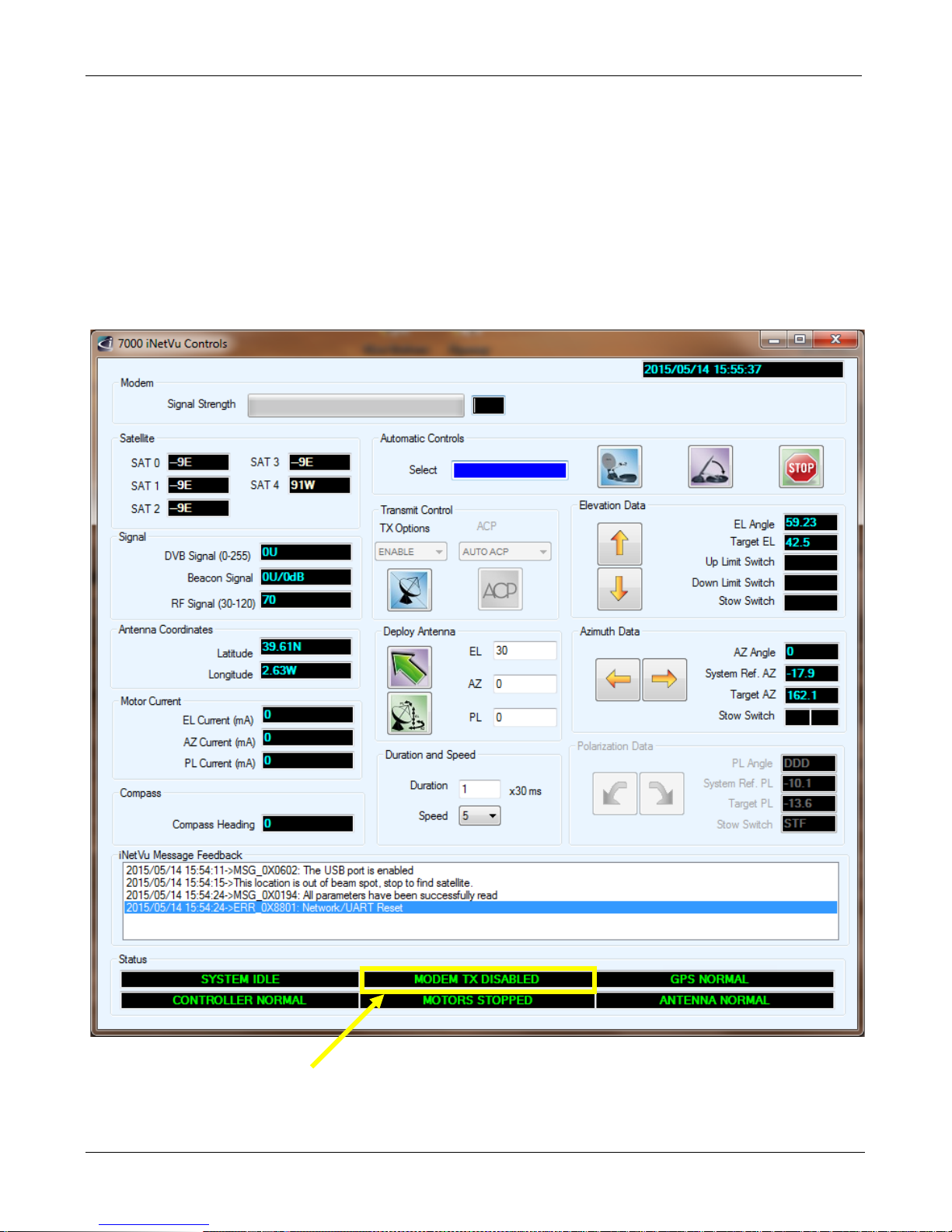
• There must be no RED/YELLOW indicators on the Controls Screen of the iNetVu 7000 software.
• The Modem and Controller must be communicating as shown above. If they are not please refer to
“No Modem Communication” in this Guide.
C-COM Satellite Systems Inc.
Page 66
iNetVu New Gen Troubleshooting Guide
Page 66 of 68
Step 2:
a. The TRIA m ust be beeping while searching for satellite. If it is not, please see the RF SIGNAL
LOSS section of this guide (Tooway & SurfBeam 2 only).
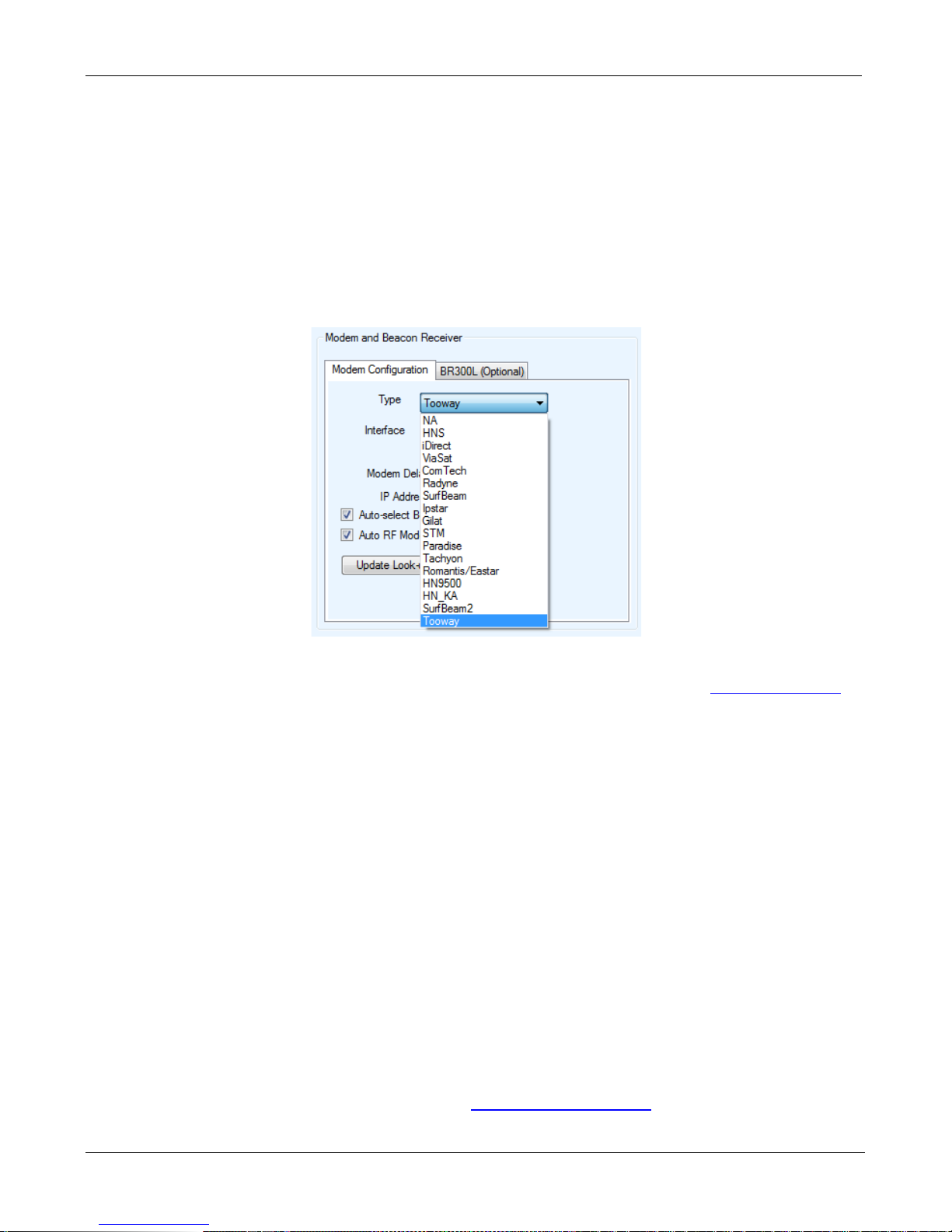
b. The correct Modem Type must be used. There are three (3) Ka Modem Selections.
• Tooway
• SurfBeam 2
• HN Ka
c. Please refer the Quick Start Guide for your specific service type and for proper configuration.
These Quick Start Guides can be found on the software USB drive or from
ftp.c-comsat.com
d. For DVB or RF Search Method, the Satellite Configuration must be exact as provided by your
NOC or service provider.
• For Tooway Service this is preconfigured so no changes are necessary. Please
see the Quick Start Guide for proper configuration.
• For HN Ka Service please see the Quick Start Guide for proper configuration.
• For SurfBeam 2 Auto Acquire Service please see the Quick Start Guide for proper
configuration.
e. If your configuration is correct then you may have a line of sight or coverage issue.
f. If you wish to use Full Search (Recommended for DVB search only). The “Override
Compass” and “Full Search” options must be checked with the “AZ Window” size at 180. For
Tooway Service this must be completed for all BEAMS manually. Please refer to the Quick
Start Guide for instructions.
C-COM Technical Support can be contact at
C-COM Satellite Systems Inc.
Page 67
iNetVu New Gen Troubleshooting Guide
Page 67 of 68
How the iNetVu Search Method Works
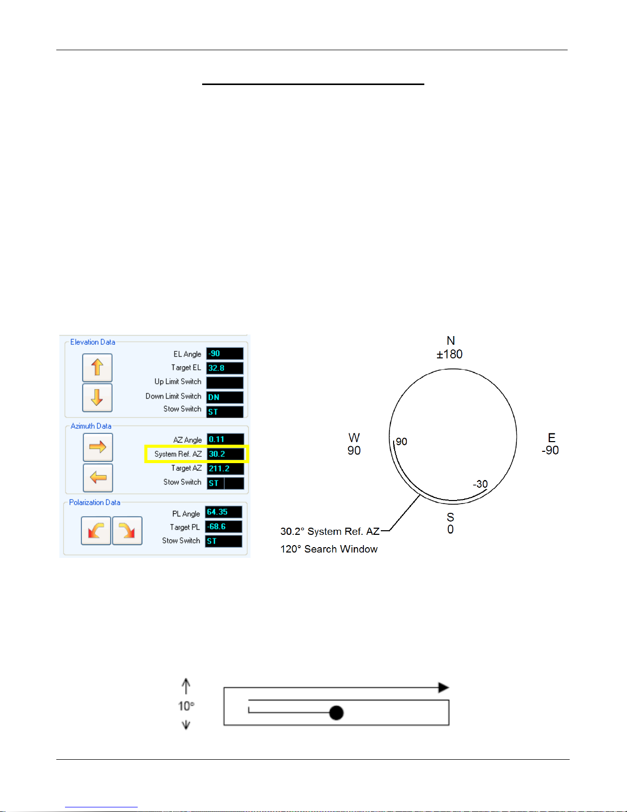
1. The targets for the satellite you are searching on are calculated using the GPS.
For example: 99W GALAXY 16 (G-16)
Latitude: 45.42°
Longitude: -75.69°
Target Elevation = 32.8°
Target Azimuth (true) = 211.1° (This is NOT the azimuth angle of our antenna. The
Target AZ is for informational purposes only.)
2. The antenna will read the compass, and calculate an azimuth search starting point. This is also
known as the “System Ref. AZ”. The antenna will use this value to start searching based on a
120° azimuth search window.
A System Ref. AZ of 30.2° will have a search window of +60° and -60° of this starting
point.
3. If the compass reading is off this may place the search window outside the satellite location.
The compass can be affected my some type of interference so using a full search window of
360° may be necessary. This can be accomplished by Overriding the Compass and Enabling
Full Search.
4. The search routine also includes an Elevation search window. The default Elevation (Vertical)
range is 3-5° on each side of the Target Point.
C-COM Satellite Systems Inc.
Page 68
iNetVu New Gen Troubleshooting Guide
Page 68 of 68
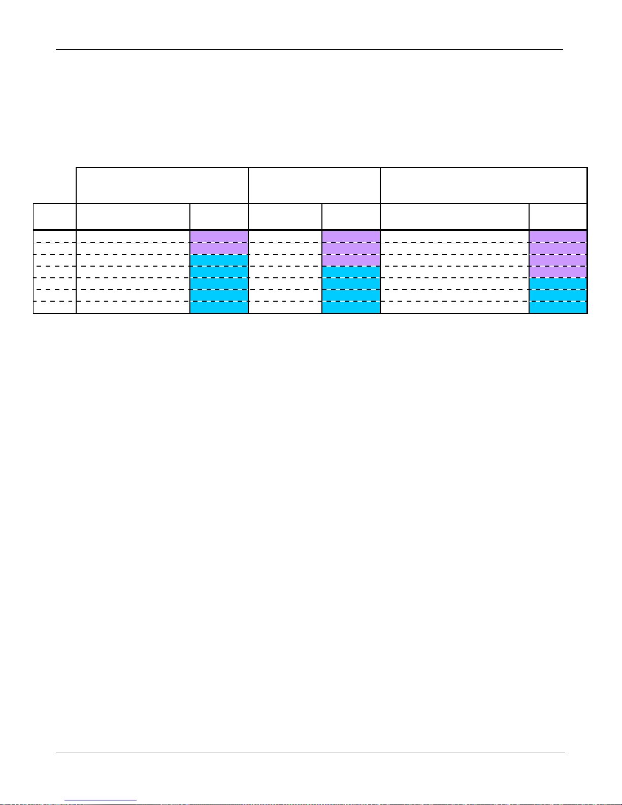
Tightening tor que for stainless steel met r ic fasteners
M3 0.9 low 0.6 low 0.2 low
M4 2.6 low 1.4 low 0.5 low
M5 5.1 medium 2.5 low 1.5 low
M6 8.7 medium 5.5 medium 2.5 low
M8 22 medium 10 medium 5 medium
M10 43 medium 24 medium 10 medium
M12 75 medium 39 medium 20 medium
Torque (Nm)
Socket Head (ISO 4762, DIN 912)
Hex Head (ISO 4014/4017, DIN
931/933)
Torque (Nm)
Torque (Nm)
Socket Set Screw (ISO 4026-4029, DIN 913-916)
-noted tig htening tor q ue values and thread locker applies fo r all fasteners unless otherwise specified in th e MAP
-app lies f o r A2/A4-70 g r ade stainless steel, plain o r non-lubr icated threads (µ
total
=0.20)
Threadlocker
strength
Threadlocker
strength
Thread
diameter
Threadlocker
strength
Socket Button Head (ISO 7380)
Socket Flat Head (DIN 7991)
Socket Low Head (DIN 7984)
APPENDIX 1: FASTENER TORQUE TABLE
C-COM Satellite Systems Inc.
 Loading...