

C-Com iNetVu 1.0 Flyaway, iNetVu 1.2 Flyaway, iNetVu 1000 Flyaway, iNetVu 1200 Flyaway User Manual
Page 1
iNetVu
®
1200/1000 Flyaway User Manual
The iNetVu® brand and logo are registered trademarks of C-COM Satellite Systems, Inc.
© Copyright 2006 C-COM Satellite Systems, Inc.
1-877-iNetVu6
www.c-comsat.com
March 22, 2012
Revision 020
Page 2

C-COM Satellite Systems Inc. Page 2 of 38
This page is intentionally left blank.
iNetVu
®
Flyaway User Manual
Page 3
C-COM Satellite Systems Inc. Page 3 of 38
Copyright © 2008. All rights reserved. C-COM Satellite Systems Inc.
This document contains information, which is protected by copyright. All rights reserved.
Reproduction, adaptation, or translation without prior written permission is prohibited, except as
followed under the copyright laws.
Both the iNetVu
Systems Inc.
®
Pentium is a registered trademark of Intel Corporation. Microsoft, Windows, Windows NT
Intel
and MapPoint are registered trademarks of Microsoft Corporation.
All other product names mentioned in this manual may be trademarks or registered trademarks of
their respective companies and are the sole property of their respective manufacturers.
®
and C-COM names and logos are registered trademarks of C-COM Satellite
iNetVu
®
Flyaway User Manual
Page 4

C-COM Satellite Systems Inc. Page 4 of 38
Table of Contents
Introduction..............................................................................................................5
1.
1.1. About This Manual..............................................................................................5
1.2. System Overview................................................................................................5
2. Physical Outline.......................................................................................................7
3. Assembly and Disassembly....................................................................................8
3.1. Assembly Procedure........................................................................................... 8
3.2. Disassembly Procedure....................................................................................15
3.3. Packaging.........................................................................................................22
4. System Connectivity..............................................................................................24
4.1. Typical Connection – PC Free..........................................................................24
4.2. Network/Web Interface Connection .................................................................. 25
4.3. Typical USB Communication Interface ............................................................. 26
4.4. System Diagram with Splitter............................................................................ 27
4.5. Router Configuration Example.......................................................................... 28
4.6. Modem Independent Setup (Stand Alone) .......................................................29
4.7. USING MODEM COM PORT ........................................................................... 30
5. iNetVu® 7000 Controller Configuration................................................................31
5.1. Software Initial Configuration and Verification .................................................. 31
6. Appendix.................................................................................................................37
6.1. Appendix 1: Default Limits and Configuration Data Tables .............................. 38
Proprietary Notice: This document contains information that is proprietary and
confidential to C-COM Satellite Systems, Inc., and is intended for internal and or
C-COM Satellite Systems Inc. authorized partners use only. No part of this
document may be copied or reproduced in any way, without prior written
permission of C-COM Satellite Systems, Inc.
iNetVu
®
Flyaway User Manual
Page 5
C-COM Satellite Systems Inc. Page 5 of 38
1. Introduction
1.1. About This Manual
This manual explains the iNetVu
electronic version of this manual is included on the iNetVu
system.
1.2. System Overview
Equipped to work with the iNetVu
easily assembled, rugged and reliable product for automatic satellite acquisition. This
lightweight antenna is a rapidly deployable unit that is ideal for applications that require
satellite communication over Ku-Band. The Flyaway empowers users with the ability to
stop anywhere there exists satellite coverage and access Internet at broadband speeds.
The 1.2M Flyaway System comes with a protective case that has been designed to be
airline checkable. Without the use of any tools, the Flyaway could be field assembled
and operational in less than 10 minutes by one person.
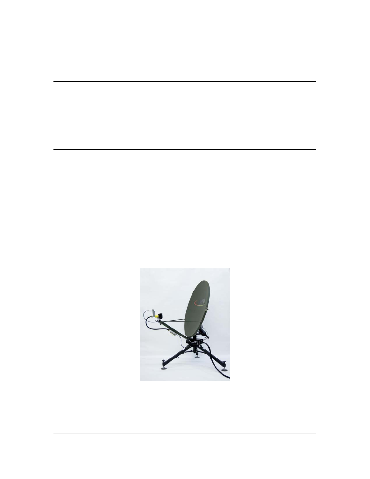
Fig. 1: iNetVu® 1200/1000 Flyaway
®
Flyaway System Installation and Operation. An
®
7000 Controller, the iNetVu® Flyaway antenna is an
®
CD that came with your
iNetVu
®
Flyaway User Manual
Page 6

C-COM Satellite Systems Inc. Page 6 of 38
The iNetVu® Flyaway system offers the following additional capabilities and features:
3-Axes DC motor drive system
Highly reliable linear actuator to control elevation
Satellite acquisition within 5 minutes (under normal operating conditions)
Compatible with any configured satellite over the Ku Band
Fully automatic, software controlled satellite acquisition
Optimized signal reception and transmission
Self-calibrating and tuning after satellite acquisition
Stand Alone – Satellite Acquisition via DVB (modem independent)
Integrated with some of the leading satellite service providers available.
Easily assembled, light-weight carry gear
iNetVu
®
Flyaway User Manual
Page 7
C-COM Satellite Systems Inc. Page 7 of 38
2. Physical Outline
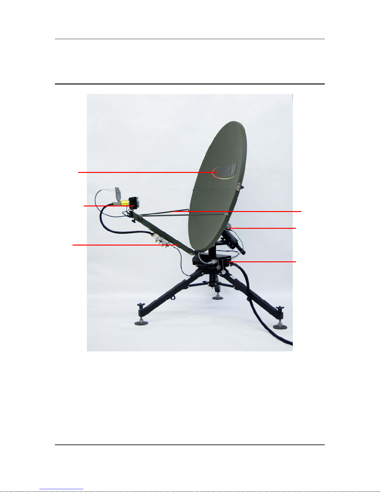
2-piece
Detachable reflector
Polarization
Assembly & Motor
Feed Arm
Feed Ho
rn
Feed Arm Struts
Elevation Motor
Azimuth Motor &
Gear
iNetVu
®
Flyaway User Manual
Page 8
C-COM Satellite Systems Inc. Page 8 of 38
3. Assembly and Disassembly
3.1. Assembly Procedure
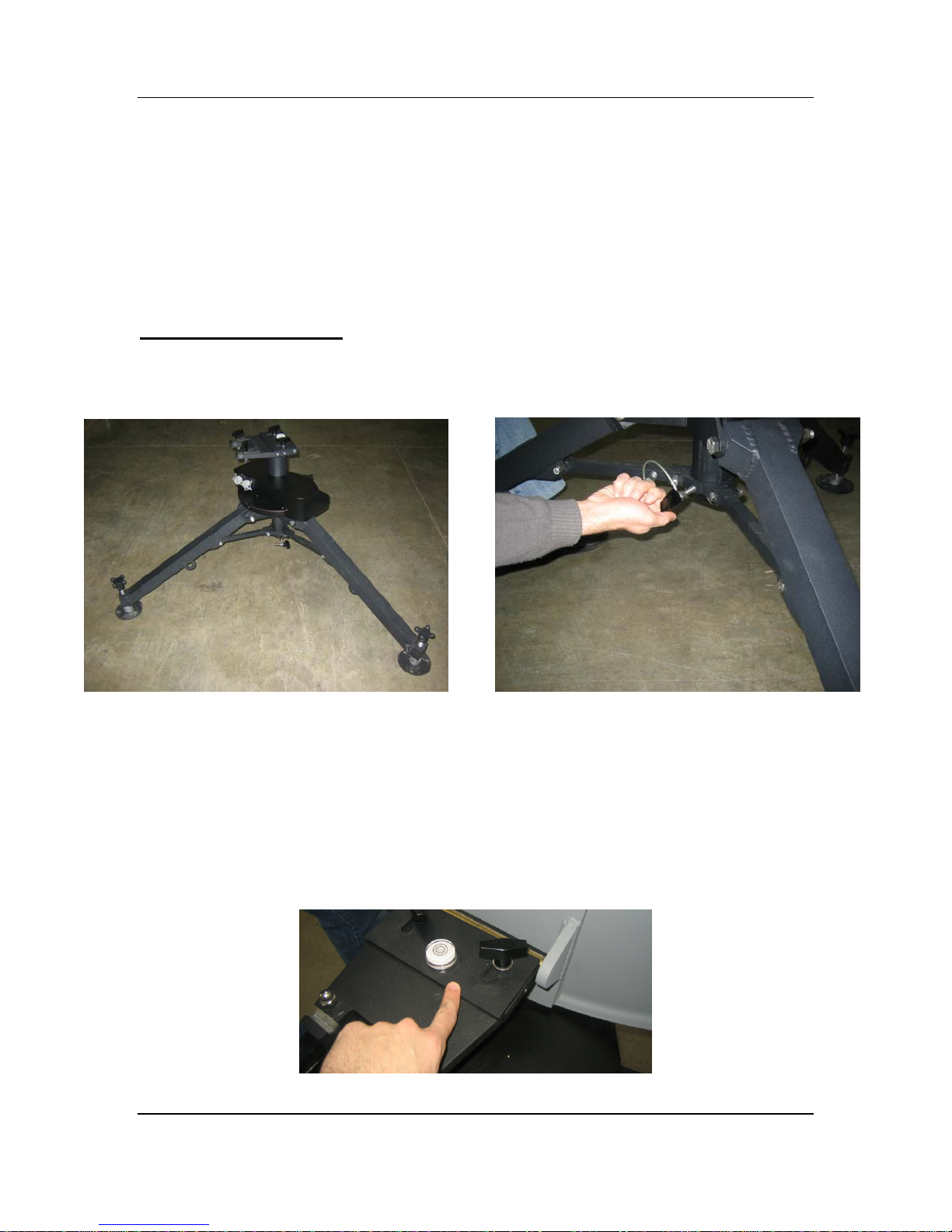
Support Stand Assembly
1) Unfold the tripod assembly and lock the leg assemblies into place with the T-Handled
threaded knob as pictured below.
2) Unlock the two (2) T-Handled threaded knobs gripping the lock plate above the pivot
location of the lower reflector assembly. Lift the lock plate, and slide the lower
reflector assembly into the pivot as depicted in the figure below.
iNetVu
®
Flyaway User Manual
Page 9
C-COM Satellite Systems Inc. Page 9 of 38
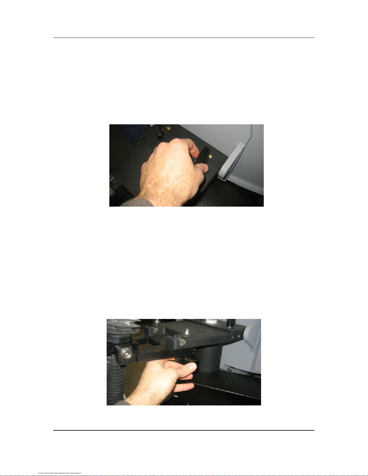
3)
Push the lock plate towards the lower reflector assembly, and lock the two (2)
threaded knobs.
4)
Attach the elevation motor assembly to the tripod assembly by sliding the elevation
bracket between the tripod assembly and the washers of the T-handled threaded
knobs. You may have to loosen the knobs before insertion.
When the elevation bracket is locked into place, tighten the two (2) T-handled
threaded knobs such that the washer firmly grips the bracket to the tripod assembly.
Facing the back of the reflector, the elevation motor should be facing left.
Note: Avoid
the bellows when
handling the elevation
motor assembly.
twisting
iNetVu
®
Flyaway User Manual
Page 10
C-COM Satellite Systems Inc. Page 10 of 38
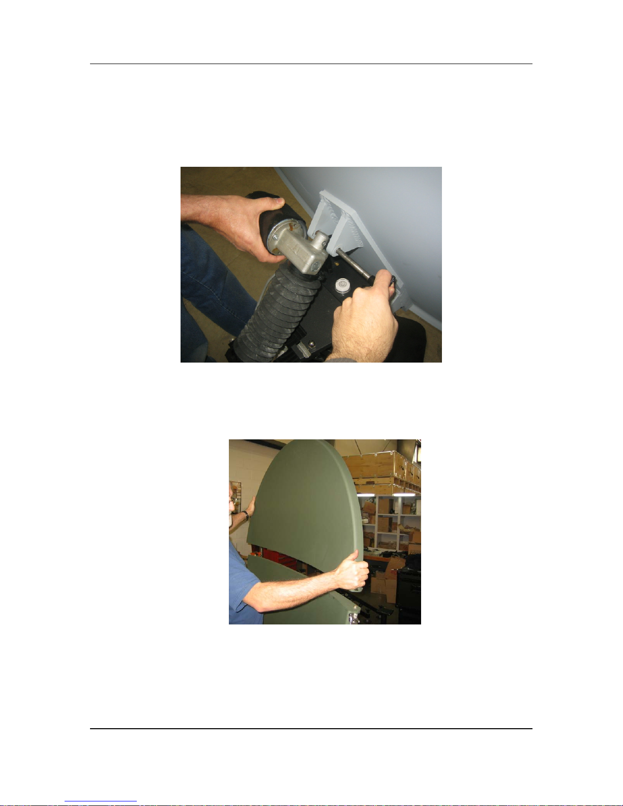
5)
Lock the elevation motor assembly into place by lining the mounting holes between
the lower reflector assembly and the elevation motor assembly and inserting the
quick release pin as depicted below.
6) Attach the upper reflector assembly to the lower reflector assembly making sure the
dowel pins fit securely in place.
iNetVu
®
Flyaway User Manual
Page 11
C-COM Satellite Systems Inc. Page 11 of 38
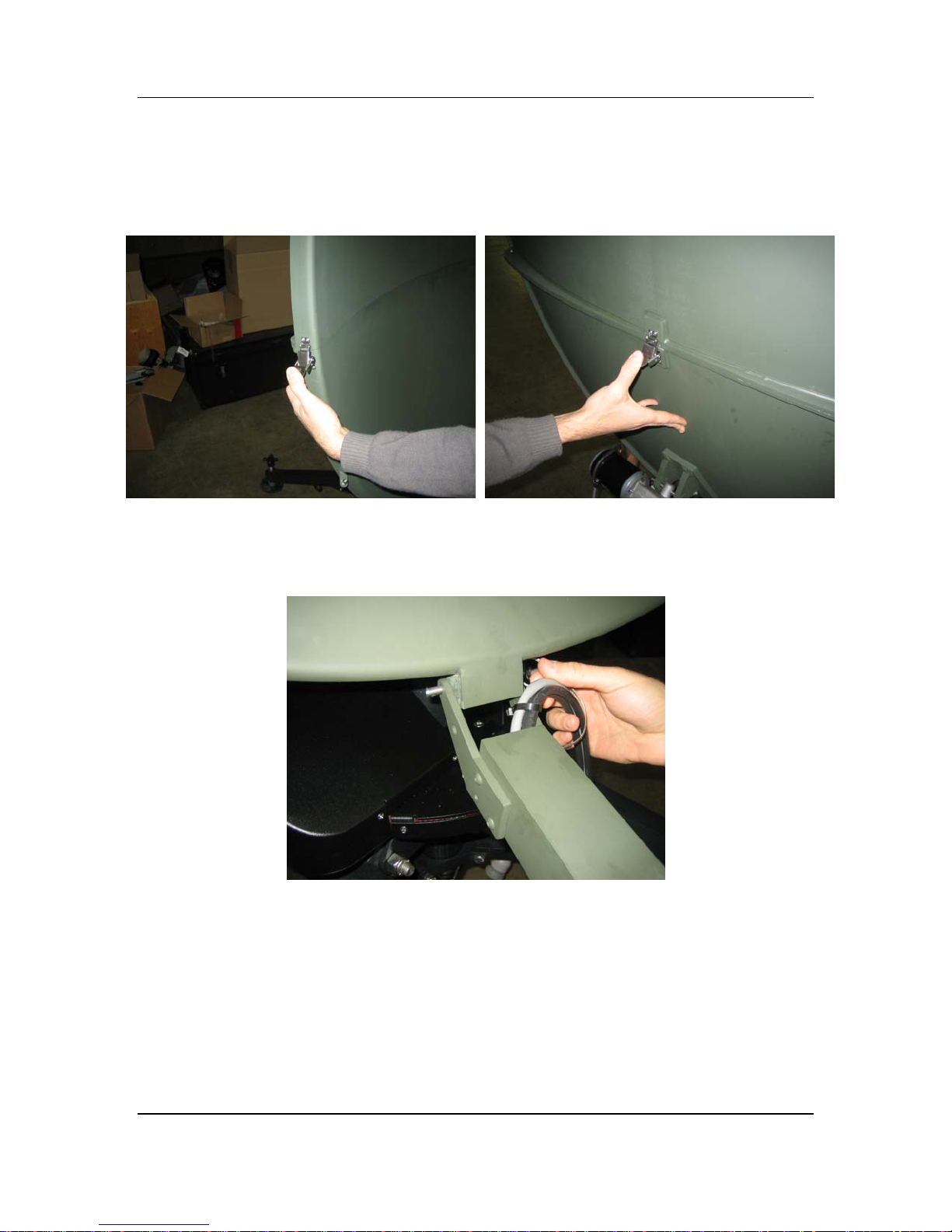
)
Lock the reflectors together using the three (3) latches on the back and on both sides 7
of the reflector.
) Attach the feed arm to the lower reflector by lining the mounting holes between the
8
feed arm and the attachment block of the lower reflector and inserting the pin.
iNetVu
®
Flyaway User Manual
Page 12
C-COM Satellite Systems Inc. Page 12 of 38
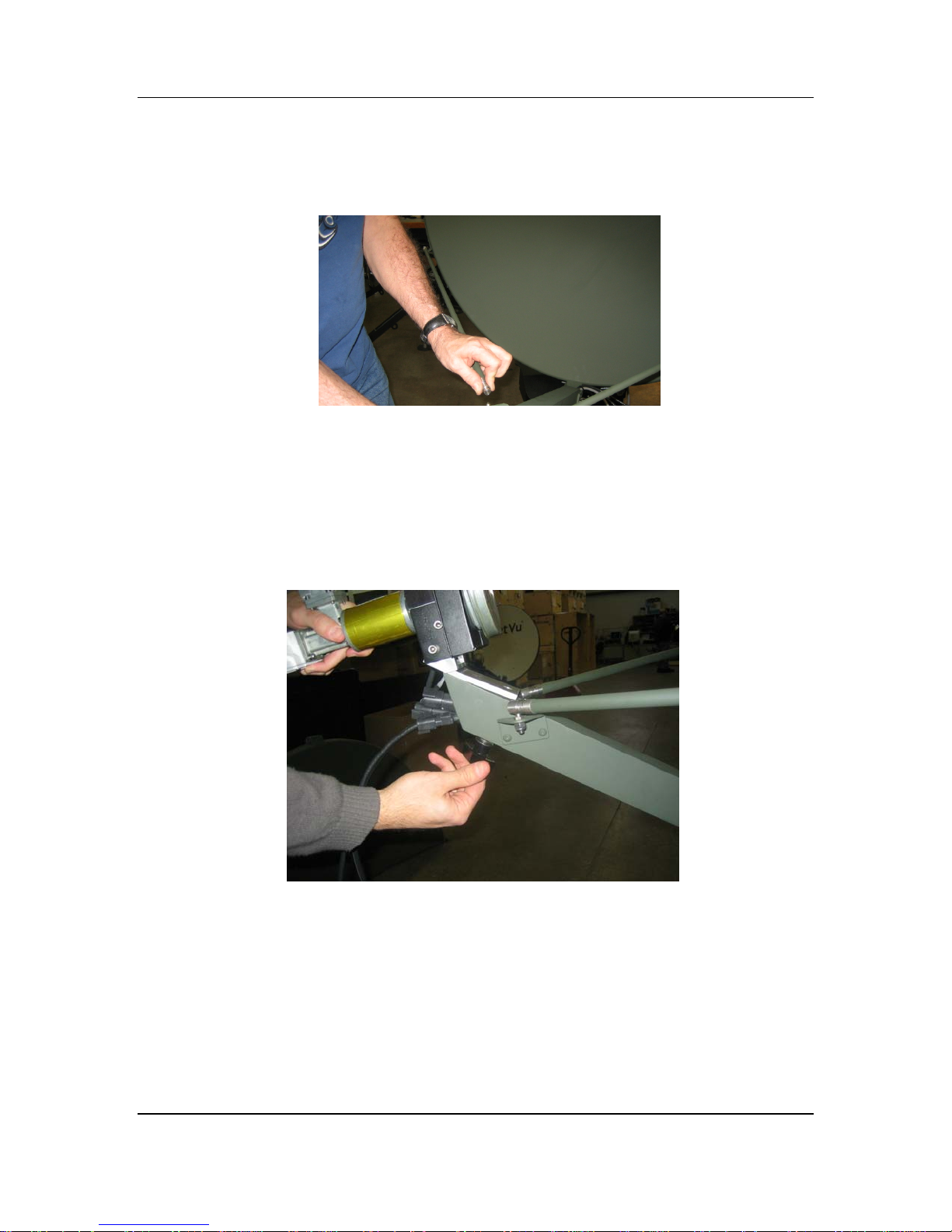
) Snap the feed arm strut to the feed arm and reflector sides by retracting the spring-9
loaded barrel on the ball socket end fitting and snapping it into place
0) If the polarization assembly is not already attached to the feed arm, attach the
1
feed polarization assem
bly to the feed arm assembly, and secure it with the T-
Handled threaded knob located on the bottom side of the feedarm.
iNetVu
®
Flyaway User Manual
Page 13
C-COM Satellite Systems Inc. Page 13 of 38
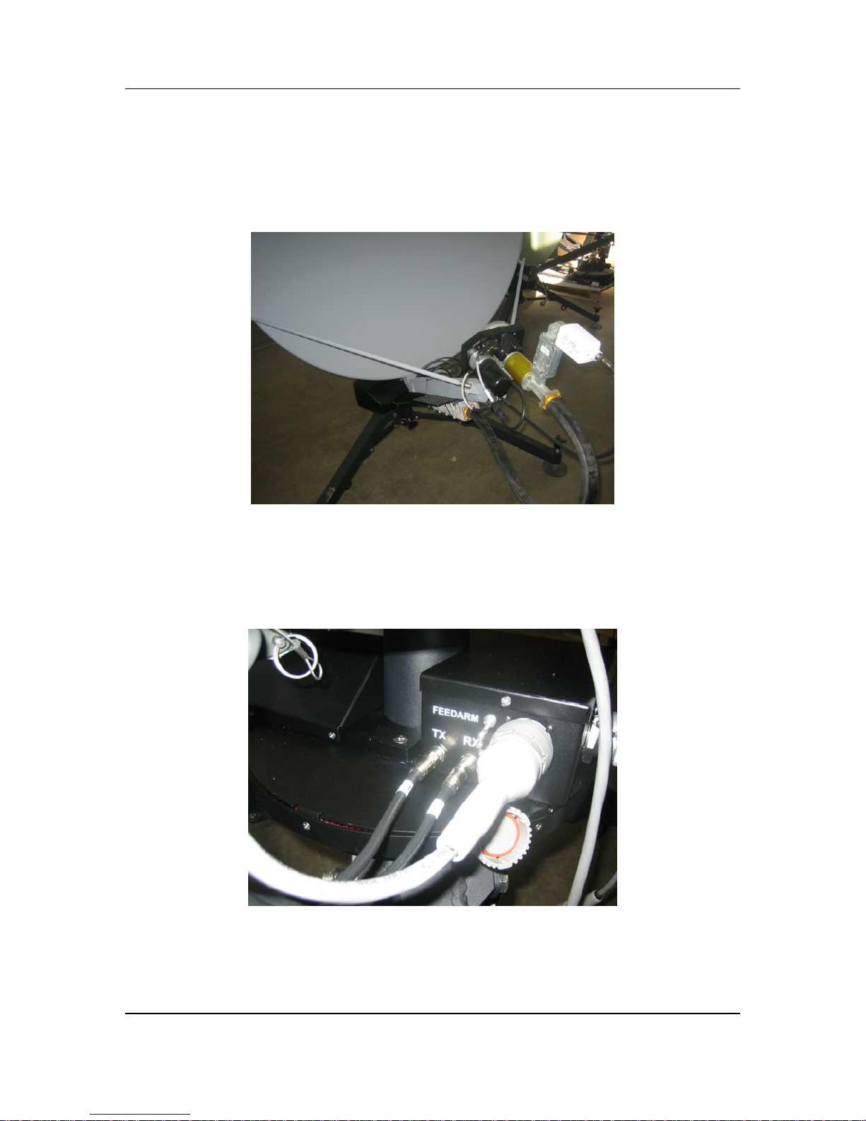
1) Connect the RX Cable running through the feedarm to the LNB, and the TX Cable to
1
the BUC.
2) Connect the internal Motor/Sensor cable, as well as the labelled RX, and TX coax
1
cables running through the bottom of the feedarm to their corresponding inputs on
the connector plate labelled “FEEDARM” on the platform.
iNetVu
®
Flyaway User Manual
Page 14
C-COM Satellite Systems Inc. Page 14 of 38
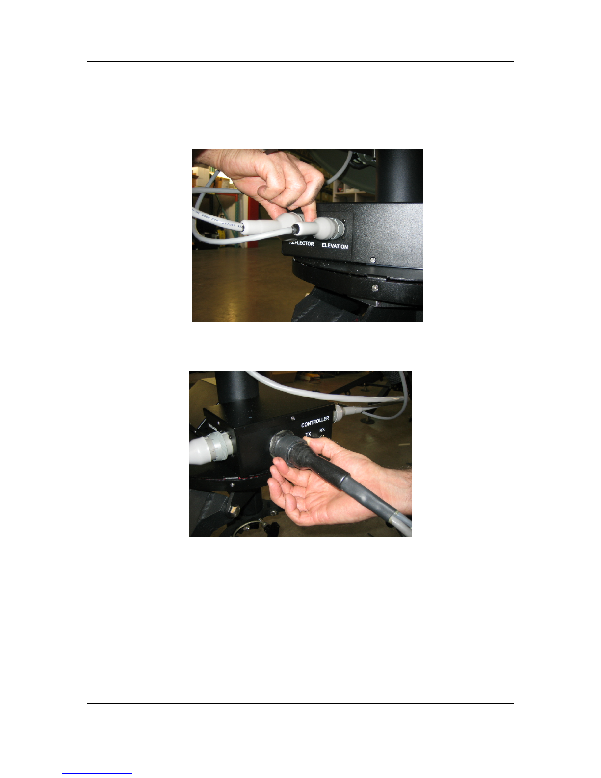
13) Connect the reflector (inclinometer) and elevation (elevation motor) cables to the
area on the
connector plate labelled “REFLECTOR” and “ELEVATION”. The cables
only fit in one direction.
14) Insert the external Motor/Sensor Cable, RX and TX coax cables into the proper
location on the connector plate labelled “CONTROLLER”.
15) Follow the “Installing BUC with the Universal Mounting Clamp kit” for mounting the
BUC onto the mounting plate of the feed arm.
16) See section 4) for controller connectivity based on your desired connection
preferences.
17) Congratulations, you have successfully assembled the iNetVu
®
Flyaway System!
iNetVu
®
Flyaway User Manual
Page 15
C-COM Satellite Systems Inc. Page 15 of 38
3.2. Disassembly Procedure
WARNING: ENSURE THE PLATFORM IS STOWED BEFORE DISASSEMBLY
Disconnecting Cables
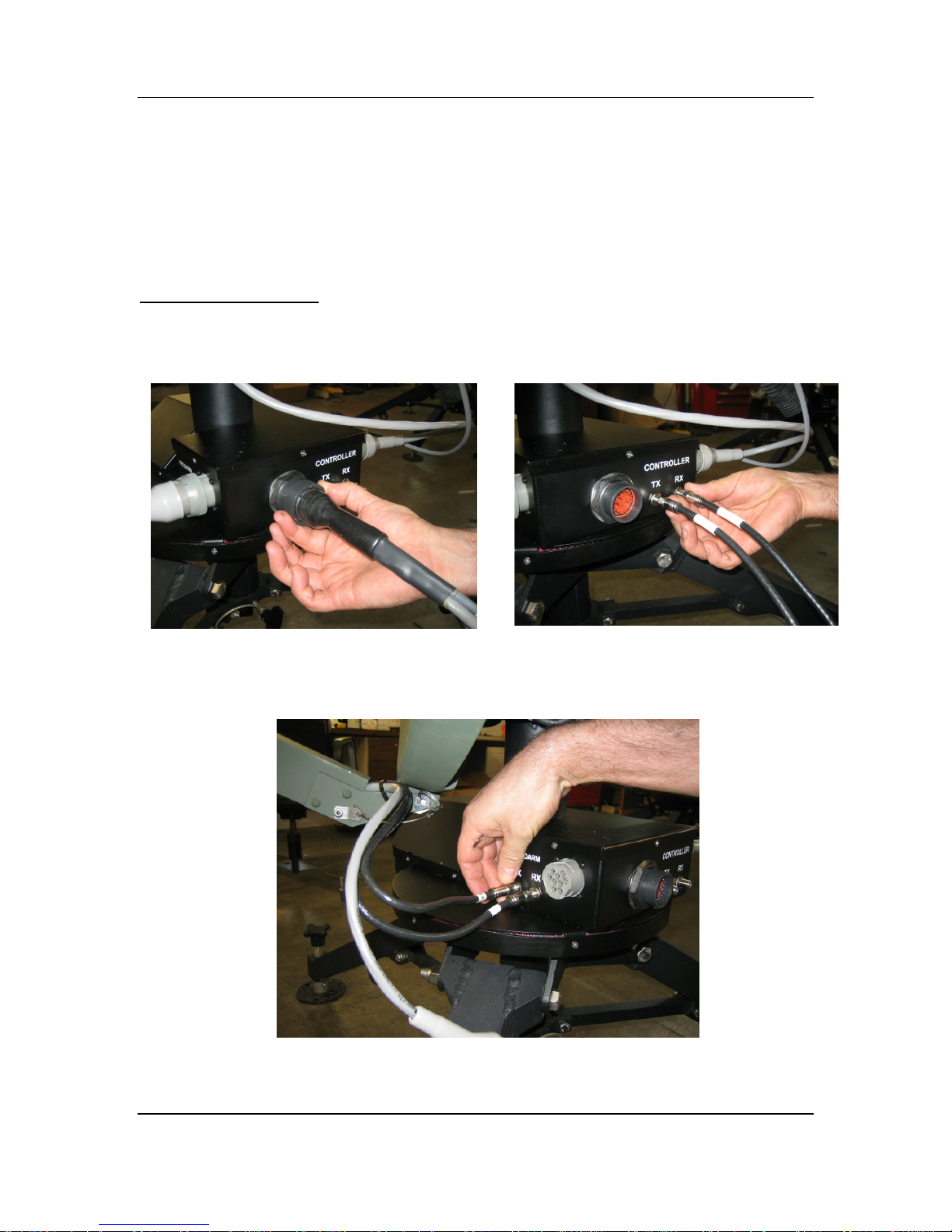
1) Disconnect the External Sensor/Motor cable, RX, and TX coax cables from the
connector plate labelled CONTROLLER on the platform.
2)
Disconnect the internal Motor/Sensor cable, RX, and TX coax cables from the
connector plate labelled “FEEDARM” on the platform.
iNetVu
®
Flyaway User Manual
Page 16
C-COM Satellite Systems Inc. Page 16 of 38
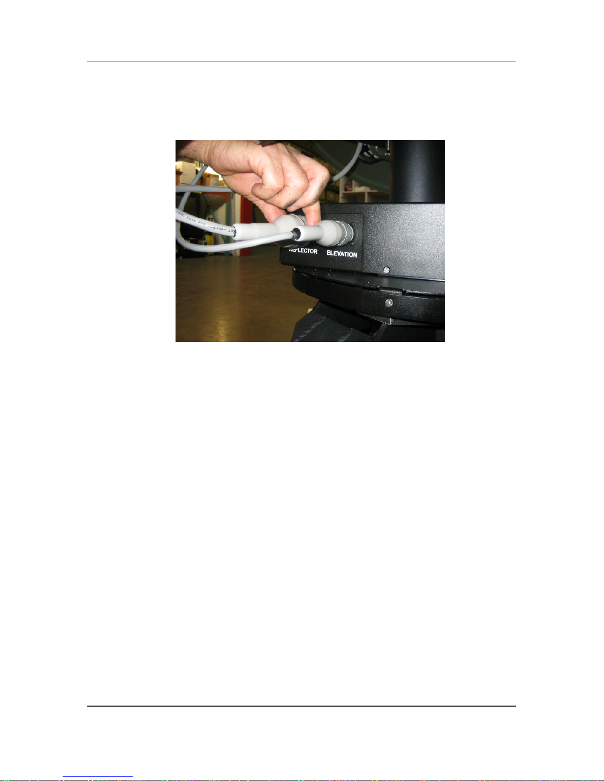
3) Disconnect the cables from the connector plate labelled “REFLECTOR” and
“ELEVATI
ON”
4)
Disconnect the RX and TX Coax cables attached to the BUC and LNB
iNetVu
®
Flyaway User Manual
Page 17
C-COM Satellite Systems Inc. Page 17 of 38
Polarization and Feed Arm Assembly Removal
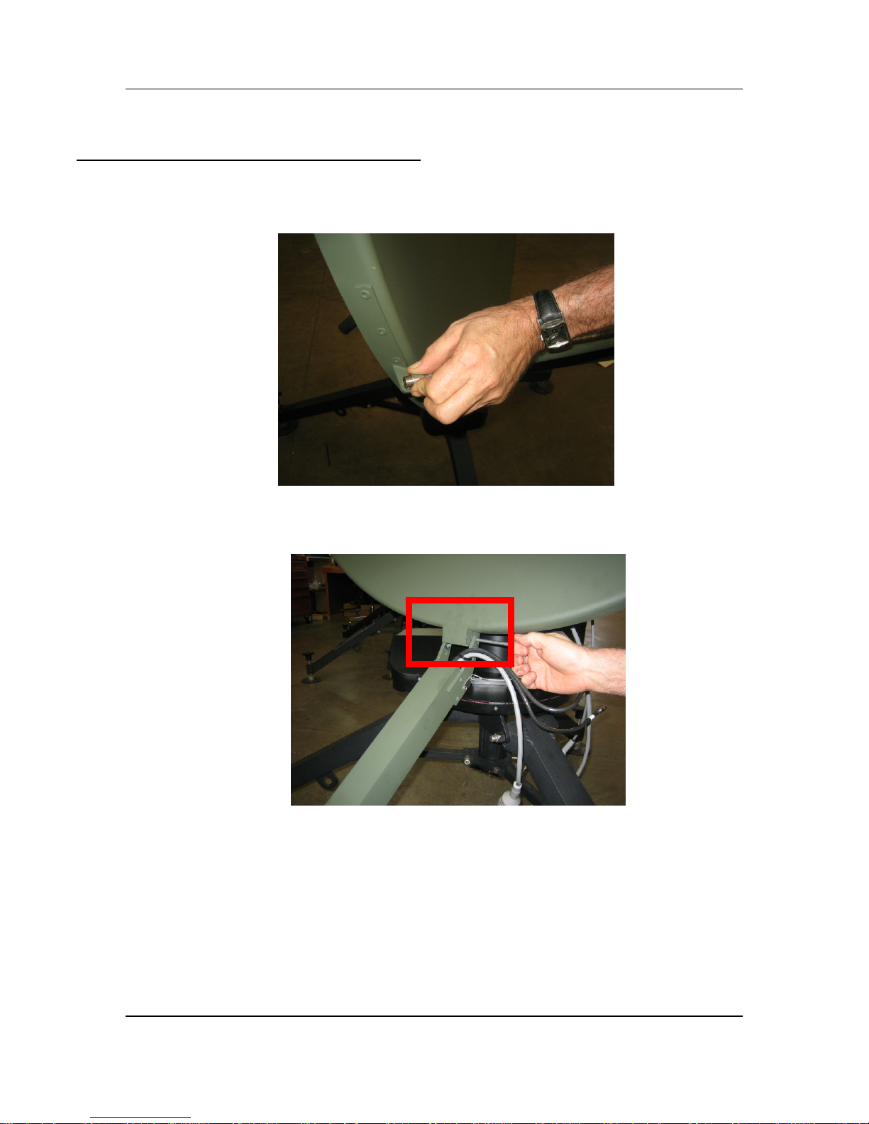
5) Detach the two (2) feedarm struts on both ends by retracting the spring-loaded
barrel on the ball socket end fitting and remove.
6)
Gently lower the feedarm, and remove the supporting pin to detach the feedarm
from the reflector.
iNetVu
®
Flyaway User Manual
Page 18
C-COM Satellite Systems Inc. Page 18 of 38
Reflector a
nd Elevation Motor Assembly Removal
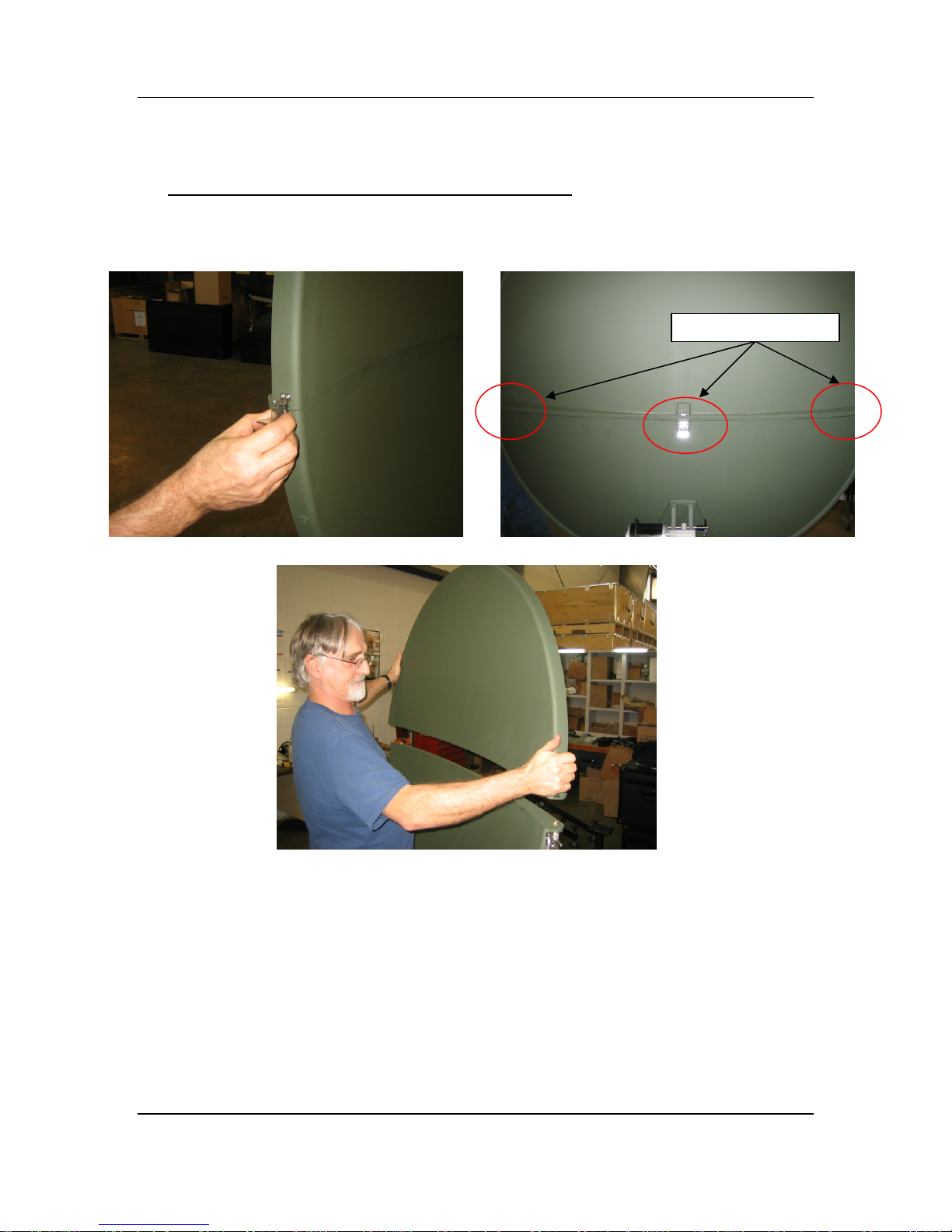
7) Unhook the three (3) latches holding the two-piece reflector together, and detach
the top reflector assembly.
iNetVu
®
Flyaway User Manual
Page 19

C-COM Satellite Systems Inc. Page 19 of 38
8)
Remove the Quick Release T-Pin attaching the elevation motor assembly to the
reflector; ensure to hold the lower reflector assembly during removal of the t-pin.
9) Unlock the two (2) T-Handle threaded knobs securing the elevation motor
assembly to the tripod assembly, and slide the elevation bracket out.
iNetVu
®
Flyaway User Manual
Note: Avoid
twisting
the bellows covering
the actuator when
handling the
elevation motor
assembly.
Page 20
C-COM Satellite Systems Inc. Page 20 of 38
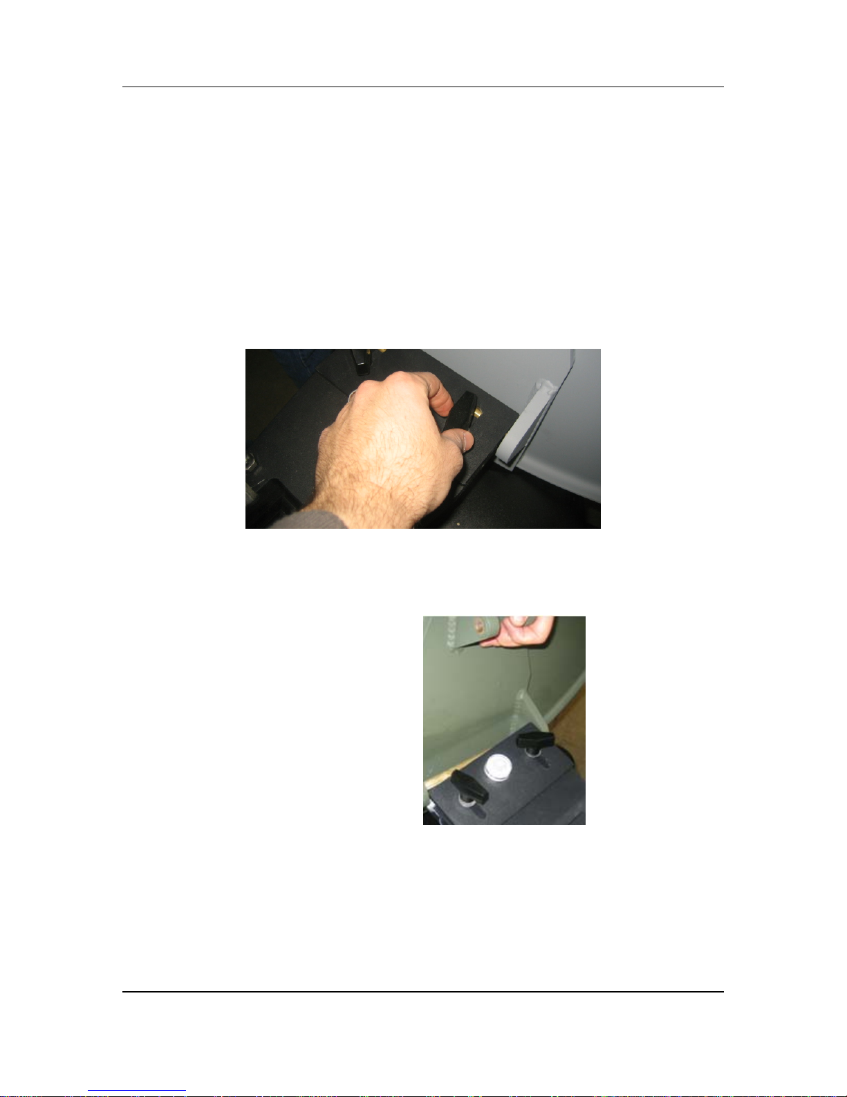
10)
Unlock the two (2) T-Handle threaded knobs attaching the reflector to the tripod
assembly. Ensure to hold the bottom reflector assembly while loosening the
knobs.
11)
Slide the reflector from under the lock plate, and remove from the base tripod
assembly.
iNetVu
®
Flyaway User Manual
Page 21
C-COM Satellite Systems Inc. Page 21 of 38
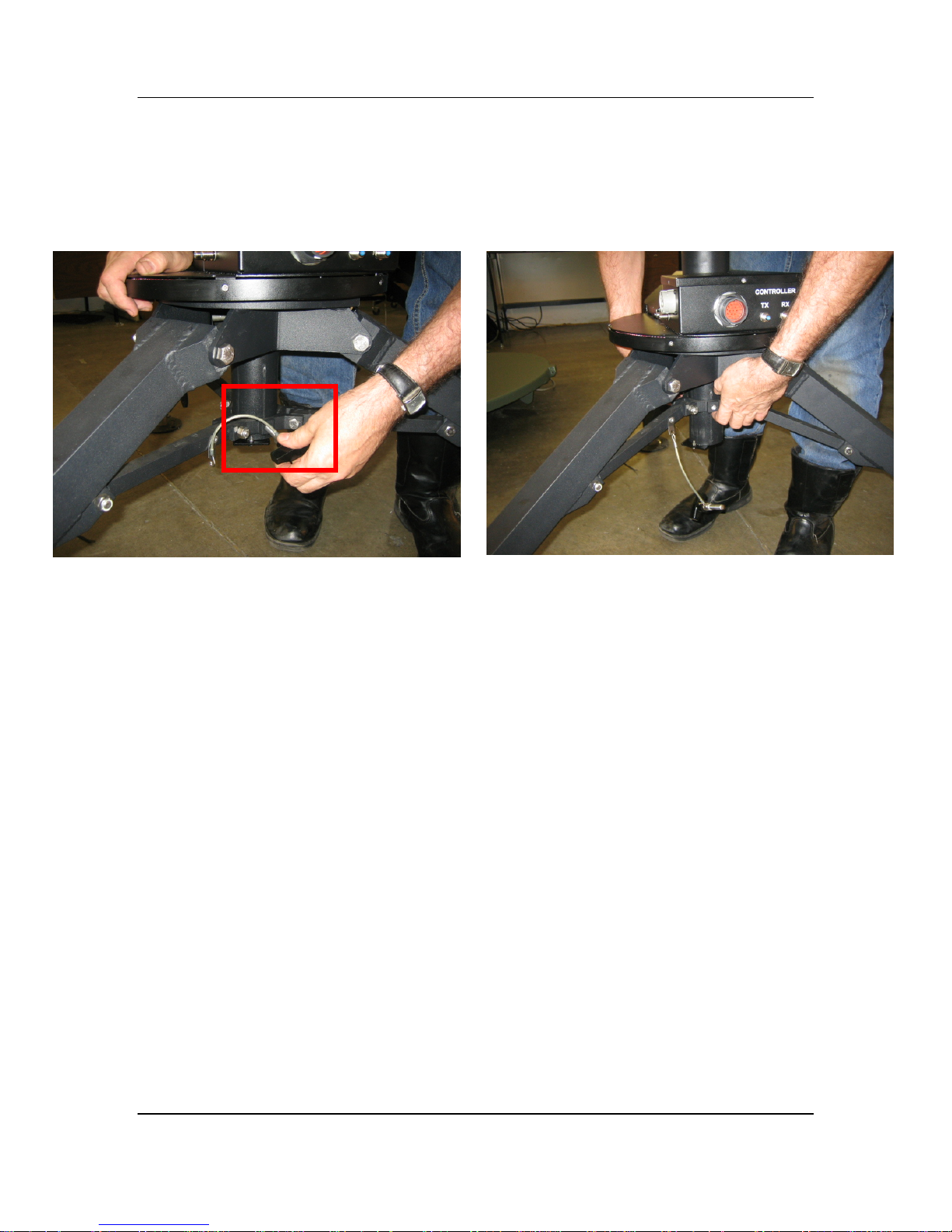
12)
Loosen the T-Handle threaded knob locking the leg assemblies, and fold in the
tripod assembly.
iNetVu
®
Flyaway User Manual
Page 22
C-COM Satellite Systems Inc. Page 22 of 38
3.3. Packaging
To avoid damaging hardware components during travel and handling, this section will
outline the ideal procedure of packaging the iNetVu
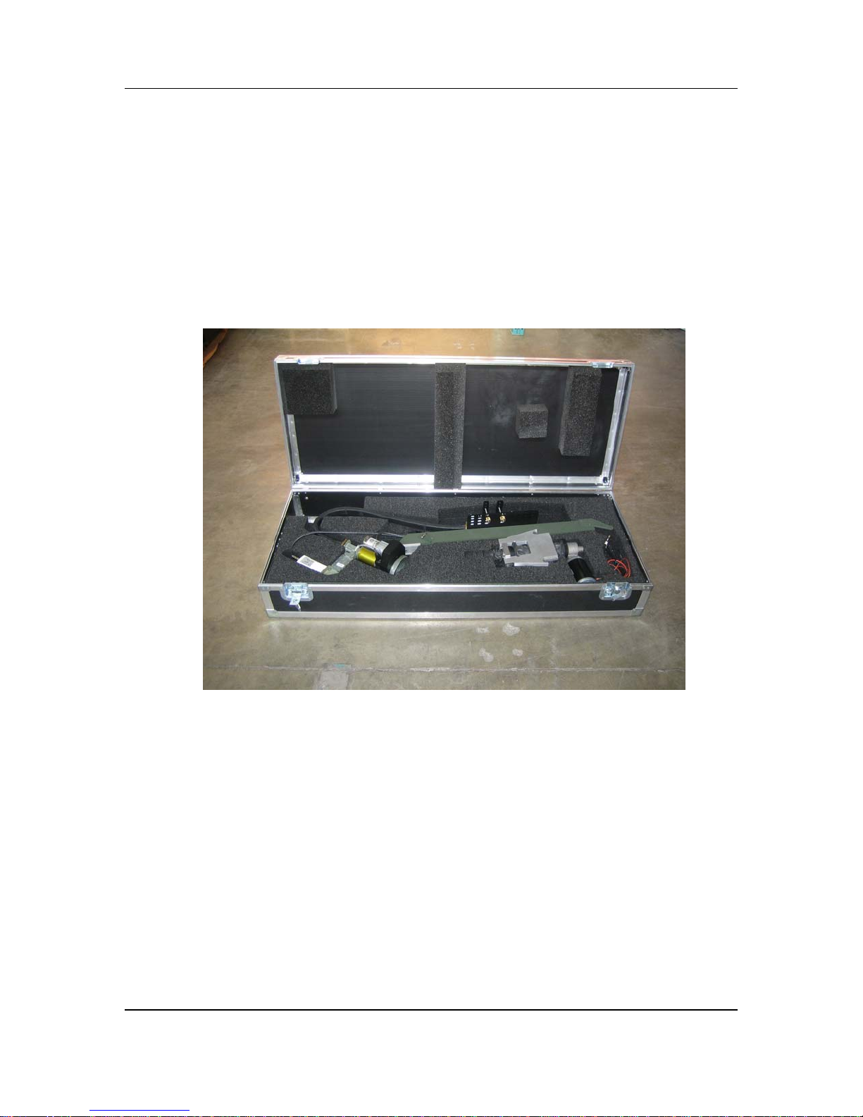
1) Place the feed boom and elevation assemblies into the feed case as depicted in
the picture below.
®
1.2/1.0 Flyaway Antenna systems.
iNetVu
®
Flyaway User Manual
Page 23
C-COM Satellite Systems Inc. Page 23 of 38
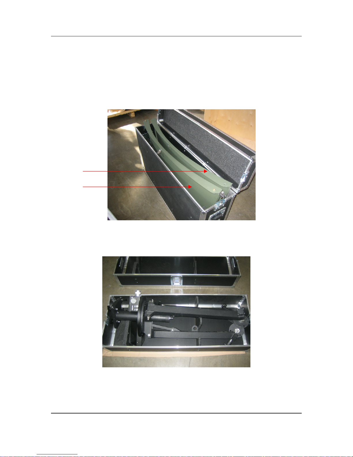
2) Insert the bottom and top reflector assemblies into the reflector case as depicted
in the figure
Place the top reflector assembly in the section of the case closest to the pivot
joints of the top cover, facing inwards.
Top Reflector Assembly
Bottom Reflector Assembly
below.
3)
Place the tripod assembly into the tripod case as depicted in the picture below.
4) Congratulations you have successfully packaged the iNetVu
®
Flyaway System.
iNetVu
®
Flyaway User Manual
Page 24
C-COM Satellite Systems Inc. Page 24 of 38
Cable
4. System Connectivity
The iNetVu
®
1200/1000 Flyaway Antenna has been built to operate with the iNetVu®
7000 Controller. The typical connection configuration for each service will be the same
regardless of the Satellite Modem / VSAT. However, the configuration parameters for
Satellite Modem / VSAT Communication will differ depending on service. The user may
select the connection that corresponds to his/her preferred system setup prior to
configuration.
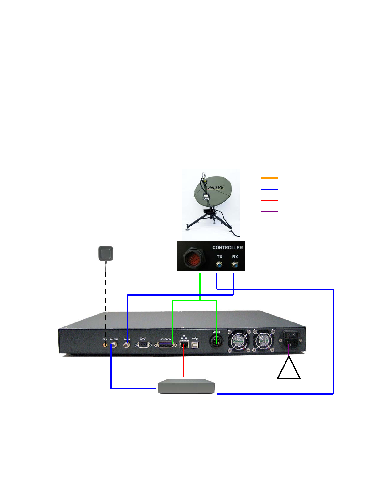
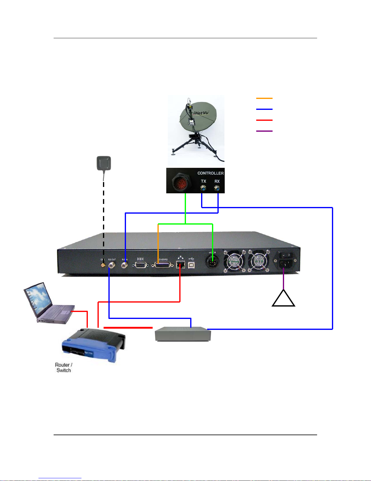
4.1. Typical Connection – PC Free
GPS
Antenna
Combined Sensor and Motor
RG6 Coaxial Cable
Network Cable
Power Cable
COMBINED SENSOR
AND MOTOR
CABLE
TX
RX
RX
Network Cable
RX
Satellite Modem / VSAT
90 - 264VAC
Fig. 2: iNetVu® 7000 Controller PC Free Connection Configuration
iNetVu
®
Flyaway User Manual
!
Page 25
C-COM Satellite Systems Inc. Page 25 of 38
Cable
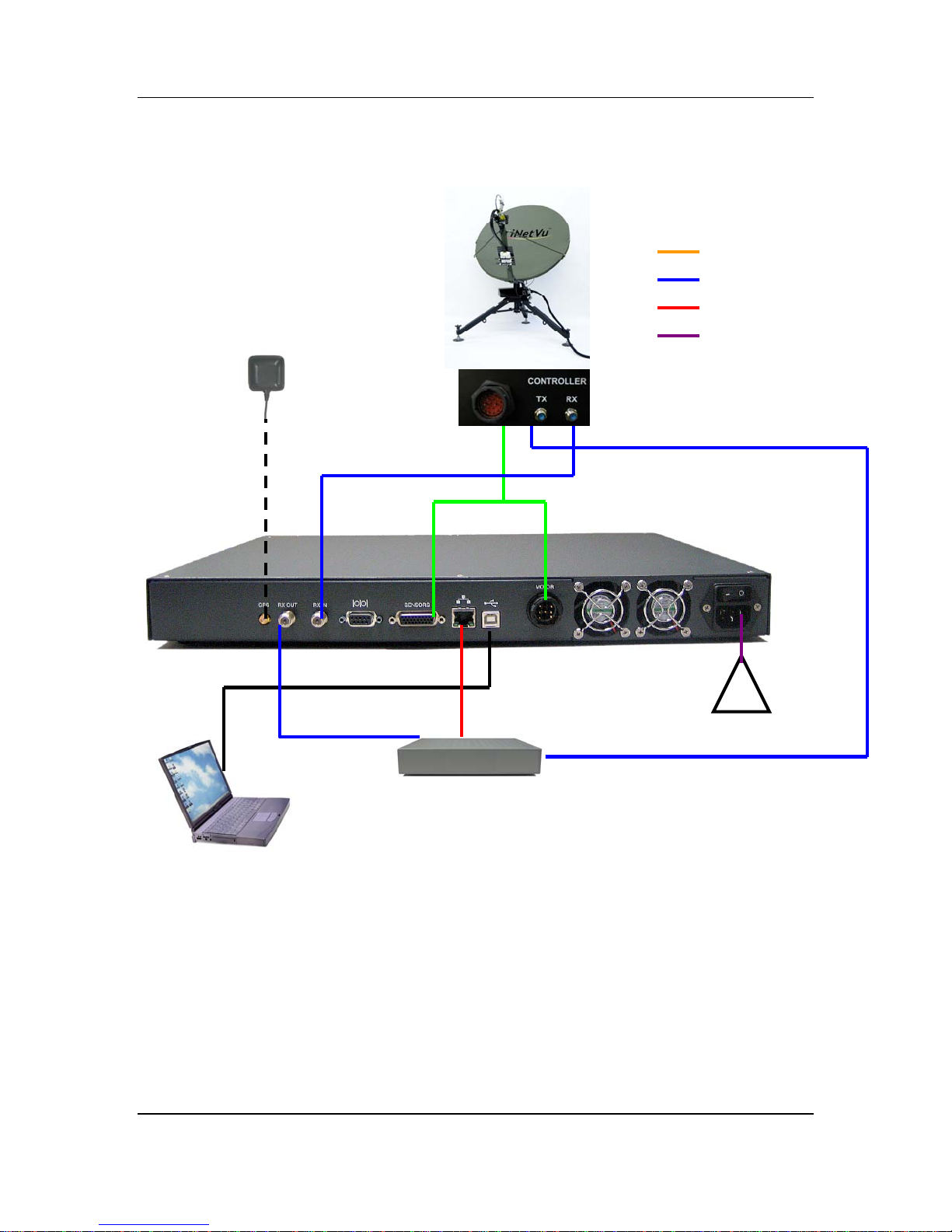
4.2. Network/Web Interface Connection
iNetVu® Flyaway
Platform
GPS
Antenna
COMBINED MOTOR
AND SENSOR
CABLE
TX
RX
Combined Sensor and Motor
RG6 Coaxial Cable
Network Cable
Power Cable
RX
Satellite Modem / VSAT
RX
TX OUT
90 - 264VAC
Fig. 3: iNetVu® 7000 Controller Typical Connection Configuration
iNetVu
®
Flyaway User Manual
Page 26
C-COM Satellite Systems Inc. Page 26 of 38
Cable
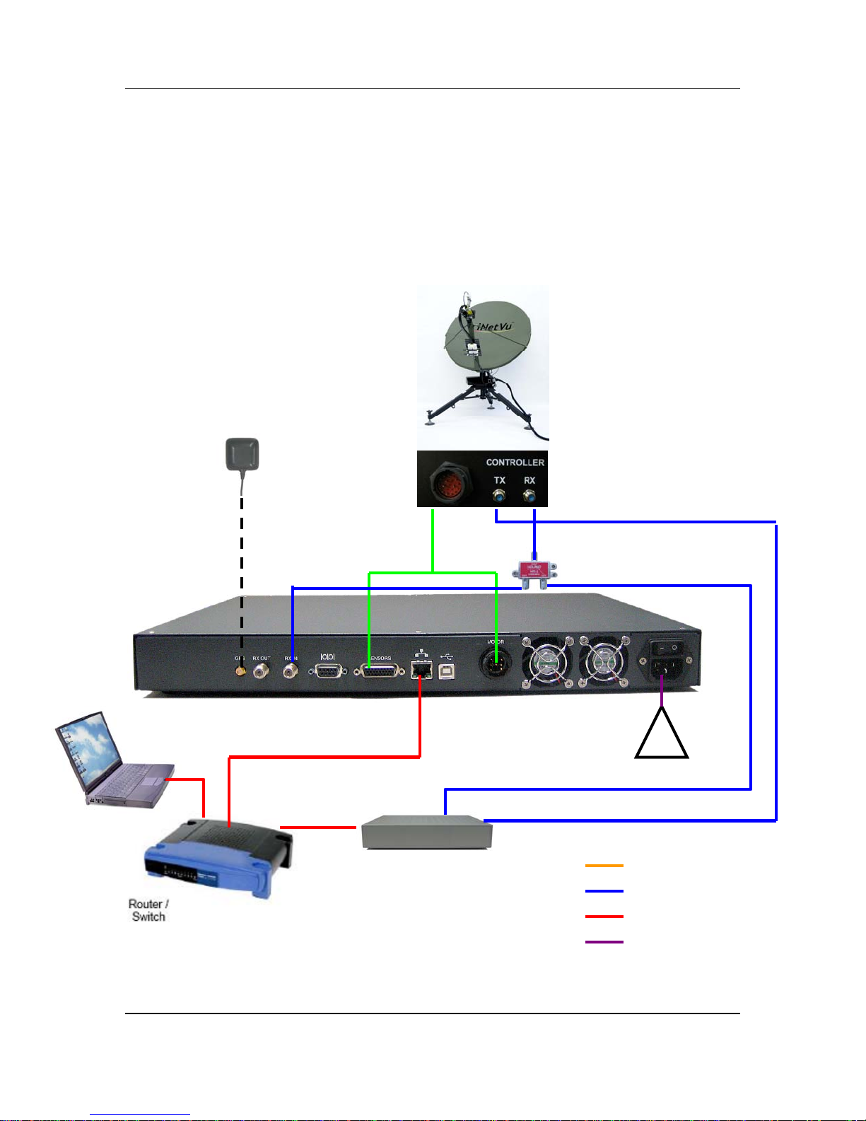
4.3. Typical USB Communication Interface
GPS
Antenna
COMBINED MOTOR AND
SENSOR
CABLE
TX
RX
Combined Sensor and Motor
RG6 Coaxial Cable
Network Cable
Power Cable
USB Cable
RX
Network Cable
90 - 264VAC
TX OUT
!
Satellite Modem / VSAT
Fig. 4: USB Configuration Interface
iNetVu
®
Flyaway User Manual
Page 27
C-COM Satellite Systems Inc. Page 27 of 38
Cable
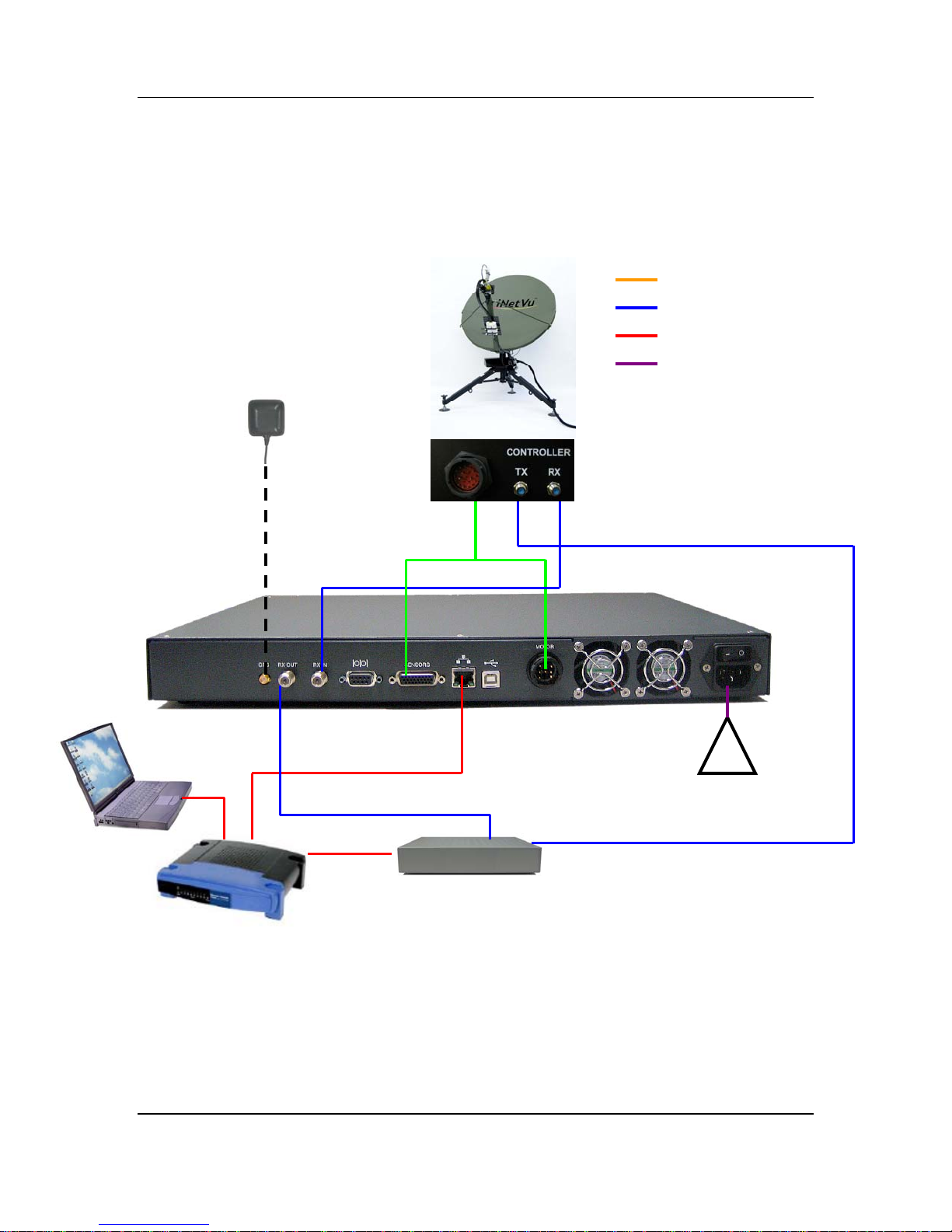
4.4. System Diagram with Splitter
*Please Note: Using a splitter is optional. If the user does not wish to power the LNB
from the Controller, a splitter must be used such that power is passed to the LNB from
the VSAT Modem (or alternate power source).
iNetVu® Flyaway
Platform
GPS
Antenna
COMBINED MOTOR
AND SENSOR
CABLE
RX
*If the splitter option is
used, ensure the LNB
Power is disabled in the
7000 Controller. (See
section 7.2.2.1 in the 7000
User Manual – “LNB
Power” for more detail)
TX
RX
*The user may also setup the system with a splitter without
PC (must configure from LCD) or through USB interface
instead of using Ethernet to interface between the PC and the
7000 Controller.
Satellite Modem / VSAT
iNetVu
®
Flyaway User Manual
!
RX
TX OUT
a
90 - 264VAC
Combined Sensor and Motor
RG6 Coaxial Cable
Network Cable
Power Cable
Page 28
C-COM Satellite Systems Inc. Page 28 of 38
Cable
4.5. Router Configuration Example
iNetVu® Flyaway
Platform
GPS
Antenna
MOTOR CONTROL
AND SENSOR
CABLE
TX
RX
Combined Sensor and Motor
RG6 Coaxial Cable
Network Cable
Power Cable
PC: DHCP
OR
Static:
IP: 192.168.1.
SUB: 255.255.255.0
GW: 192.168.1.1
2
Router
Router:
WAN IP: 70.232.
SUB: 255.255.255.0
LAN IP: 192.168.1.1
SUB: 255.255.255.0
247.50
WAN Port
iNetVu
7000 CT
OR
Static:
IP: 192.168.1.3
SUB: 255.255.255.0
GW: 192.168.1.1
RX IN
Satellite Modem / VSAT
Modem Example:
70.232.247.49
®
Flyaway User Manual
RL: DHCP
!
90 - 264VAC
TX OUT
Page 29
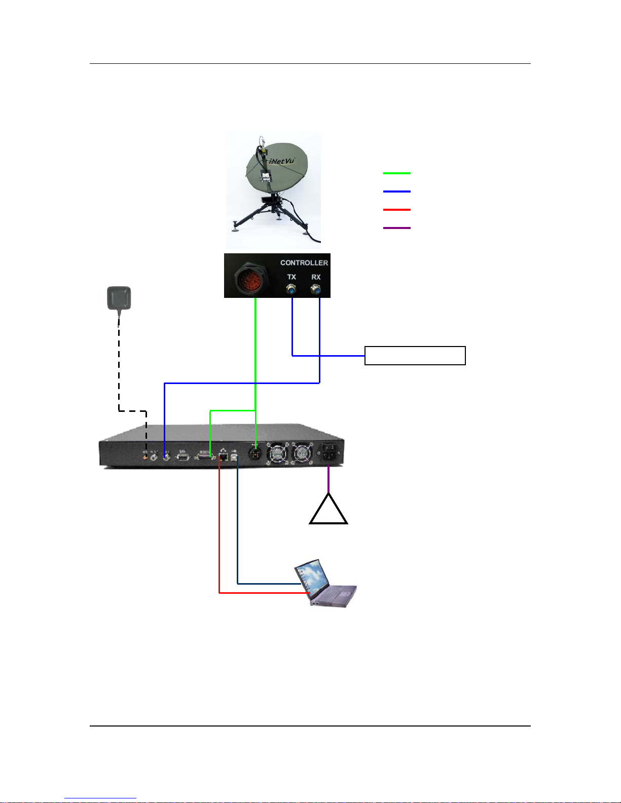
C-COM Satellite Systems Inc. Page 29 of 38
Cable
4.6. Modem Independent Setup (Stand Alone)
GPS
Antenna
RX IN
COMBINED
MOTOR AND
SENSOR
CABLE
RX TX
Transmit Source
Combined Sensor and Motor
RG6 Coaxial Cable
Network Cable
Power Cable
ETHERNET
CABLE
*NOTE: The user may use
a USB Cable OR a Network
Cable to interface between
the 7000 Controller and
the PC/Notebook. If the
user does not wish to use
a PC/Notebook, NO Cable
is required and the user
must configure the 7000
Controller from the LCD
Interface.
OR
USB
CABLE
iNetVu
1
2VDC POWER
CABLE
90 - 264VAC
®
Flyaway User Manual
Page 30
C-COM Satellite Systems Inc. Page 30 of 38
Cable
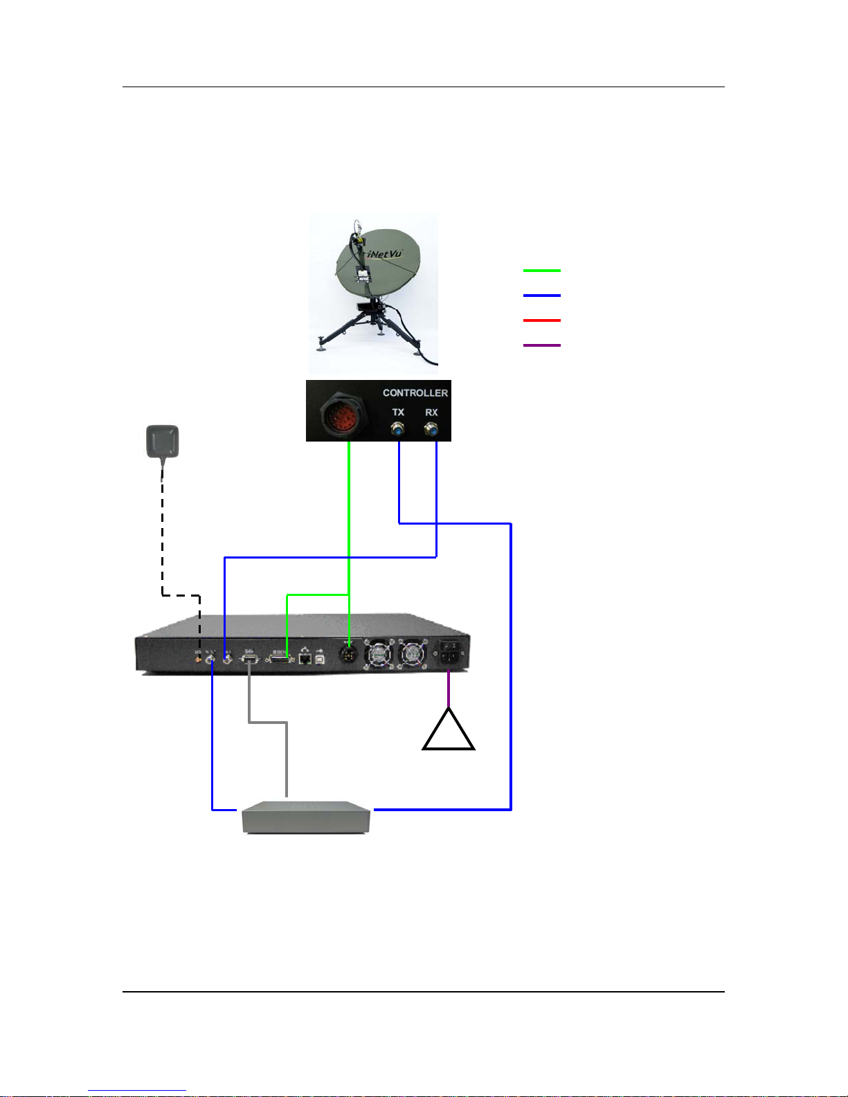
4.7. USING MODEM COM PORT
GPS
Antenna
RX IN
COMBINED
MOTOR AND
SENSOR
CABLE
RX TX
Combined Sensor and Motor
RG6 Coaxial Cable
Network Cable
Power Cable
RX OUT
SAT IN
PC Serial
Interface +
NULL MODEM
COM
PORT
Satellite Modem / VSAT
12VDC POWER
CABLE
90 - 264VAC
SAT OUT
*NO
TE: The user may use
a USB Cable OR a Network
Cable to interface between
the 7000 Controller and
the PC/Notebook. As
shown in above wiring
diagrams. If the user does
not wish to use a
PC/Notebook, NO Cable is
required and the user
must configure the 7000
Controller from the LCD
iNetVu
®
Flyaway User Manual
Page 31
C-COM Satellite Systems Inc. Page 31 of 38
5. iNetVu® 7000 Controller Configuration
5.1. Software Initial Configuration and Verification
The iNetVu
iNetVu
Interface. The following is a step-by-step procedure of how to configure the system.
Note: This procedure should be applied only after the system cabling and the network
cabling are complete. (See section 4.2 - 4.6 of this manual), and is only required to be
done once.
1) Adjust the Flyaway platform such that the leg that is NOT labeled is pointed as
2) Power ON your PC/Notebook, 7000 Controller and install the iNetVu
3) If you are using the network interface to communicate with the 7000 Controller, set
4) Set the 7000 Controller to the same network as the PC and VSAT Modem.
®
7000 Controller allows for the complete setup and configuration of the
®
system through the LCD interface, web or software using the USB or Network
follows: (two of the legs are labeled “FRONT” and one is not labeled. The legs
labeled FRONT cover the search window)
If you are located in the Northern Hemisphere (your GPS Latitude is
North), the leg not labeled should be pointed north.
If you are located in the Southern Hemisphere (your GPS Latitude is
South), the leg not labeled should be pointed south
®
7000 Mobile
Software from the installation CD.
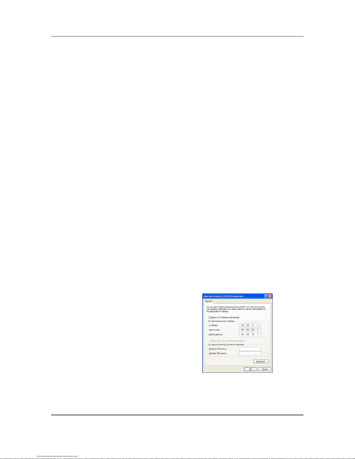
the PC/Notebook to the same network as the 7000 Controller and VSAT Modem.
(If you are using the USB interface, you may skip to step (6).
PC IP addre
ss: A.B.C.D+2
Subnet Mask: 255.255.255.X
Gateway: A.B.C.D
The Gateway is usually the Router IP
address. If no router is used, it is
usually the VSAT Modem IP Address.
iNetVu
®
Flyaway User Manual
Page 32
C-COM Satellite Systems Inc. Page 32 of 38
*Note: The
controller IP should be set in the controller through the LCD
interface prior to entering it into the software tool for proper PC to Controller
Communication through network interface. (USB Interface users may skip
this step)
To Configure the IP address on the controller, you must navigate to the
CONFIG menu using the LCD Interface. (config menu access password =
“password” by default)
a. Navigate to the “IP” menu and press the “ENTER” button.
b. Press the ‘↑’ button to allow for modification on the C_IP field
and set the IP address of the controller.
If router/modem IP is A.B.C.D, controller IP could be
A.B.C.D+1. Press the “ENTER” button once the change is
complete. For example, if the Modem/Router IP is 192.168.0.1
then the controller IP could be set to 192.168.0.2.
c. Press the “Exit” button twice to exit out of the configuration
menu. When prompted if you would like to save configuration,
press the ‘↑’ button to select “Y” (yes), and press “Enter”.
7000 IP: A.B.C.D+1
Subnet Mask: 255.255.255.X (Modem/Router Dependent)
Gateway: A.B.C.D (Router/Modem IP)
d. Click the “reset” button on the controller.
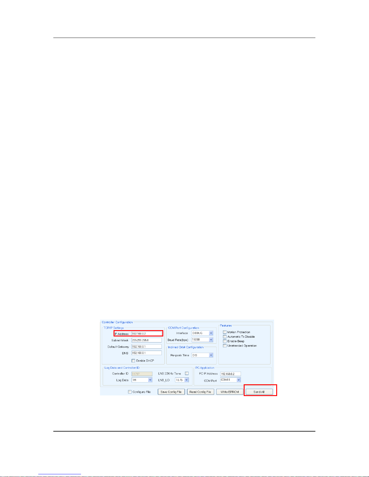
5) Run the iNetVu
®
7000 Mobile Software from the shortcut located on the desktop.
Advance to the “Configuration” screen, by right clicking on the “Controls” screen,
and selecting “Configuration”, and enter the controller IP address in the “TCP/IP
Settings” section as depicted in the figure below. USB users may skip this step.
Click the “Send All” button once the correct IP address is entered.
iNetVu
®
Flyaway User Manual
Page 33
C-COM Satellite Systems Inc. Page 33 of 38
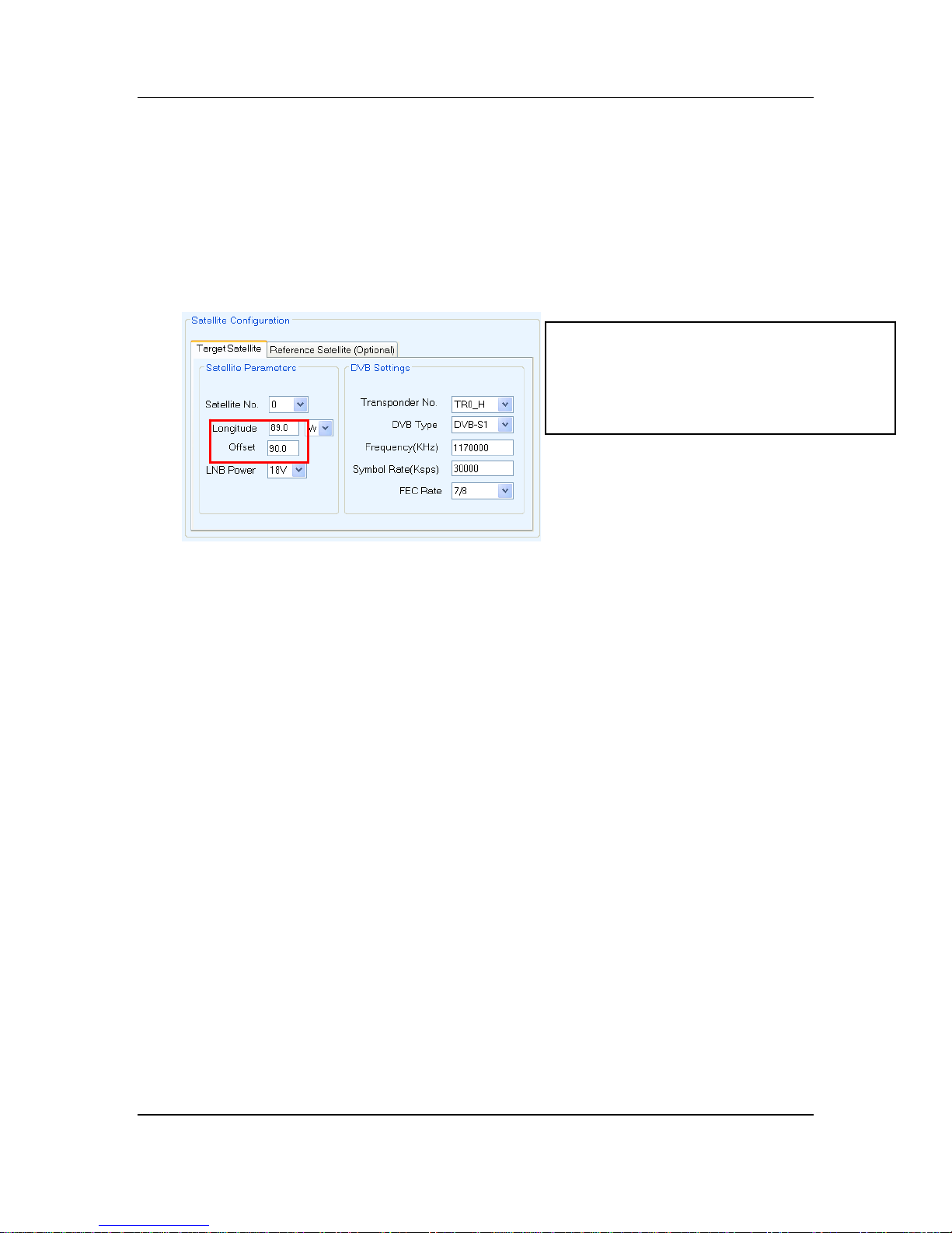
6) While on the “Configuration” screen, Enter the Satellite Longitude and Sat Offset
General Case:
1.2/1.0 Flyaway –Receive Horizontal Offset = 0
--Receive Vertical Offset = 90
The DVB Parameters (TR No., Freq, Sym,
Code Rate), and the LNB_P can be left as is.
The software will automatically set these
parameters after configuration is complete.
More detail will be explained in step 12).
7) Under
the Modem section, set according to your modem specifications:
Type: HNS / iDirect / Viasat / Comtech / Radyne / NA / iPSTAR / Gilat / STM/ Paradise /
Tachyon / (NA-is used for stand alone modem independent satellite
acquisition)
INF (Interface): HTTP (for HNS Only)
TELNET (iDirect / Viasat / Comtech Telnet Interface)
COM (iDirect / Viasat / Comtech / Radyne / STM / Paradise
Console Interface)
SNMP (Radyne Interface)
UDP
NA (Must be selected if NA is the Type)
Rx-Pol (Receive Polarity): H (Horizontal Receive)
V (Vertical Receive)
Tx-Pol (Transmit Polarity): H (Horizontal Transmit)
V (Vertical Transmit)
H (Hemisphere): Hemisphere of Operation (East or West)
*Note: Freq (MHz), Symb (Ksps), IP, and Password fields are NOT required for
Stand Alone Users (Type: NA), and may be left as is.
Freq (MHz): (HNS Users Only) Enter the Modem Frequency
Symb (Ksps): (HNS Users Only) Enter the Modem Symbol Rate
iNetVu
®
Flyaway User Manual
Page 34
C-COM Satellite Systems Inc. Page 34 of 38
DN (Demod No.) (RADYNE MDX Users ONLY) Enter Demodulat
or No.
CN (Carrier No.) (RADYNE MDX Users ONLY) Enter Carrier No.
IP: Enter the Modem IP Address (Default: 192.168.0.1)
Password: Enter the Modem Password. If there is no password,
leave this field blank.
BR_F BR300L users Only (Enter Beacon Frequency)
BR_DB BR300L users Only (Beacon attenuation level: 0dB =
max gain)
22K Enable if 22KHz tone is required for LNB
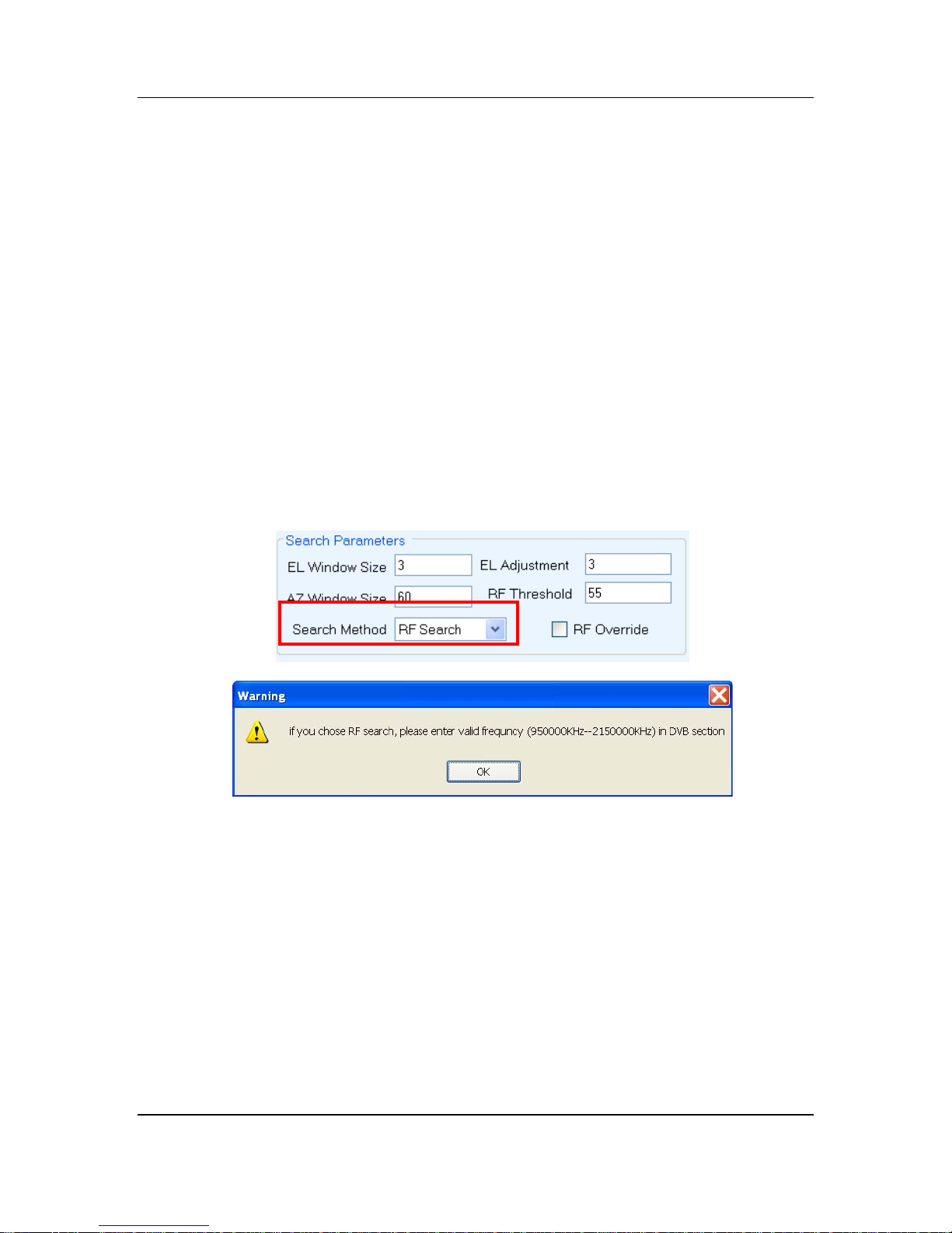
8) If and only if the user chooses to search and peak using RF (not DVB), this option
can be selected in the “Search Parameters” section on the “Maintenance” screen
(valid frequency must be entered in the DVB section of the Configuration screen).
9) Under the “Platform” section ensure the platform type and serial numbers are
correct. (A1200P/A1000P Flyaway)
iNetVu
®
Flyaway User Manual
Page 35
C-COM Satellite Systems Inc. Page 35 of 38
p
10)
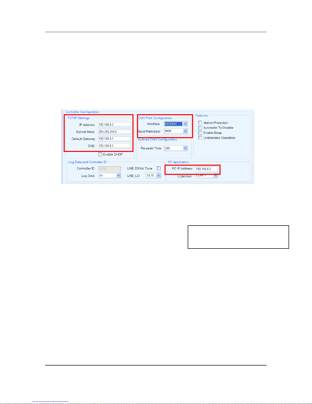
Under the “TCP/IP Settings” section, enter the following:
IP: Controller IP Address
SUB: Controller Subnet Mask
GW: Controller Gateway
DNS: Disregard
RIP: Disregard
Note: PC IP Address must be entered and it must be the same as the controller
y
ou want to connect to.
For iDirect/Viasat/Radyne/Comtech/Gilat/STM/Paradise Users using the Console
Interface:
In the “COM port Configuration” Enter the follow
COM: Modem
ing:
*All other fields could be left as is
unless specifically desired. See
7000 Manual details for other o
SPEED: Depending on the modem baud rate
11) Click “SEND ALL”. This will send all configured parameters to the controller.
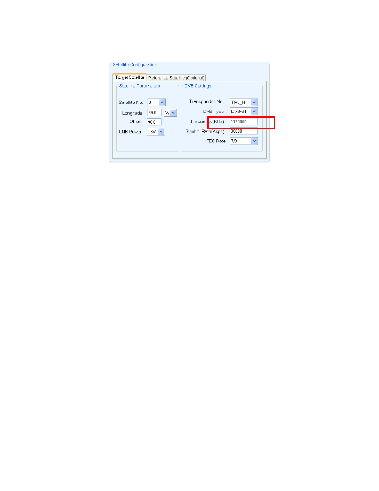
In the Target Satellite Section, the DVB Transponder Frequency, Symbol Rate, FEC Rate
and LNB Power information should automatically set and propagate according to the
Longitude and Transponder selected.
Note: If you choose to modify the DVB Transponder Information, or the LNB Power, you
may do so and click the “Send All” button again.
Remember to click on the “Write EPROM”
button to save the data in the controller.
tions
iNetVu
®
Flyaway User Manual
Page 36
C-COM Satellite Systems Inc. Page 36 of 38
*if you are using a splitter and powering the LNB from the modem, ensure the LNB_P
is DIS. If you are powering the LNB from the controller, enter the proper LNB voltage
requirements.
12) Congratulations you have successfully configured your iNetVu
®
Flyaway System.
Navigate to the “Advanced Controls” menu, if there are any flashing Red, and
Yellow components, stop and troubleshoot. Otherwise, click “Find Satellite”. You
should be online within 2-5 minutes.
13) When complete, you may click on the “Stow Antenna” button, wait until the antenna
is stowed, and power off your 7000 Controller.
*For more detailed information on the iNetVu
iNetVu
®
7000 Controller Manual.
®
7000 Controller interfaces, refer to the
iNetVu
®
Flyaway User Manual
Page 37

C-COM Satellite Systems Inc. Page 37 of 38
6. Appendix
iNetVu
®
Flyaway User Manual
Page 38
C-COM Satellite Systems Inc. Page 38 of 38
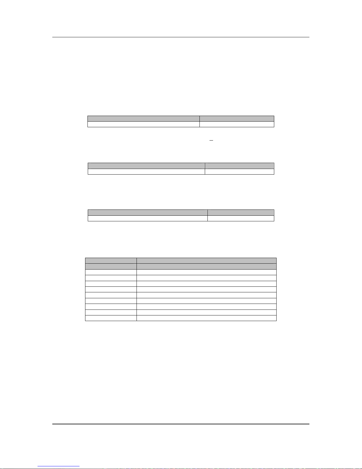
6.1. Appendix 1: Default Limits and Configuration Data Tables
Elevation Offset
1200/1000 Flyaway
EL OFFSET 31.00
Table 2: Default Elevation Offsets. All values are + 2 after Target Calibration.
AZ Potentiometer
1200/1000 Flyaway
AZ ZERO 140.5
Table 3: Azimuth Potentiometer Default Values
PL Potentiometer
1200/1000 Flyaway
PL ZERO 190.7
Table 4: Polarization Potentiometer Default Values
Default Platform Speeds and Limits
PLATFORM TYPES
1200/1000 Flyaway
EL SLOW 6
EL CURRENT6 4.50
EL CURRENT9 6.50
AZ SLOW 5
AZ CURRENT6 4.0
AZ CURRENT9 10.00
PL SLOW 4
PL CURRENT6 1.5
PL CURRENT9 2.0
Table 5 Default values for speed and current limits
iNetVu
®
Flyaway User Manual
 Loading...