

Page 1

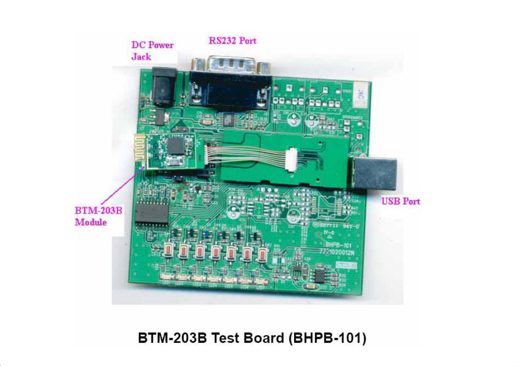
BTM-203B & Test Board
User Guide
Written by Hari Wang
11/10/2006
Page 2
Page 3

Table of Contents
1. Overview...............................................................................................................4
2.System Requirements and Operating System Platforms .......................................4
3. Installing BlueSuite & Widcomm Software ...........................................................4
4.Utilities in BlueSuite .................................................................................................5
4.1 BlueFlash ........................................................................................................5
5 .Technical Support ..................................................................................................19
6 .FCC Information....................................................................................................20
4.1.1 BlueFlash User interface ....................................................................6
4.1.2 BlueFlash Firmware ...........................................................................8
4.2 PSTools ............................................................................................................9
4.2.1 Access Levels .......................................................................................9
4.2.2 PSTools Transport Interface ........................................................... 10
4.2.3 Changing Transport Interface .........................................................11
4.2.4 PSTools User interface .....................................................................13
4.3 BlueChat2 .....................................................................................................14
4.3.1 BlueChat2 User Interface .................................................................15
Page 4

1. Overview
The unit features the following:
z
Test Board containing host I/O and man-machine interface elements including RS232
and USB drivers
headset, plus internal connectors
serial interfaces.
z
Module, which includes the following items:
z
BlueCore chip (an advanced single-chip B lu eto ot h de vi ce ) including Flash
memory
z
device (which stores BlueCore’s firmware and Persistent Store)
RF SMA connector (which allows communication with other Bluetooth dev ice s)
and external connector, audio codec and exter nal audio so cket for a
for PIO lines, audio PCM stream and synchronous
2.
System Requirements and Operating System Platforms
Minimum system requirements for the Casira utilities are:
z
Pentium processor-based personal computer
z
64MB of RAM is recommended
z
10MB of available hard disk space
Utilities can be used on the following operating systems:
z
Microsoft Windows 98 (1)
z
Microsoft Windows Me (1)
z
Microsoft Windows 2000
z
Microsoft Windows NT v4.0 (Service Pack 3 or later)
z
Microsoft Windows XP
AC Adaptor :
Output +5V, DC, 300mA
3. Installing BlueSuite & Widcomm Software
Run the installer supplied on the accompanying CD ROM, pls contact sales.
Page 5

4.Utilities in BlueSuite
z
BlueFlash upgrades the BlueCore firmware.
z
PSTools edits the PS Keys.
z
BlueChat2 creates simple ACL and SCO connectio ns (HCI firmware only).
z
BlueTest exercises the radio for test purposes.
4.1 BlueFlash
BlueFlash is a utility that allows you to download and upload firmware to and from the flash memory on
the Bluetooth modules .From Fig(2), we can insert SPI cable to connector , then link to parallel port of
Host terminals (like Desktop PC , Notebook or Pocket PC)
Page 6

4.1.1 BlueFlash User interface
BlueFlah opens with a user interface windows as Figure 4.1 indicates .
Figure 4.1: BlueFlash User Interface
The function of each button or area is described as follows:
Choose File
(Note:
Download
Verify
Status
Activity Bar
: Opens a dialogue box for selection of the *.xpv file to download to the flash on the
BlueCore Module.
The .xdv file must be present in the same folder as the .xpv file.
hexadecimal-editing w indow. CSR recommends that you do not edit the *.xpv
file in any way. If the code is edited, the Bluetooth protocol stack may behave
erratically and it may no longer be Bluetooth qualif ied.)
: Downloads the selected file to the flash on the BlueCore module. This process will
update each flash block as required and verify them in turn.
:Compares the selected file with the code programmed into the flash on the BlueCore
module. Any differences will be reported in the status area.
: Provides a text report of the status of the current download, upload or verify.
: Displays a visual indication of progress for the current download, upload or
Edit
: Opens a
Start Processor
verification.
: Changes d epending on the status of the processor. If it says
Stop Processor
, the
processo r is running. It should be stopped before attempting to download code.Once
the new code has been loaded, the processor can be restarted by clicking on
Start
Page 7

Firmware ID
Dump
Flash Erase
File ID
File Selection
Flash Type
Processor
.
: Identifies which version of firmware is currently loaded on the module. BlueFlash
does not identify firmware created before Beta 10 release. If BlueFlash is unable to
identify the firmware version, you will still able to upgrade the firmware using this
utility.
: Allows the user to download the contents of the flash to a file on the PC hard drive.
The data can be stored either as BlueCore .xpv/.xdv files or as a binary file. The file
also contains all of the Persistent Store settings, allowing you to restore to a kn o wn
firmware build and Persistent Store settings.
: Provides options for erasing some or all of the flash memory including the Persistent
Store area.
: Displays the name and version of firmware of the file selected for d ownload on the
module.
: This area displays the name and location of the file selected for download.
: This area displays the type of flash memory that has been identified on the BlueCore
module. Flash type is identified when the processor is stopped. Different types of flash
memory may have different memory block structures that require adjustments to
LPT Selection
BlueCore’s memory map. If the flash type indicates
Unrecognised Flash assuming SST
, either the flash on the BlueCore module
is not supp ort ed , o r t her e i s a problem with the SPI connection. See section 5.1.3,
Troubleshooting BlueFlash, for further information.
: This pull-down menu allows the user to select the LPT port to which the SPI cable is
connected.
CSR
: This indicates the version of the BlueFlash application in use.
Page 8

4.1.2 BlueFlash Firmware
There are four possible components in a firmware file:
z
Stack: This is the main runtime code for BlueCore. There are two versions of stack, one
contains all stack layers up to HCI, plus an HCI version of the Virtual Machine (VM); the other
contains sta ck layers up to HCI, plus L2CAP, RFCOMM, SDP and the Virtual Machine (an
RFCOMM version). Both stack versions uses both program and data space.
z
DFU Driver: Device Firmware Upgrade allows for updating the stack, Persistent Store and VM
application over the HCI transport. You cannot use a DFU operation to upgrade the DFU driver.
z
Persistent Store: The Persistent Store holds all the setup and calibration information for
modul e .Mo st set ting s are desi gn - specific, but some are module sp ecific.
BlueFlash firmware is held in *.xpv files (which correspond to the program space) and *.xdv files (which
correspond to the data space). There is a single *.dfu file for DFU. Not all files contain all firmware
components.
Downloading a firmware file only to flash memory overwrites the components contained in the file; all
oth e r s remain intact. This affects only the calibration information in the Persistent Store. Downloading to
flash memory ensures that you can return the module to a known calibrated state if the Persistent Store
becomes corrupted beyond repair.
If firmware with no Persistent Store component is downloaded onto a blank flash, the stack code will
creat e a new Per si ste nt St o re using default values suitable for use on a Casira module. However, some
keys will require calibration per module for optimal performance.
The
Verify
function compares the contents of a firmware file to the contents of flash memory and reports
any d if fe rences (comparing only components contained in the file).
Page 9

4.2 PSTools
PSTools is an editing suite that allows you to read and modify the Persistent Store. The Persistent Store
cons is ts of configuration keys that modify the operation of the firmware. BlueCore is a very flexible device
with many setup options. PS Keys must be set correctly for BlueCore to work in a particular design.
Some PS Keys must be calibrated for each module.
Important Notes
Do not modify Persistent Store values unless you have a clear understanding of what they do. Careless
changes to the Persistent Store could prevent the firmware from executing correctly or can stop module
from communicating with the PC.
:
4.2.1 Access Levels
PSTools has two customer access levels. At the higher access level, there are more PS Keys available
for editing. The customer level s are:
z
User: A minimum number of frequently used keys, e.g., UART baud rate
z
Developer: All the keys that a developer may need to modify
Page 10
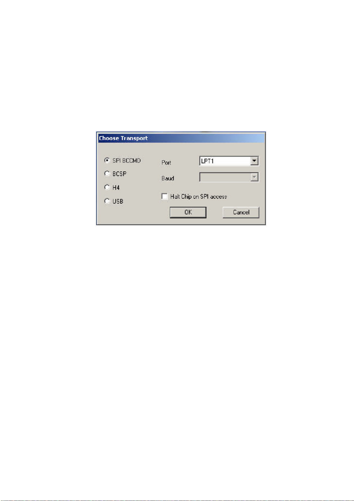
4.2.2 PSTools Transport Interface
PSTools initially opens with a window that allows you to select the interface used to gain access to the
Persistent Store. There are several transport interface options as follows:
SPI BCCMD: W e uses the BlueCore Command (BCCMD ) Protocol running over the SPI transpo rt layer
to edit the Persistent Store. See Figure 4.2.
Important Note:
SPI BCCMD is the recommended method for editing the Persistent Store.
Figu re 4 .2: SPI BCCMD interface
BCSP: We uses the BCCMD Protocol running over BCSP to edit the Persistent Store. BlueCore must be
configured for BCSP via PS Keys. When using this mode, ensure that you are using the correct baud rate
H4: We uses the BCCMD Protocol running over H4 to edit the Persistent Store . BlueCore must be
configured for H4 via PS Keys. When using this mode, ensure that you are using the correct baud rate
settings.
USB: We can use the BCCMD Protocol running over USB to edit the Persistent Store. BlueCore must be
configured for USB via PS Keys.
Page 11

4.2.3 Changing Transport Interface
To change to USB:
1. Change the Host Interface.
z
Select the Host Interface PS Key (505 PSKEY_HOST_INTERFACE).
z
Set to
z
Click on
2. Set D+ Pull-Up
z
Select the USB d+ Pull-up PIO Line PS Key (720 PSKEY_USB_PIO_PULLUP).
z
Set the key to the PIO output that drives the USB D + pull-up resistor. This is PIO[2] on Casira
modules. This key should be set to
is used if the value is
z
Click on
3. Reset BlueCore.
The module is now configured for USB mode.
USB link
Set
Set
using the pull- down menu.
to update the Persistent Store.
0x00
.
to update the Persistent Store.
To change to BCSP:
1. Change the Host Interface.
z
Select the Host Interface PS Key (505 PSKEY_HOST_INTERFACE).
0x02
. If no value is present, then no pull -up is used. PIO[0 ]
z
Set to
Click on
UART link running BCSP
Set
to update the Persistent Store.
using the pull- down menu.
2. Configure the UART interface.
z
Select the PSKEY UART configuration bitfield (517 PSKEY_UART_CONFIG).
z
Set this value to
z
Click on
Set
6
.
to update the Persistent Store.
3. Set baud rate.
z
Select the UART baud rate PS Key (516 PSKEY_UART_BAUD_RATE).
z
Set to the required baud rate (e.g., 115.2 kbaud).
z
Click on
Set
to update the Persistent Store.
4. Reset BlueCore.
This configures the BlueCore module to use BCSP o ver the U AR T.
The UART configuration Bitfiled key is a presentation key. Setting this to
z
UART: Stop Bits PS Key to
z
UART: Parity Bit PS Key to
z
UART: Hardware Flow Control? PS Key to
z
UART: RTS Asserted? PS Key to
z
UART: Enable BCSP-specific hardware PS Key to
One stop bit
Even Parity
Disabled
False
Enabled
z
6
configures the following keys:
Page 12

To change to H4:
1. Change the Host Interface.
z
Select the Host Interface PS Key (505 PSKEY_HOST_INTERFACE).
z
Set to
UART link running H4
using the pull-dow n menu.
z
Click on
Se t
to update the Persistent Store.
2. Configure the UART interface.
z
Select the PSKEY UART configuration bitfield (517 PSKEY_UART_CONFIG).
z
Set this value to
168
.
z
Click on
Set
to update the Persistent Store.
3. Set baud rate.
z
Select the UART baud rate PS Key (516 PSKEY_UART_BAUD_RATE).
z
Set to the required baud rate (e.g., 115.2 kbaud).
z
Click on
Set
to update the Persistent Store.
4. Reset BlueCore.
This configures the BlueCore module to use H4 over the UART.
The UART configuration Bitfiled key is a presentation key. Set th is t o
z
UART: Stop Bits PS Key to
z
UART: Parity Bit PS Key to
z
UART: Hardware Flow Control? PS Key to
z
UART: RTS Asserted? PS Key to
z
UART: Enable BCSP-specific hardware PS Key to
One stop bit
No parity
Enabled
True
False
168
configure to the following keys:
Page 13

4.2.4 PSTools User interface
Once the transport interface has been selected, PSTools opens with a user interface window, as shown
in Figure
5.4. The function of each button or area is described as follows:
Persistent Store Key List
level.
Set
: This button programs the values in the data area into the currently selected PS Key.
Delete
: This button removes a PS Key from the Persistent Store. If required, the stack will create the key
using a default value the next time the stack reboots. Otherwise, the key will continue to be reported in
: This window lists all of the PS Keys that are available at the current access
the status area as
Read
: Clicking this button reads the value of the selected PS Key into the data area. A read is also
“Not present”.
performed every time a new PS Key is selected.
Reconnect
: This button brings up the transport interface selection window, allowing you to reconnect after
resetting or if the transport was disrupted for any reason.
Reset BC
: This button resets the BlueCore device. Any changes to the PS Keys will take effect only after
the device is reset and the stack reboots.
Close
: This shuts down PSTools.
Describe
Status Area
: This button brings up a description of the currently selected PS Key.
: This area provides details such as PS Key number and Friendly Name or Programmer ID
plus the status of the transport interface. If this shows “Entry is not present” for a key that should always
be present (such as the Bluetooth Address) then there are probably problems with the transport nterface.
Data Area
: This area shows the data that is stored in the selected PS Key and allows you to edit it.
Dump
: This button allows you to save PS Keys as you choose. PS Keys can be retrieved through the
Merge
function. See Figure 5.4.
Merge
: This button opens PS Keys that were saved through
Edit Raw
: This item allows you to change the default PS Key setting to one of your own preference (e.g.,
Dump
. See Figure 4.3
baud rate).
Describe
provides more information about each PS Key setting.
Page 14
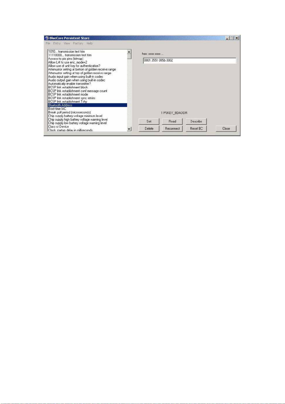
Figure 4.3 : PSTools User Interface
4.3 BlueChat2
BlueChat2 allows users to create an asynchronous connectionless link (ACL) between two devices to
send text or a file and add a synchronous connection orientated (SCO) lin k for a voice connection
between the two devices. Users can select between BCSP, H4 (UART), or USB host interfaces.
BlueChat2 was originally conceived as a demonstration/marketing tool. It is not Bluetooth compliant. It
should be used only for demo nstr ati on and evalua tion purp oses .
The current version of BlueChat2 can only support a point -t o-point connection and will only w ork with HCI
firmware.
Page 15
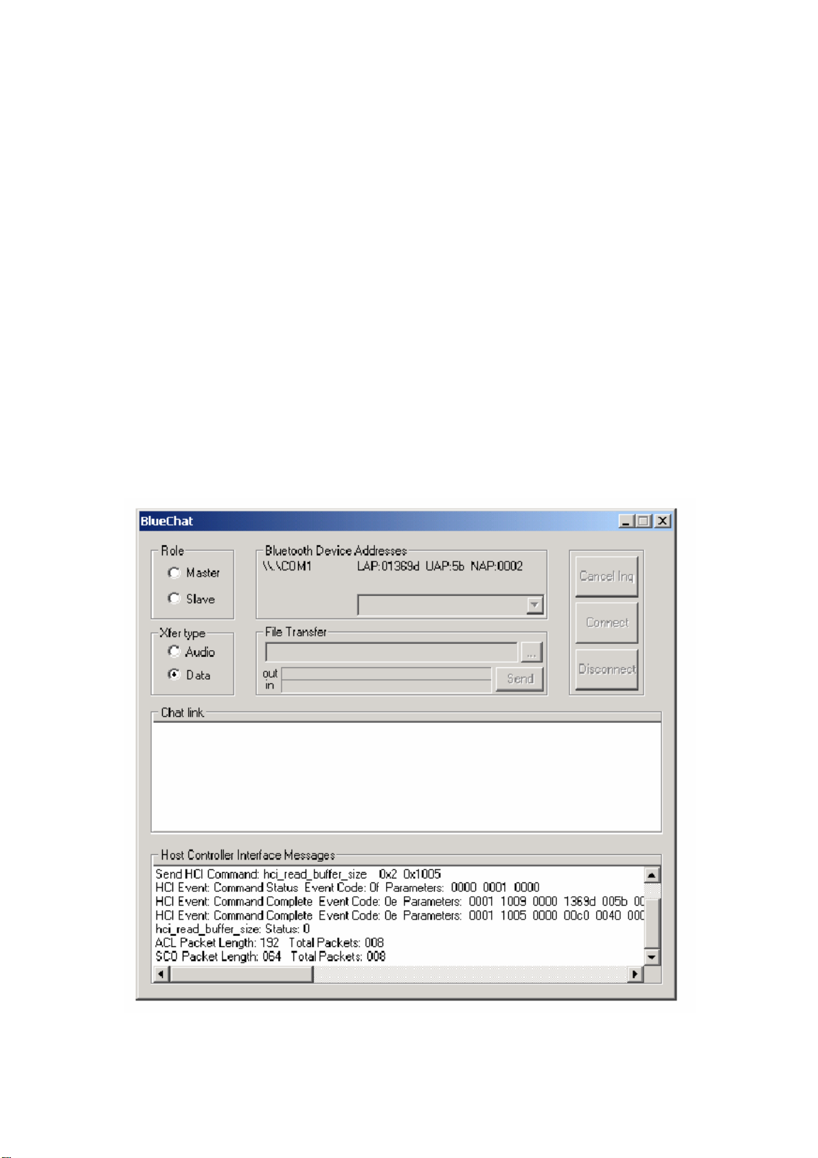
4.3.1 BlueChat2 User Interface
BlueChat2 opens with a user interface window, as Figure 4 . 4 indicates. The function of each button or
area i s described as follows:
Role
: Selects the role for the device as either the master or the slave.
Xfer Type
Chat Link
Host Controller Interfac e Messages
Disconnect
Connect
Audio
Inquiry / Cancel Inquiry
in the area. If the local device is selected to be the slave, this button will be greyed out.
: Selects which type of data is sent.
: Used to send and receive text data.
: HCI commands and responses are displayed here.
: Closes the link between the two devices.
: Establishes a connection to the selected device by setting up an ACL link. If Xfer Type is set to
, a SCO link is also created.
: If the device is the master, this button controls inquiry for other Bluetooth device
Bluetooth Device Address
: This lists the address of the local device and, in the pull-down selection box,
the addresses of any devices found during an inquiry. Use the selection box to highlight the Bluetooth
devi c e to which you wish to connect.
Figu re 4 . 4 : SPI BCCMD interface
Page 16

File Transfer
: Active when connected to another device and Xfer Type “Data” is selected. This displays the
name and the location of the file to be transferred. There are also status bars that show the progress of
files that are being sent or received . Use th e send button to start sending the data to the selected
Bluetooth device.
Examples
To establish an ACL link:
1. Connect both Casira units to a PC (via their host interface).
2. Power up each Casira unit.
3. For each Casira, open a BlueChat2 utility and select the appropriate protocol and baud rates.
The baud rate must b e t he sam e a s t he c ur re nt se tti ng of the PSKEY_UART_BAUD_RATE in
the Persistent Store. Casira modules are supplied set to SP with a baud rate of 115.200kbps.
4. BlueChat2 will find the local device and display its Bluetooth Device Address in the Device On:
field.
5. The HCI window displays the HCI traffic used to configure the device.
6. Select the role of the device. Put one device into Master mode and one into Slav e mode.
7. Selecting the Master will allow the
Inquire
button to be used.
8. Selecting the Slave will put the device into Inquiry Scan mode to allow the Master to connect to
it.
9. On the Master’s BlueChat window, click the
Inquire
button and the Master wi ll perform an inq uiry
to find any slave devices in the area.
10. After the inquiry is finished (which should take about 20 seconds), the Master will show the
addresses of the Bluetooth devices it found during the inquiry. You can cancel the Inquiry at
any time by clicking
Cancel Inquiry
(any devices found before cancellation will display).
11. Select the address of the Bluetooth device you want to connect to in the Bluetooth Address
Box.
12. To connect, click on
Connect
.
13. After connecting, select
Data
in the Xfer type field.
14. You now should have a connection between the two devices. You can send messages
through the chat window or transfer files.
Page 17

To Establish a SCO link:
1. Using PSTools in developer mode, edit the MAP_SCO_OVER_PCM PS Key (427
PSKEY_HOSTIO_MAP_SCO_PCM) and set it to true on both Casiras.
2. Reset Casira.
3. Plug in headsets to Casiras.
4. Follow steps 1 through 8 as for an ACL link above.
5. Select audio in the Xfer field.
6. You now should be able communicate with headsets over an audio SCO link to the other
Casira.
Display
: Two modes of display can be used to view results. Standard and Bit Error. The Bit Error mode
provides a
constantly updated table of the BER results. It will work only with BER tests. The standard mode setting
is the
default and shows a scrolling window containing the individual test results.
Test Results
Test arguments
: This field is where the test results are handled.
: The arguments and parameters for each test can be viewed or set for some tests.
Page 18
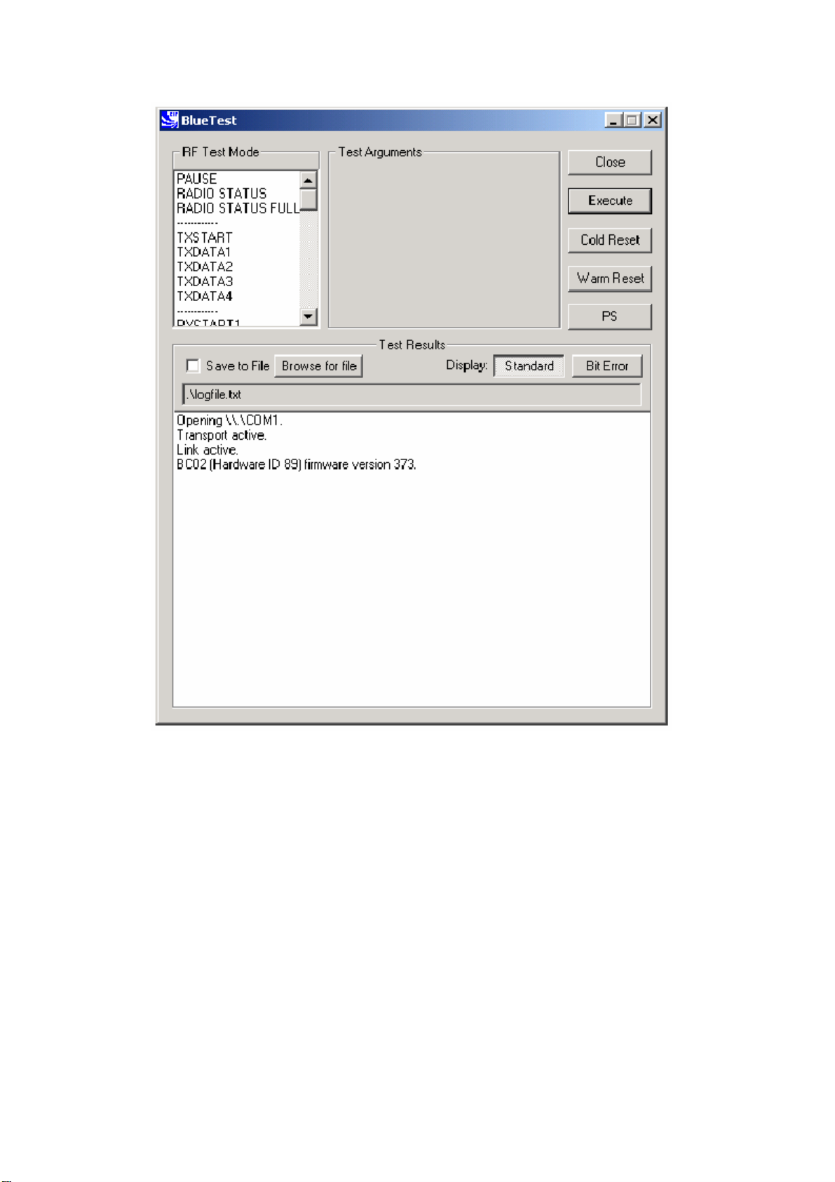
Figure 4.5 : BlueTest User Interface
Page 19

5 .Technical Support
If you encounter difficultie s using unit(s), send a detailed e -mail description of your issue. Provide
as much information as you can to help resolve your problem quickl y .
When contacting technical support, please provide as much useful information as possible. Include the
following details in your e -mail:
Your full name (First and Last)
Company name
Company address
Contact phone number
Description of hardware in use
For technical support, pls send e-mail to : [email protected]
Page 20

6. FCC Information
Federal Communications Commission (FCC) Statement
15.21
You are cautioned that changes or modifications not expressly approved by the part
responsible for compliance could void the user’s authority to operate the equipment.
15.105(b)
This equipment has been tested and found to comply with the limits for a Class B digital
device, pursuant to part 15 of the FCC rules. These limits are designed to provide
reasonable protection against harmful interference in a residential installation. This
equipment generates, uses and can radiate radio frequency energy and, if not installed
and used in accordance with the instructions, may cause harmful interference to radio
communications. However, there is no guarantee that interference will not occur in a
particular installation. If this equipment does cause harmful interference to radio or
television reception, which can be determined by turning the equipment off and on, the
user is encouraged to try to correct the interference by one or more of the following
measures:
-Reorient or relocate the receiving antenna.
-Increase the separation between the equipment and receiver.
-Connect the equipment into an outlet on a circuit different from that to which the
receiver is connected.
-Consult the dealer or an experienced radio/TV technician for help.
Operation is subject to the following two conditions:
1) this device may not cause interference and
2) this device must accept any interference, including interference that may cause
undesired operation of the device.
FCC RF Radiation Exposure Statement:
This equipment complies with FCC radiation exposure limits set forth for an
uncontrolled environment. End users must follow the specific operating instructions for
satisfying RF exposure compliance. This transmitter must not be co-located or operating
in conjunction with any other antenna or transmitter.
Note: The end product shall has the words “Contains Transmitter Module
FCC ID: SMWBTM-203B
 Loading...