

Page 1

Chipley Custom Machine Internals Kit Manual
V 1.0
CCM / DPM
19641 N. Hirsch St
Anderson, Ca 96007
Phone- 530-378-3420
Sales- 1-877-412-6850
Fax- 530-378-3420
www.chipleymachine.com
Page 2

I. Table of Contents:
I. Liability Page 3
II. Safety and Handling Page 4
III. Schematic Page 5
IV. Preparation Page 6
V. Installation Page 12
Page 3

II. Liability:
Chipley Custom Machine and Datum Precision Machining (CCM / DPM) does not
accept any liability for the handling of these markers, tools, air tanks, or any other
item mentioned in this manual. You, the user accept this sole liability when
purchasing and using any paintball marker or paintball accessories. We, CCM /
DPM, disclaim any implied warranties or any responsibility for any errors that
may appear in this manual.
If, as the user of a paintball marker or any of the accessories that CCM / DPM
sells, you do not accept total liability for performing any of the maintenance,
assembly, or work performed in this unofficial manual, CCM / DPM requests that
you do not do anything described in this manual. You are not to use this manual
unless you accept all liability and release CCM / DPM and all of its current and
previous members of all liability through any use or misuse thereof.
Simply by using this manual or using the marker in general you release CCM /
DPM of any and all liability associated with its use. When using a paintball
marker please adhere to all local, state and federal laws.
Page 4

III. Safety and Handling:
A Paintball Marker is not a toy. Any of the tools in this manual are not toys.
Tools and paintball markers should be used only by adults or with adult
supervision. Respect other peoples’ property and when using any paintball
marker, obey all local, state and federal laws. When entering a paintball field,
become aware of their rules and regulations.
It is very important to have the proper paintball protection before going to the
paintball field for play. This includes and is not limited to eye, head, throat, and
body protection. All protection used should be designed for the sport of paintball,
e.g. eye gear designed specifically for paintball usage.
Always have a barrel plug in place and keep the safety ON when handling your
marker. When repairing or cleaning your marker first remove barrel and gas
cylinder, then depressurize your marker by pointing in safe direction and dry
firing. Always treat the paintball marker as if it were loaded.
When handling the marker, always keep your fingers or any other objects away
from the trigger assembly to avoid accidental discharges. Make sure, when
carrying or transporting the marker, to keep the muzzle pointed downward with a
barrel-blocking device in place.
Before transporting your marker through public areas, such as airports, or bus
and trains stations, call ahead for regulatory information regarding the carrying
and transporting of such an item.
Remember, any paintball marker should never be pointed or fired at anyone, and
should only be used at a supervised, licensed and insured paintball field.
Page 5

IV. CCM Economy Pump Kit Schematic:
From left to right – top to bottom:
1. IVG
The CCM® internals set:
2. Main Spring
3. Hammer and Lug
4. Valve Alignment Nut
5. Valve Body and Valve Body O-Ring
6. Valve Pin and Cup Seal
7. Valve Spring.
Page 6

V. Preparation of a Standard Autococker® for the
CCM Internals Kit:
Schematic of a 2004 WGP Prostock® Autococker®. Your ‘cocker might differ – but the parts are
essentially the same.
Step One:
Take off the Grip frame and Beaver Tail from your ‘cocker
Step Two:
Remove Bolt Pin and Slide Bolt from the Body of the marker and the Back Block.
Step Three:
Remove Cocking Rod from the marker.
The back of the marker as it looks after Step One and Two.
Page 7

Step Four:
Unscrew the back block from the marker. You may need to flex the cocking /
pump arm a little - but this is okay. In my the case of the 2004 Prostock® it takes
about 10 full turns to get the back block off the marker.
Your marker will look like this once the Bolt, Bolt Pin, Cocking Rod, and Back Block have been
removed. The brass circle in the bottom tube is the IVG.
Step Five:
Note the depth of the Lug before disassembly. You want to replicate this depth
upon reassembly. It will make timing the marker much easier.
From Left to Right: Valve Alignment Screw, Valve Retaining Nut Set Screw, Hammer (as seen through a cutout in the
body)
Step Six:
Remove the IVG (Internal Velocity Governor) from the marker (3/16th Allen Key
for most Autocockers® – 1/8th for CCM’s). The main spring will also come out at
this point.
Page 8

WGP IVG – Left CCM IVG - Right.
1/8th Allen inserted in a CCM IVG.
Step Seven:
Insert a 1/8
th
Allen key into the Timing Hole (on the top of the marker) and turn
the lug until it is flush with the hammer. This allows for the removal of the
hammer.
Page 9
Cutaway showing the 1/8th Allen Key adjusting the Hammer Lug – shown here flush with the body of the Hammer.
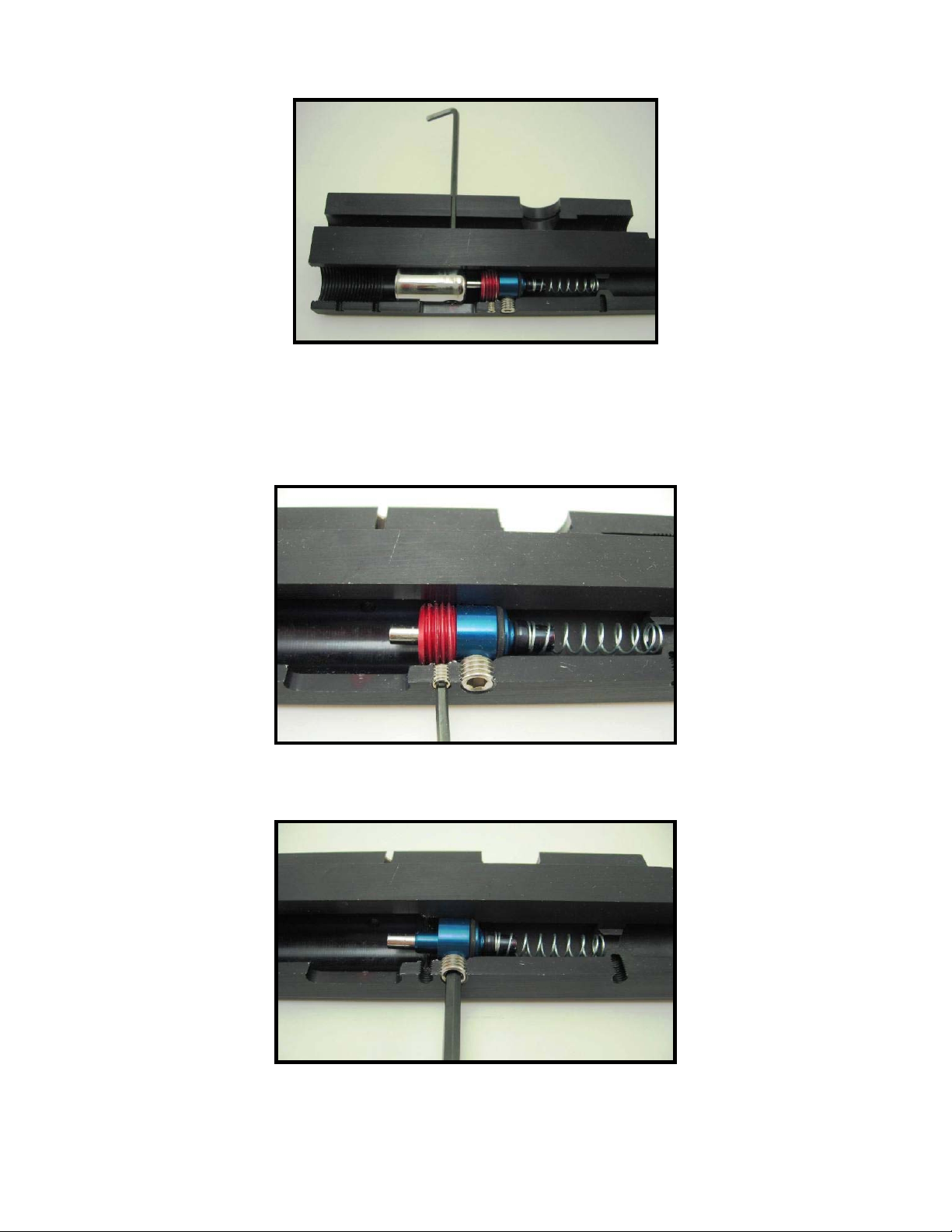
Step Eight:
Remove the Valve Retaining Screw and the Valve Retaining Nut Set Screw from
the bottom of the marker.
Cutaway view showing removal of Valve Retaining Nut Screw.
Cutaway view showing removal Valve Retaining Nut Set Screw.
Page 10

Step Nine:
Insert an Valve Tool into the rear of the bottom tube until you feel it seat deeply
on the Valve Retaining Nut and remove it. CCM® uses a Valve Retaining Nut
Set Screw and the Valve Retaining Nut can be marred. This can make this nut a
bit stiff to remove. Take your time, make sure the tool is seated as deeply as it
can be, and be careful.
An example of a Valve Tool.
Cutaway showing Valve Wrench fully engaged in Valve Retaining Nut.
Page 11

Cutaway showing Valve Wrench removing Valve Retaining Nut.
Step Ten:
Carefully dump out the Valve, Valve Seal, and Valve Spring.
CCM Valve Assembly – Top WGP Valve Assembly Bottom.
Page 12

VI. Installation of the CCM Internals Kit:
Step One:
Stack the Valve Spring, Valve, and Valve body, and Valve Retaining Nut on top
of the Valve Tool (CCM has these available) and slide the body over this
assembly.
Step Two:
Being sure to not cross thread the Valve Retaining Nut begin to screw the Valve
Retaining Nut into the body.
Step Three:
Turn the body of the marker over so that you can see the bottom. Whilst turning
the valve assembly with the Valve Tool line up the bottom of the valve (the small
divot – not the open hole) with the hole left by the removal of the Valve Alignment
Screw. This may take the use of another implement (a ball end Allen key works
well) to make sure that the valve body stays aligned. Only finger tighten the
Valve Retaining Nut at this point.
Page 13

The top of two valves - WGP Valve and Valve Stem – Left CCM Valve and Valve Stem – Right.
Step Four:
Tighten the Valve Retention Screw down on the valve.
Step Five:
Tighten the Valve Retention Nut tight on the Valve. If you attempt to tighten the
Valve Retention Nut before you tighten the Valve Retention Screw – the Valve
tends to spin, causing a misalignment of the valve.
Page 14

Step Six:
If you have a Valve Retaining Nut Set Screw (as the CCM markers do) install this
at this time. Be careful not to over tighten this screw. You want the Retaining
Nut to stay put during use – but you do not want it to become marred.
Step Seven:
Slide the Hammer in the back trying to align the bottom of the Hammer Lug with
the groove cut in the body of the marker.
Two Hammers – CCM Hammer – Left WGP Hammer – Right.
Page 15

Step Eight:
Use a 1/8th Allen Key to Adjust the Hammer Lug. You want the hammer lug to be
approximately at the level of the old hammer.
A CCM Series 5 with Hammer Lug adjusted properly.
Step Nine:
Install the Main Spring and the IVG. Turn the IVG two full turns from flush with
the back of the body.
IVG shown two turns from flush.
Page 16

Step Ten:
Install the Back Block, Cocking Rod, and Bolt into the marker. You are done at
this point.
Cutaway showing the (from left) Cocking Rod, IVG, Main Spring, Hammer (with Hammer Lug), Valve Retention Nut, Valve
Body, ValveStem, Valve Spring
Step Eleven:
If you have an adjustable regulator - back out your regulator adjustment screw
until the marker starts hissing down the barrel when you pull the trigger. Turn it
up until this leak stops. Your marker will most likely be shooting about 230 - 250
FPS. The regulator pressure will be about 300 PSI at this point.
If you are using a stock WGP regulator your reg comes preset at 325 psi and
should be fine from this application. Just skip this step.
Step Twelve:
Shoot your maker (wearing proper safety equipment) over a Chronograph
perhaps three times and not the average of the string.
Step Thirteen:
Turn up your marker by using the regulator until either you achieve 300 FPS in
this manner or the FPS will plateau and after a few more turns starts to decrease
again. This is because you have now given the valve too much pressure and it is
closing faster than it should.
Remember the point where it plateaued and set the regulator at this point.
Step Fourteen:
Use the IVG to set the FPS the rest of the way if your regulator adjustments did
not allow you to reach 300 fps. Turning the IVG in makes the velocity go up –
and turning it out makes the marker go down. From here on out – use only the
IVG to set your velocity.
This is the most efficient setting for your marker and your CCM valve is fully
installed and working well. Congratulations!
 Loading...