

Page 1
WIRELESS SOIL MOISTURE & TEMPERATURE SENSOR
Model: C3102C
User Manual
Thank you for selecting this delicate soil sensor. Utmost care has gone into the design
and manufacture of the sensor. Please read the instructions carefully according to the
version you purchased and keep the manual well for future reference.
OVERVIEW
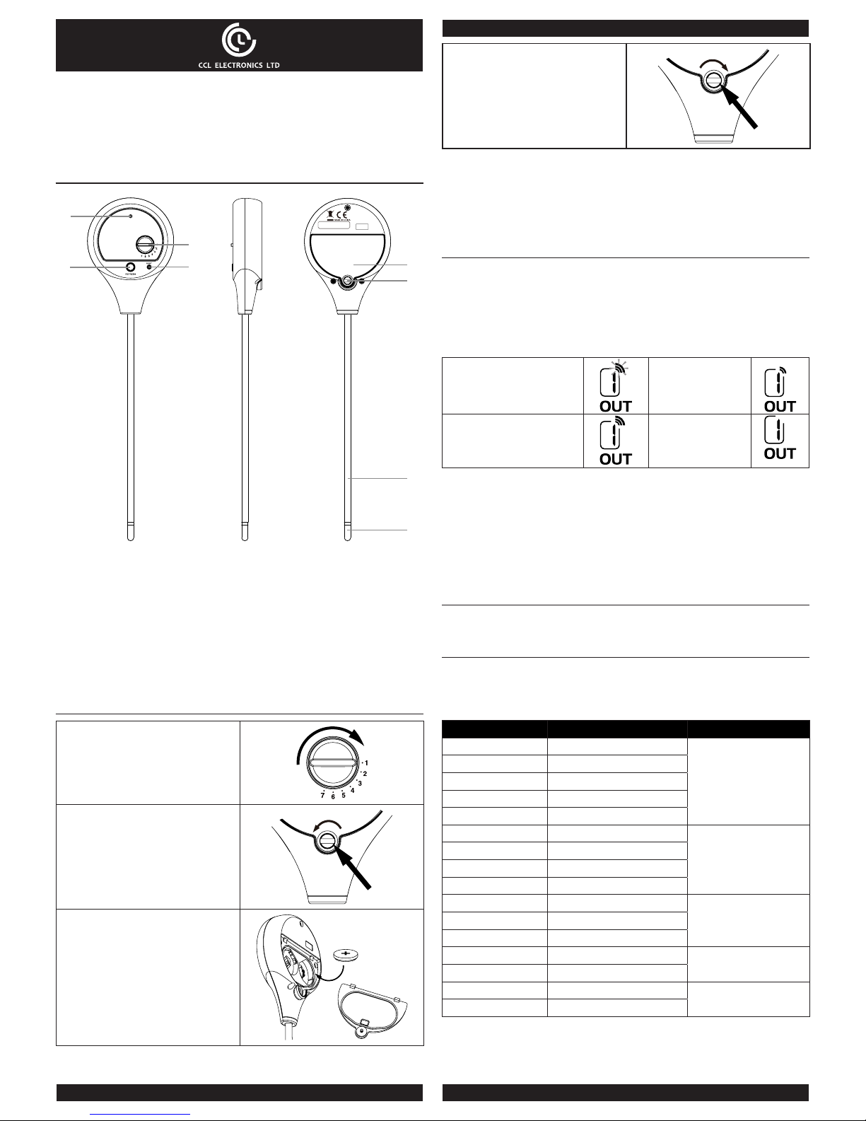
1
2
3
4
5
6
7
8
1. LED indicator
- Blinks once during transmission.
2. [ REFRESH ] key
3. [ CHANNEL ] rotatory selection switch
- Assign the sensor to Channel 1,2,3,4,5,6 or 7.
4. [ RESET ] key
5. Battery compartment
- Accommodates 2 x CR2032 button cells.
6. Battery door screw
7. Sensor metal probes
8. Moisture sensor
GETTING STARTED
1. Select the sensor channel by using
[CHANNEL ] rotatory selection
switch.
For example: Channel 1 is selected.
2. Drive the battery door screw counter
clockwise to open the battery door.
3. Insert 2 x CR2032 button cells into
the battery compartment. Make
sure you insert them the right way
according to the polarity information
marked on the battery compartment.
x
2
4. Cover the battery door and drive the
door screw clockwise to close the
battery door.
Note:
Ensure the water tight O-ring is properly
aligned in place to ensure water resistant.
Note:
- Once the channel is assigned to a Wireless sensor, you can only change it by
removing the batteries or resetting the unit.
- After replacing the batteries of the wireless sensor or the unit fails to receive wireless
sensor signal of a specied channel, press [ SENSOR ] key on the console unit to
manually receive the sensor signal again.
WIRELESS SENSOR SIGNAL RECEIVING (DISPLAY CONSOLE)
This soil sensor can support dierent 7CH console, user can base on the following step
to setup the display console.
1. In normal mode, press the [ SENSOR ] key of the console once to start receiving the
sensor signal of current on displaying channel. The signal icon will ash.
For example, when CH 1 is displayed, pressing [ SENSOR ] key will start receive for
CH 1 only.
2. The signal icon will ash until the reception succeeded. If no signal is received within
5 minutes the icon will disappear.
The icon blinks once every time
when incoming wireless sensor
signal is received (every 60s)
Weak wireless sensor
signal
Fair wireless sensor signal
Bad / no wireless
sensor signal
3. If the signal for Ch 1~7 has discontinued and does not recover within 15 minutes,
the temperature and humidity will display “Er” for the corresponding channel.
4. If the signal does not recover within 48 hours, the “Er” display will become
permanent. You need to replace the batteries of the “Er” channel’s sensors and then
press [ SENSOR ] key to pair up with the sensors per each “Er” channel again.
Note:
The operation or signal icons of dierent display consoles may be dierent, please refer
to the user manual of your display console for more detail.
TEMPERATURE DISPLAY
On the display of the console which the soil sensor is linked to, temperature reading will
be displayed.
SOIL MOISTURE DISPLAY
Soil moisture can be claried into 5 dierent levels: Very Dry, Dry , Moist, Wet and Very
Wet.
To determine the moisture of soil, the sensor calibrate the moisture into 16 points, and
correlate them into percentage value:
Points Percentage Level
1 0%
Very Dry
2 7%
3 13%
4 20%
5 27%
6 33%
Dry
7 40%
8 47%
9 53%
10 60%
Moist11 67%
12 73%
13 80%
Wet
14 87%
15 93%
Very Wet
16 99%
Note:
The measurement accuracy of the sensor can be aected by the soil condition. For
example, the loose soil may get lower moisture level that compare with the dense soil.
Page 2

SENSOR PLACEMENT
Select the suitable installation site that insert the sensor probes into the soil around
100mm (4 inch) and sensor should place within 30 meters of the display console to get
the best transmission performance.
Display
console
Soil sensor
placement
100mm
(4 inch)
30m
(100 feet)
Soil
Note:
Signal transmission range of the sensor will be gradually reduced as sensor is inserted
deeper into the soil. To achieve best transmission range, install the sensor on the same
plain of view as the display console.
REFRESH THE READING ON DISPLAY CONSOLE
The sensor transmits once every 5 minutes automatically to the display console. User
may also press the [ REFRESH ] key on the sensor to manually refresh the readings if
necessary - please note the refresh may take a few seconds up to a minute.
Note:
Some battery operated display consoles may not support this function, please check
your retailer to get more information.
LOW BATTERY ICON
If the sensor is low in battery, the low battery icon “ ” will display on the LCD of the
display console.
Note:
On the display console, the low battery icon will only appear when the corresponding
channel is displaying.
IMPORTANT NOTE
- Read and keep these instructions.
- Do not subject the unit to excessive force, shock, dust, temperature or humidity.
- Do not cover the ventilation holes with any items such as newspapers, curtains etc.
- Do not clean the unit with abrasive or corrosive materials.
- Do not tamper with the unit’s internal components. This invalidates the warranty.
- Only use fresh batteries. Do not mix new and old batteries.
- Do not dispose old batteries as unsorted municipal waste. Collection of such waste
separately for special treatment is necessary.
- Attention! Please dispose of used unit or batteries in an ecologically safe manner.
- Technical specications and user manual contents for this product are subject to
change without notice.
FCC STATEMENT
This device complies with Part 15 of the FCC Rules. Operation is subject to the following
two conditions: (1) this device may not cause harmful interference, and (2) this device
must accept any interference received, including interference that may cause undesired
operation.
Warning: Changes or modications to this unit not expressly approved by the party
responsible for compliance could void the user’s authority to operate the equipment.
NOTE:
This equipment has been tested and found to comply with the limits for a Class B digital
device, pursuant to Part 15 of the FCC Rules. These limits are designed to provide
reasonable protection against harmful interference in a residential installation.
This equipment generates, uses and can radiate radio frequency energy and, if not
installed and used in accordance with the instructions, may cause harmful interference
to radio communications.
However, there is no guarantee that interference will not occur in a particular installation.
If this equipment does cause harmful interference to radio or television reception, which
can be determined by turning the equipment o and on, the user is encouraged to try to
correct the interference by one or more of the following measures:
- Reorient or relocate the receiving antenna.
- Increase the separation between the equipment and receiver.
- Connect the equipment into an outlet on a n a circuit dierent from that to which the
receiver is connected.
- Consult the dealer or an experienced radio/TV technician for help.
SPECIFICATIONS
Dimensions (W x H x D) 65 x 257.5 x 23.5 mm
Main power 2 x CR2032 button cell
Operating temperature range
-40°C ~ 60°C ( -40°F ~ 140°F ) do not recommend
under freeze condition
RF frequency
915 MHz for US version,
868 MHz for EU or UK version,
917 MHz for AU version
RF Transmission interval 5 minute
RF transmission range
(Place on soil ground)
Up to 30m (100 feet) line of sight
 Loading...