

Page 1
Operating & Programming Manual
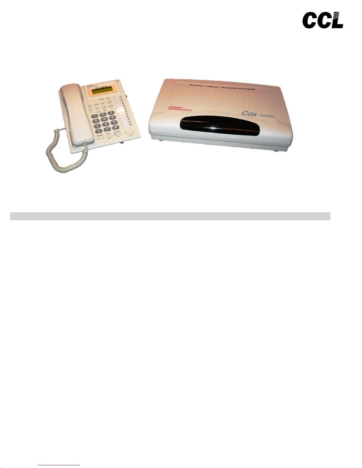
PBX Model: COX- 308 HSK / 832 HSK
We extend a warm welcome to you on becoming a part of the Copper Connections family.
Our service support Engineers shall be working hard through our channel partners to ensure your satisfaction with the
product and after sales services.
We welcome your feedback / query at service@copperconnections.com
. Table of Contents .
Introduction
Installation
KTS & its Keys Description
Terminologies Used
Programming the PBX
Alarm
Allowed Table
Auto Call Back
Auto Call Disconnection
Auto Answer on KTS
Auto Attendant Operations
Auto Attendant Message Modes
Auto Attendant Voice message of 8 Secs
Auto Attendant Voice message of 20 Secs
Auto Attendant - Playing a Company message while the call is ringing on an extension
Auto Attendant Mode settings
Barge-In
Boss Secretary Call
Call Billing / Call Recording & Monitoring / Hotel Management
Call Forward
Call Forward / Do Not Disturb (DND)
Call Pick-Up
Call Parking
Checking Extension Number + Date + Time
CLI (Calling Line Identification)
CLI Transferable / Internal CLI
CLI – Digits addition
CLI Receiving Mode (DTMF / FSK / Auto)
CLI Transmitting Mode (DTMF / FSK)
Computer Connectivity – for Call Logging & Call Voice Recording
Conference / Junction to Junction Call Transfer
Page 2

Date / Time Setting
Day / Night Mode
Denied Table – A
Denied Table – B
Door Phone
Door Lock
DSS Keys Setting
Emergency Call
Extension to Extension call
Extension Call Hold
Flash Time setting
Flexible Numbering
Hold Music
Hot Line
Junction Access During Power Failure
Junction Access Code
Junction Access in Circular / Sequential Mode
Junction Access Control
Junction Dialing Controls
Junction Call Hold + Transfer + Making multiple calls
Junction Dialing Delay Time
Junction - FLASH
Junction Grouping
Junction Ring Assignment
Junction - Enable / Disable
Junction to Junction Forwarding
KTS features
LCR (Least Call Routing)
Memory Dialing
Operator Extension Setting/Operations
Operator / Junction Access code change
Paging
Password
Redial/ Recall from Received or Dialed Out Numbers Data Bank
Remote Programming
Resetting the PBX programming
Ring Time Settings
Ring Tone Change
Walking Class of Service
Terms of Warranty
Notes
- Copper Connections reserves the right to alter equipment specifications and description contained herein and
makes no commitment to update or keep current the information herein. All information herein is subject to
change at any time without notice. No part of this publication shall be deemed to be part of any contract or
commitment whatsoever.
- Product specifications and features are subject to changes without prior notice due to our constant endeavor to
improve the product.
- All features mentioned in this manual are not part of standard systems. Some features need optional
hardware/software up-gradation.
- Not every feature in this manual is likely to have been installed in your system or extension.
Page 3
. Introduction .
Maximum capacity of the PBX:
Model
Junction Lines
Extensions
Door Phones
connectivity
Door Locks
connectivity
832 HSK
8
Numbered as 1
to 8 having
access code as
#11, #12,#13 to
#18
32
- Out of 32 Extensions 4 Ports can be
used as KTS as well as SLT
extensions and 28 are to be used as
SLT only.
- Numbered as 601 to 632
- 602 is the first Operator and 601 the
second.
- Programming can be done from 601,
602, 603 & 604
4
1 Door Phone
consumes 1
Extension port.
2
2nd Lock
connection is
Optional
308 HSK
3
Numbered as 1
to 3 having
access code as
#11, #12 and
#13
8
- Out of 8 Extensions 4 Ports can be
used as KTS as well as SLT
extensions and 4 are to be used as
SLT only.
- Numbered as 601 to 608
- 602 is the first Operator and 601 the
second.
- Programming can be done from 601,
602, 603 & 604
4
1 Door Phone
consumes 1
Extension port.
2
2nd Lock
Operation is
Optional
. Installation .
Cabling
- All cables of the EPABX should be at least 6” away from the electrical cables.
- The KTS Extensions need 4 Core cables. SLT Extensions need 2 Core Cables.
- They should be at least 12” away from the area of high frequencies like tube light
chokes, Electric Motors, etc. If it is not possible to avoid, then use shielded cables
and earth the shield.
Earthing
Earth connected to the EPABX should not have more than 5 volts on it.
3 PIN AC Plug
GOOD EARTHING
BAD EARTHING
Voltmeter reading between N & E
must be more than 100mV and
less than 5V
If voltmeter reading between
N & E is more than 5V, do
not run the Copper
Connections System on it.
Location
- The PBX should be installed in a well ventilated area and at a place where there is no chance of liquid spilling over it or
moisture getting into it (Like in the Bathrooms etc).
- Direct sun light should not fall on the PBX.
- The PBX should be installed on the wall at a minimum of 2 ft height from the floor.
Note: The Company’s warrantee voids if the above points are not followed.
Front Panel Indications
The PBX has a Black Plastic on the front panel.
When PBX is put ON, a RED Led (in the middle of the black plastic) blinks fast indicating that the PBX is configuring itself. After
few seconds, the LED blinks slower indicating that the PBX is now running OK.
There are 8 LED’s corresponding to the 8 Junction lines. They get ON whenever the corresponding Junction Line is assessed by
any Extension.
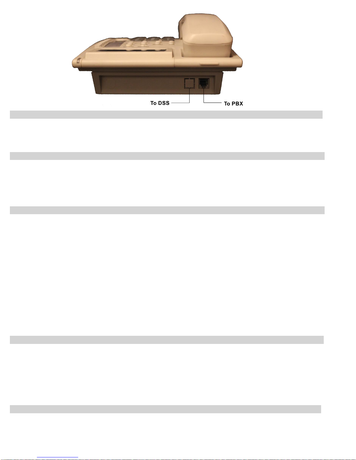
Connections
The PBX has the following connectors on its side panel:
Connectors Description
Broadcast - In default this connector is configured for Door Lock Operation.
/ Door - It can Optionally be used for Paging through an external PA Amplifier or to record conversation of
Extension / Junction. This Option has to be mentioned while placing order with the company.
E.
Page 4

Refer heading “Computer Connectivity – for Call Logging & Call Voice Recording” for further details.
- For Door Lock operation, insert the 3 Pin stereo Plug here. The Shield point of the Plug is the common
point. Whenever, Door Lock operation command is given by any Extension, the “Shield Point” shorts with
the following points of the Jack:
Tip point of the Plug – in case of the 2nd Door Lock
Next to the Tip point of the Plug – in case of the 1st Door Lock
The above shorting acts as a simple switch.
Note: 2nd Door Lock operation is Optional.
Music For connecting External music for Music on Hold.
Insert the 3 Pin stereo Plug of the external Music source, here.
COM - The Battery Lead provided with the system is to be connected here.
Connect 2 SMF rechargeable Batteries (12V 7AH) in series and connect to the Battery Lead. The RED
wire is to be connected to the +ve Terminal of the Battery and Black to the –ve Terminal. The 2
batteries are to be connected in series with the help of a red colored shorting lead provided with the
system. The battery connections are on Pin number 5 & 6. Pin 5 = Gnd and Pin 6 = + 24V DC.
- It can also be connected to a Serial Port of a PC, for operating PC Software for transferring Junction call
details to PC. This is Optional and required PC Software Management. With this option , a special 9 pin to
9 pin lead is provided. That lead would have battery connections as well within it.
With that lead following connections are made:
PBX side connector PC side serial port connector
Pin 2 Pin 3
Pin 3 Pin 2
Pin 5 Pin 5
LINE 1 Terminate the 1st Junction Line here through a RJ Connector.
LINE 2 Terminate the 2nd Junction Line here through a RJ Connector.
LINE 3 Terminate the 3rd Junction Line here through a RJ Connector.
LINE 4 Terminate the 4th Junction Line here through a RJ Connector.
LINE 5 Terminate the 5th Junction Line here through a RJ Connector.
LINE 6 Terminate the 6th Junction Line here through a RJ Connector.
LINE 7 Terminate the 7th Junction Line here through a RJ Connector.
LINE 8 Terminate the 8th Junction Line here through a RJ Connector.
EXT 601 Terminate the 1st Extension wires over here through a RJ Connector.
EXT 602 Terminate the 2nd Extension wires over here through a RJ Connector.
EXT 603 Terminate the 3rd Extension wires over here through a RJ Connector.
EXT 604 Terminate the 4th Extension wires over here through a RJ Connector.
EXT 605 Terminate the 5th Extension wires over here through a RJ Connector.
EXT 606 Terminate the 6th Extension wires over here through a RJ Connector.
EXT 607 Terminate the 7th Extension wires over here through a RJ Connector.
EXT 608 Terminate the 8th Extension wires over here through a RJ Connector.
………………………….
………………………
EXT 632 Terminate the 32nd Extension wires over here through a RJ Connector.
AC 220V Connect the 3 pin main lead here. Make sure that the EARTH wire
connected to it is coming directly from the point where EARTH is created.
On/Off
Switch
on Side
panel of
the PBX It is for switching the PBX ON / OFF. In OFF position the Batteries keep charging.
Note: The PBX is supplied RJ Connectors with short leads for terminating the cables to RJ Sockets. It is recommended to
crimp RJ connectors directly to the cables in order to maintain the aesthetics.
Night Facility
- In default first 4 Junction lines are defined for Night Facility on Extension number 605 to 608. For this setting, all the 8 pins of the DIP
Switch on CPU card should be in ON position.
- In case 8 Junction Lines are used, then Pin no 1,3,5 & 7 of DIP Switch should be in OFF position on the CPU Card.
Precautions:
- The Mains AC socket from where the PBX is given 220 V AC, should be separately made by taking direct connections from
the MCB Box and no other Electrical appliance should be connected on this point.
.
Page 5
KTS & its Keys Description .
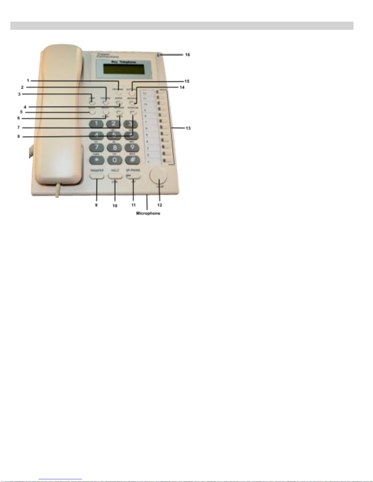
1 PROGRAM : Used for various programming.
2 FWD/ DND : Used for DND (Do Not Disturb) Mode, or Call Forwarding
3 CONF : Used for conferencing.
4 BROAD : Used for External Broadcasting/ Paging + For Group Call + For Monitoring.
5 REDIAL : Used for Redial on Junction Line.
6 RECALL/ FLASH : For retrieving Junction Line while talking to an extension even though the extension has not kept the
handset down
7 AUTO ANS/ MUTE : To activate Auto Answering of incoming calls after one ring
8 INTERCOM (ICM) : For making internal calls or answering them
9 TRANSFER : For transferring junction/ internal calls
10 HOLD/ STORE : For holding a junction/ internal call, and also used while programming
11 SP-PHONE/ EXIT : To activate hands free mode of KTS
12 Navigation Key/ Volume Adjustment key : Up & Down arrows are for volume increase/ decrease, and Left/ Right arrows are
for checking outgoing/ incoming junction call details
13 DSS Key : DSS key numbers 1-8 are for direct access of first 8 junction lines, and 9-12 are for direct access of first four
Extensions. All these DSS keys can be re-programmed for any junction line/ extension.
14 MESSAGE : Not used
15 AUTO DIAL : For Memory Dialing
16 Ringer/ Day-Night Lamp : The flashing condition indicates incoming ring, and continuous ON means system is running in
Night Mode
Only Extension 601-604 can connect with Key Phone.
Page 6
. Terminologies Used .
KTS Lines - KTS Extension lines that can be connected to KTS Instruments.
JUNCTION LINES - Telephone Lines provided by the Department of Telecom.
EXTENSION LINES - Extension Lines mean the EPABX extension lines that can be connected to SLT Telephone Sets.
Note: The first 4 Ports of the PBX numbered 601 to 604 can be connected to SLT as well as KTS Instruments.
. Programming the PBX .
To program most of the feature mentioned in this manual, programming Password is to be entered from any of the first 4 KTS/SLT
extensions (601, 602, 603, 604) through the following command:
#0000 (Here, 0000 is the default Password)
In case of any mistake while programming, dial to reset or else keep the Handset down and pick up again.
Whenever a correct input is entered, PBX will give one single acceptance tone and when wrong input is given, it will give three
tones.
. Alarm .
Alarm calls can be set for extensions from any of the programming extensions (or even from own extension) as described below:
To set Alarm from SLT programming extensions:
Dial #0000 05 NN HH MM #
Where, NN = Last 2 digits of the extension number
HH = 00 – 23 Hours
MM = 00 - 59 Minutes
Dial #0000 05 # (To clear Alarm of all extensions)
Dial #0000 05 NN # (To clear Alarm of “NN” extension)
To set Alarm from your own SLT extension: Dial # 4 HH TT
To set Alarm from KTS:
Lift Handset + # 4
Use Jog Dial to select Extension and to enter the Time
Press “SP-PHONE” key to select any of the parameter.
Press “SP-PHONE” key again to Exit.
Alternately, use the following process:
Press program key once -> Press down arrow nine times -> Press right arrow -> Set the extension ->
Press right/ left arrow -> Set Time -> Press “Hold/ Store” Key -> Press “SP-PHONE” key to Exit
. Allowed Table .
Numbers to be allowed to extensions whose L = 0, are to be defined in this table. For value of L refer “Junction Dialing Controls”.
This table has 16 Locations.
Procedure: Dial #0000 + 43 QQ ABCD#
Where QQ= 01 to 16 (16 Locations of the Table)
ABCD= The starting 9 digits of the Tel numbers to be allowed to extension.
For less than 9 digits, dial # at the end of digits.
To clear this Table: Dial #0000 + 43 #
To clear a particular location of this table: Dial #0000 + 43 QQ #
. Auto Call Back .
From Busy Junction Lines
To get a call back when any of the busy Junction lines get free,
Dial 9
Get engaged tone
Dial #
Page 7

Keep the handset down.
As soon as any one of the busy Junction lines gets free, the Extension will ring. It will ring once and the user can pick
handset within 10 secs to get connected to the Junction line.
From Busy Extensions
To get a call back when any of the busy Extension gets free,
Dial Extension Number
Get engaged tone
Dial #
Keep the handset down.
As soon as the busy Extension gets free, the called and calling Extensions will ring simultaneously.
Note: The above process are true for SLT as well as KTS extensions.
: In case of KTS, Auto Call Back from Junction can also be directly set by dialing #0.
. Auto Call Disconnection .
Selected extensions can be programmed to disconnect Out going Junction call after talking for a set time.
Procedure: Dial #0000
6 NN TT #
Where, NN= Last 2 digits of the Extension Number.
TT= 01 to 99. Time in minutes after which the Junction call is to be disconnected.
Note: In default there is no restriction.
: This auto call disconnection is not applicable on incoming Junction calls.
To cancel this feature, Dial #0000
6 NN 00 #
. Auto Answer on KTS .
KTS instruments can be converted to Auto Answer mode by pressing the “AUTOANS” key.
In this mode, all internal calls coming to it, will get answered in hands free mode, automatically. When the conversation is over it
will disconnect itself automatically.
. Auto Attendant Operations .
When the PBX is operated in this mode, the Junction caller gets a welcome message.
Thereafter there could be different situations explained below:
- If the Caller dials an extension (other than the Operator) and the extension is busy, the call will ring on the Operator.
At this moment the extension gets an Alert tone.
However, the engaged extension can still pick the call through the following process:
Hold the previous call by FLASH
Dial # 9
FLASH to Hold this call or keep Handset down to disconnect this call
Dial # 9 to retrieve the previous call.
- If the caller dials 0 for Operator & the operator is busy, following would be the options:
The call will ring on the 2nd Operator, if it is made in the PBX. If not then the Operator will get an alert tone. The
Operator can then attend the 2nd call as per the following procedure:
Press HOLD key
Dial # 9
Talk to the 2nd call
Keep the Handset back to disconnect the 2nd call or press HOLD to hold
the 2nd call as well.
Press the DSS key of the 1st call and talk.
Similarly, more than 2 calls can be attended.
Note: If 2 Operators are made and both of them are busy then the incoming call will alert the 1st Operator with a
tone. The 1st operator can then attend to it with the same process as explained above.
. Auto Attendant Message Modes .
In Auto Attendant Mode, voice messages can be recorded in either of the following two Modes:
8Secs Welcome Message + 6 Secs Busy Message + 6 Secs No Answer message
Or
20 Secs Welcome Message / Company Message
These two procedures are explained below under separate headings.
. Auto Attendant Voice message of 8 Secs .
Three types of messages can be recorded for the following 3 conditions:
Welcome Message (8 Secs)
Busy Message (6 Secs)
No Answer Message (6 Secs)
Procedure to record message (SLT/ KTS):
Page 8

Dial #0000 + 12 M # - now record the message through the Handset.
Here, M = 1 for Welcome Message
2 for Busy Message
3 for No Answer Message
To listen to the recorded message (SLT/ KTS):
Dial #0000 + 13 M # - listen to the message
Options for the case when caller doesn’t dial any number or dials a Wrong Number
When the caller doesn’t dial any number for 5 secs after the DISA message, one of the following 3 options can be set in the
system:
Release the Junction Line
Dial #0000 + 160 #
Transfer the call to Operator
Dial #0000 + 161 #
Transfer the call as defined in Junction Landing in Day/Night Mode
Dial #0000 + 1616 #
Default: The PBX transfers the call to Operator.
Note: When 12M programming is done, the PBX starts working in 8 Secs message mode.
. Auto Attendant Voice message of 20 Secs .
Welcome Message can be made 20 Secs in place of 8 Secs. In this case “Extension Busy Condition” and “Extension No Answer
Condition” are replied by the system in any of the following ways.
Procedure to record messages (SLT/KTS):
To record 20 Secs Welcome Message,
Dial #0000 + 1200 # - now record the Welcome message for 20 secs through the Handset.
To Listen to the 20 Secs Welcome Message (SLT/KTS):,
Dial #0000 + 1300 #
Options for the case when caller doesn’t dial any number or dials a Wrong Number
When the caller doesn’t dial any number for 5 secs after the DISA message, one of the following 3 options can be set in the
system:
Release the Junction Line
Dial #0000 + 160 #
Transfer the call to Operator
Dial #0000 + 161 #
Transfer the call as defined in Junction Landing in Day/Night Mode
Dial #0000 + 1616 #
Default: The PBX transfers the call to Operator.
Note: When 1200 # programming is done, the PBX starts working in 20 Secs message mode.
. Auto Attendant - Playing a Company message while the call is ringing on an extension .
Paradoxically, this option works in “Direct Ring Mode” and not “Auto Attendant Mode”.
This feature is for promoting a company’s message by playing Company Message in place of the Ring Back Tone while the
incoming Junction call is ringing on defined Extension/Operator.
Keep the Junction in Auto Attendant Mode.
Record Auto Attendant message in 20 Seconds message mode.
Dial #0000 + 1670 # (Junction calls will ring on the Consoles while the caller will hear recorded message in place of
the Ring Back Tone)
Dial #0000 + 1676 # (Junction calls will ring on the Extensions that are defined in Direct Ring Mode while the caller
will hear recorded message in place of the Ring Back Tone)
Dial #0000 + 167 # (Feature disabled)
Note: The above programming is true for SLT as well as KTS. However, KTS has an option to do the above through another
process given under the heading ‘KTS Features’ by the name ‘CRBT’.
. Auto Attendant Mode settings .
To set one or all the Junction lines in Auto Attendant mode:
Dial #0000 + 10 # (To set all the Junction lines in Auto Attendant Mode)
Dial #0000 + 10 J # (To set Junction line number J in Auto Attendant Mode)
Where, J = 1,2 or 3 representing 1st, 2nd or 3rd Junction Line.
To shift all Junction Lines from Auto Attendant mode to Normal mode, Dial #0000 + 11 #
Note: In default all the Junction lines are in Direct Ring Mode
: When a junction is set in “Auto Attendant Mode”, “Direct Ring Mode” automatically gets cancelled.
Simultaneous 2 Junction calls in Auto Attendant Mode
The PBX can attend a Junction call at a time. To attend to 2 Junction calls simultaneously an Optional card is to be added to the
PBX.
Following are the options to attend to the Junction calls coming in while the PBX is busy attending a Junction call in Auto Attendant
mode:
Page 9

Dial #0000 + 1540 # (The 2nd and subsequent caller will not hear anything until the Welcome Message of the 1st call is
over.
Dial #0000 + 1541 # (The 2nd and subsequent callers will ring on Operator or extensions that are defined in Direct
Ring mode.)
Note: The above programming is true for SLT as well as KTS. However, KTS has an option to do the above through another
process given under the heading ‘KTS Features’.
. Barge-In .
Extension number 601 and 602 has the facility to barge into any Extension of Junction Line and over hear or talk in conference.
However, extensions 603 and 604 (if they are KTS instruments) can also Barge into an extension.
From SLT/KTS
Dial # 71 J - To listen to a Junction line (only from 601 and 602)
(J = 1 to 8, the Junction to be barged into)
Dial # 72 XXX - To listen to an Extension,
Where, XXX= Ext Number 603 to 632
From KTS
Besides the above codes, following is additionally possible from KTS:
Pick Up Handset
Press BROAD Key + 3 + Extension Number (For Barging Junction follow the SLT/KTS code)
Disabling Barge-In to particular KTS:
Particular KTS phone can be programmed whereby it cannot be barged in.
Process:
Press ‘Program Key’ twice + Press Left/ Right arrow to enter + Press Up/ Down arrow to select KP Monitor +
Press Left/ Right arrow to Enable/ Disable + Press ‘Store/ Hold’ Key
. Boss Secretary Call .
A BOSS can divert all incoming calls to his Secretary by dialing # 81 XXX from its own extension. Where XXX is the extension
number of the Secretary.
To cancel the feature, Dial # 81 # from the BOSS Extension.
Note: When any extension calls BOSS, the call will go the Secretary.
Secretary extension can hold the call with FLASH and transfer to the BOSS Extension. It is true for internal as well
as Junction calls. Secretary can call the BOSS directly.
. Call Billing / Call Recording & Monitoring / Hotel Management .
The PBX stores approximately 3,000 last Junction calls (dialed out) record in its memory. The output of these records can be
taken on a computer by connecting Serial Port of the PBX to the serial port of PC. Optional PC Management Software has to be
installed in PC, for this purpose.
With PC connectivity, the PBX sends Incoming as well as outgoing call details to the software & software stores the same in PC.
Also the PBX stores upto appox. 3,000 outgoing calls (not incoming) in its memory.
The PC software shows the Incoming calls only if the software is open. If the software is not open then incoming calls get lost.
However, outgoing calls are not lost because whenever software is opened, the PBX sends the missed outgoing calls to the
software.
User can take excel files or print of the calls details with various filters from the software.
Note: If the software is operated without activation key then programming through software, Pass word changeability & other
Management operations cannot be done.
Setting of sensing call maturity
PBX would consider a Junction call as matured in either of the following two ways:
On getting reversal from the Junction Line
or
On Time delay based calculations.
Dial #0000 + 0300 # - To set billing on getting reversal
Dial #0000 + 03TT # - To set billing on Time delay mode.
Where, TT = 01 – 99 secs. The billing will start after TT secs of
accessing the Junction line.
Default setting = Billing starts after 5 secs of accessing Junction.
PC Management software
This software provides following features:
Call details
Calls recording / Monitoring
Recording, playing and downloading of Auto Attendant Messages
Hotel Management
Call details
Call charges can be defined in it and Various reports can be taken.
The details include following:
Extension Number
Page 10

Called number
Junction Number
Date/Time of call
Duration of call
Cost of call
Etc
Calls recording / Monitoring
Conversation of calls made from defined Extensions or on defined Junctions can be recorded in the PC. If many extensions or
Junctions are marked for recording then it will record one conversation at a time. If more than one conversation is on then it will
record the first initiated call.
User can also over hear any conversation through this software from the PC.
Recording, playing and downloading of Auto Attendant Messages
Auto Attendant Messages can be recorded and played through this software or can be down loaded to PBX.
For this operation, Broadcast/Door connector on the PBX has to be used in “Broadcast” mode and is Optional. If this is used then
Door Lock operation cannot be used.
Hotel Management
Feature like Call billing, Check In/out, cash deposit, add deposit, etc are available when operated through this mode of the
software.
To operate Hotel Management, set the PBX in Hotel Management mode as below:
Dial #0000 + 8851 – Te set the PBX in Hotel Management mode.
Dial #0000 + 8850 – Te set the PBX in normal mode. This is the default setting.
. Call Forward .
There are two types of Call Forwarding:
Call Forward Always
An extension can divert all incoming calls to another extension by dialing # 81 XXX from its own extension. Where XXX is the
extension number where calls are to be diverted.
To clear this Call Forward Always feature, Dial # 81 #
This feature can also be programmed from any of the Programming Extensions as explained below:
Dial # 26 NN XXX
Where, XXX= Extension number where Calls are to be forwarded.
NN= The last 2 digits of the original Extension.
Dial # 26 NN # (To clear the feature of NN Extension from any of the programming Extension)
Dial # 26 # (To clear the Call Forward Always feature of all the extensions. To be dialed from any of the
programming Extension)
Call Forward When Busy / No Answer (This can also be used as Round Robin feature)
If calls are to be diverted only when the Extension is busy or is not answering, then,
Dial # 82 XXX from its own extension. XXX= Extension where calls are to be Diverted.
To clear this Call Forward, Dial #82#
This feature can also be programmed from any of the Programming Extensions as explained below:
Dial # 27 NN XXX
Where, XXX= Extension number where Calls are to be forwarded.
NN= The last 2 digits of the original Extension.
Dial # 27 NN # (To clear the feature of NN Extension from any of the programming Extension:
Note: To cancel all type of Call Forwarding, DND, Auto Call Back, Alarm clock of own Extension:
Dial # 80 from its own extension
: To cancel Call Forwarding Busy / No Answer of all the extensions,
Dial # 27 # from any of the programming Extensions.
: To cancel all type of Call Forwarding of all the extensions,
Dial # 25 # from any of the programming Extensions.
: To retain the Call Forwarding programming after the PBX is switched ON/OFF,
Dial #0000 + 171 # (This is the default setting in the PBX)
: To lose the Call Forwarding programming after the PBX is switched ON/OFF,
Dial #0000 + 170 #
Ring Time change in Call Forward When Busy / No Answer
The ring time on extension, in case of Call Forward, can be changed using the following program:
Dial #0000 + 184 TT #
Where, TT= 01 – 99 Ring Time in seconds
Default value = 20 secs / 10 secs in some models.
Note: The time entered here, should be less than the Internal Call Ringing Time.
: Call Forward can also be done through the commands given in “Call Forward / Do Not Disturb (DND)”
. Call Forward / Do Not Disturb (DND) .
Do Not Disturb (DND)
Page 11

In DND mode, no one can call the DND extension.
PROCEDURE: From SLT Dial # 83
From KTS Dial # 83
Or
Press “FWD/DND” Key + 3
To cancel DND on SLT, simply lift Handset.
To cancel DND on KTS, Press “FWD/DND” key + “0”
Call Forward
Lift Handset - Press “FWD/DND” + 1 + Extension Number (where calls are to be Forwarded in all conditions)
OR
Lift Handset - Press “FWD/DND” + 2 + Extension Number (where calls are to be Forwarded when the KTS is busy)
To cancel DND on KTS, Dial press “FWD/DND” key + Dial “0”
Note: When the KTS Extension is set in Call Forward mode, the “FWD/DND” LED blinks RED.
: When the KTS Extension is set in “DND” mode, its “FWD/DND” LED glows RED.
. Call Pick-Up .
PBX has various codes for call pick up as detailed below:
Dial # 9 - To pick up calls in the following sequence:
Junction Call being transferred
Incoming Junction Call ringing
Parked Call
Junction Call on Hold
Door Phone Call
Internal Call
Dial # 3 XXX - To pick the call ringing on a particular Extension.
Where, XXX = Extension Number
Dial # 1 J - To pick a particular Junction call (either ringing or on HOLD).
Where, J = Junction Number
Dial # # - To pick the parked call. The 1st parked call gets picked first. This same code is also used for parking a
Junction call.
. Call Parking .
One or more Junction calls can be parked from any extension.
Procedure:
Dial FLASH + # # - While talking on a Junction line, to park the call.
One or more Junction calls can be parked from any extension by dialing FLASH + ##
Dial # # - from the same extension or from any other extension, to retrieve the first parked call.
Dial # 9 from the same extension or from any other extension, to pick up calls in the following sequence:
Junction Call being transferred
Incoming Junction Call ringing
Parked Call
Junction Call on Hold
Door Phone Call
Internal Call
Call Parking Hold time can be changed through the following program:
Dial #0000 + 186 TT #
Where, TT= 01 to 99. (01 means 10 Secs and 99 means 990 secs)
In default the value is 12 i.e., 120 secs.
Note: In case of KTS there is no need to park a call because it can simply HOLD the call and retrieve by directly pressing
the DSS key of the Junction.
. Checking Extension Number + Date + Time .
To know the extension number of an extension or PBX date or PBX time, do the following:
From SLT extension having CLI Telephone Set
Dial # 62 and keep the handset down.
The extension will ring and its number shall be displayed on the CLI phone. The display may show a 5 digit
number. In that case the last 3 digits would be the Extension number.
Dial # 63 – To see the PBX time
Dial # 66 – To see the PBX date
Dial # 64 – To see the PBX version
From SLT extension having Telephone Set w/o CLI
Dial # 60 – to know the last 2 digits
Hear tones denoting 2 digits of Extension number.
Example: If the extension number is 601, you will hear 10 Tones and then 1 Tone with a gap of 1.5 secs. 10
Tones indicate digit number 0 and 1 Tone indicates digit 1.
Page 12

Dial # 61– to know the last 3 digits
Hear tones denoting 3 digits of Extension number.
Example: If the extension number is 601, you will hear 6 Tones, 10 Tones and then 1 Tone with a gap of 1.5
secs. 6 Tones indicate digit 6. 10 Tones indicate digit number 0 and 1 Tone indicates digit 1.
From KTS Extension
Lift Handset + 6 + Press Up/ Down arrows of Navigation Key
. CLI (Calling Line Identification) .
The incoming Junction call telephone number is displayed on the LCD of the CLI phone on which the defined Junction call rings.
This feature will work with Telephones having CLI feature.
. CLI Transferable / Internal CLI .
When a Junction call is transferred from an extension to another extension, the external telephone number is displayed on the LCD
of the CLI phone. When an extension calls another extension, Extension number is displayed on the LCD of the CLI phone.
. CLI – Digits addition .
Some CLI Telephones cannot display less than 4 digit numbers. In that case if the PBX extension numbers are less than 4 digits
then additional dummy numbers need to be added by the PBX.
Procedure: Dial #0000 + 180 KK #
Where KK = Any 2 digit
To Disable dial #0000 + 180 #
Note: The above programming is true for SLT as well as KTS. However, KTS has an option to do the above through another
process given under the heading ‘KTS Features’.
. CLI Receiving Mode (DTMF / FSK / Auto) .
The system senses CLI on Junction lines in DTMF mode or FSK mode or it can be programmed in auto mode to detect either of the
two.
Procedure: Dial #0000 + 1812 # - for FSK mode
Dial #0000 + 1813 # - for DTMF mode
Dial #0000 + 1814 # - for Auto Detection mode
Dial #0000 + 1815 # - for always FSK & DTMF mode
Default: Auto Detection mode.
Note: The above programming is true for SLT as well as KTS. However, KTS has an option to do the above through another
process given under the heading ‘KTS Features’.
. CLI Transmitting Mode (DTMF / FSK) .
The PBX generates CLI on Extensions in FSK mode in default.
For other modes, Dial #0000 + 1811 # - for DTMF mode
Dial #0000 + 1810 # for FSK mode
Note: The above programming is true for SLT as well as KTS. However, KTS has an option to do the above through another
process given under the heading ‘KTS Features’.
. Computer Connectivity – for Call Logging & Call Voice Recording .
following features can be availed when PBX is connected to a Computer & a software is loaded:
PBX Programming (Most of the Programming that can be done from Extension, can also be done through this
software).
Hotel management (Features like Check-In / Check-Out, etc)
Call Details recording
Call Conversation recording (If the PBX is with Door Lock operation then this feature cannot be used.)
The PBX can be connected to a PC by installing optional “PC Interface Card”. PBX is connected to the PC through a “RJ to RS232 Lead” (explained
under the heading “Installation”).
A software is loaded in the PC which can work in the back ground while it is being used for other applications.
The PC then records all the call details and the user can see them with various filter options.
The PBX also has memory to store call details of up to 3,000 calls. This helps in storing the data when the PC is down or not connected.
As soon as the PC is connected, the stored call details get transferred from the PBX to PC & are deleted from the PBX memory.
For recording of Call Voice, connect the ”Broadcast” socket of the PBX to MIC point of the PC (Refer heading “Installation”).
Refer “PC Interface Software” Manual for assigning Extensions / Junctions for conversation recording.
Any number of Junction or Extensions can be programmed for recording. However, PBX will record one call at a time. In case there are more than
1 conversation going on, the PBX will record the first initiated call.
Note: All programing of the PBX can be done from the PC as well as SLT. However, programming through PC is more convenient.
. Conference / Junction to Junction Call Transfer .
The PBX supports three type of Conferencing:
Between 2 Extension & 1 Junction
Between 1 Extension & 2 Junction
Between 2 Junction
Page 13

Between 2 Extension & 1 Junction
Following is the procedure to established conference between 2 Extensions and a Junction line:
From SLT Extension
During conversation with a Junction line, Hook-Flash to hold the line.
Then dial XXX Where, XXX = Extension Number.
From KTS Extension
During conversation with a Junction line, press “CONF” Key
Dial Extension Number
Press “CONF” Key
Conference will start
Between 1 Extension & 2 Junction
From SLT Extension
During conversation with a Junction line
FLASH
Dial ##
Pick up another Junction by dialing 9 & dial required Tel number
FLASH
Dial #
Conference will start.
To end the conference, extension has to keep handset down.
From KTS Extension
During conversation with a Junction line
Press CONF Key
Press DSS key of a free Junction
Dial required Tel number
Press CONF Key
Conference will start.
When KTS keeps Handset down, the conference will end.
Between 2 Junction
From SLT Extension
During conversation with a Junction line
FLASH
Dial ##
Pick up another Junction by dialing 9 & dial required Tel number
FLASH
Dial # 6
Conference will start.
Extension can keep the Handset down but cannot use its extension for any other purpose until the conference is
over.
Extension will ring once every 20 secs to remind about the conference
Whenever the Extension picks up, it will join the conference but on keeping the handset down this time, the
conference will end.
From KTS Extension
During conversation with a Junction line
Press CONF Key
Press DSS key of a free Junction
Dial required Tel number
Press CONF Key
Conference will start.
Press CONF Key again
Keep the Handset down
Conference will continue between the 2 Junction lines
KTS will ring once every 20 secs to remind about the conference
KTS can over hear the conference anytime by simply lifting the handset
To allow the conference to continue, KTS should press CONF key and keep handset down
To end the conference keep Handset down without pressing CONF key
Page 14

. Date / Time Setting .
To set the date and time of the PBX, follow the following:
Dial #0000 + 01 YY MM DD #
Where, YY= Year (12 for 2012)
MM = Month (01 – 12)
DD = Date (01 – 31)
Dial #0000 + 02 HH TT #
Where, HH= Hour (00 for 23)
TT = Minutes (00 – 59)
Dial #0000 + 02 0000 W #
Where, W = Week (1 to 7. 1 for Monday & 7 for Sunday)
Settings from KTS:
Press ‘Program’ Key once + Press Down/ Up arrow to Select ‘Date & Time’ + Press Left/ Right arrow to set the time
. Day / Night Mode .
The PBX can be configured in 2 sets of programming. One for the day mode and one for the night mode.
The PBX can shift to Day or Night mode in following 2 modes:
Manual Change Mode
Auto Change Mode
In default the PBX is in Manual Day Mode.
Manual Change Mode
Dial #0000 + 041 # - To operate in Manual Change Mode
Procedure from SLT/KTS:
Dial #20# - to change the system to Day Mode
Dial #21# - to change the system to Night Mode
Auto Change Mode
Dial #0000 + 040 # - To operate in Auto Change Mode
Dial #0000 + 042 HH MM #
Where, HH = 00-23 Day Mode start Hours
MM = 00-59 minutes
Dial #0000 + 043 HH MM #
Where, HH = 00-23 Day Mode end Hours
MM = 00-59 minutes
Dial #0000 + 0440 # - To enable “Auto Attendant Mode” in Day and Night mode.
Dial #0000 + 0441 # - To enable “Auto Attendant Mode” in Day and “Direct Ring Mode” in Night mode.
Dial #0000 + 0442 # - To enable “Auto Attendant Mode” in Night and “Direct Ring Mode” in Day mode.
Note: 0440, 0441 and 0442 will work if “Junction Ring Assignment” is set in “Auto Attendant Mode”.
Dial # 22 – From any of the KTS to shift to “Auto Change Mode”
Dial # 23 – From any of the KTS to shift to “Manual Change Mode”
Defining Days for Day/Night Operation
To operate the PBX in Day/Night modes differently on different days, following is the procedure:
Dial #0000 + 0480 # - To enable different Days operation.
Dial #0000 + 0481 # - To disable different Days operation. This is the default setting.
Dial #0000 + 04900 # - To set Mon + Tue + Wed + Thu + Fri + Sat as Working Days. (This is the default setting)
Dial #0000 + 0490 W # - To set only one day (W=1-7) as the Work Day.
Dial #0000 + 04900 # - To set Mon + Tue + Wed + Thu + Fri + Sat as weekend Days. (This is the default setting)
Dial #0000 + 0491 W # - To set only one day (W=1-7) as the weekend Day.
Here, W = 1 to 7 (1=Monday and 7 = Sunday)
Example: To make Monday to Friday as working days and Saturday + Sunday as weekend days, dial
0480 #
04900 #
04916 #
04917 #
Note: The above programming is true for SLT as well as KTS. However, KTS has an option to do the above through another
process given under the heading ‘KTS Features’.
. Denied Table – A .
Numbers to be disallowed to extensions whose L = 4, are to be defined in this table. For value of L refer “Junction Dialing
Controls”.
This table has 16 Locations.
Procedure: Dial #0000 + 41 QQ ABCD#
Where QQ= 01 to 16 (16 Locations of the Table)
ABCD= The starting 4 digits of the Tel numbers to be denied to extension.
For less than 4 digits, dial # at the end of digits.
Page 15

To clear this Table, Dial #0000 + 41 #
To clear a particular location of this table, Dial #0000 + 41 QQ #
. Denied Table – B .
Numbers to be disallowed to extensions whose L = 5, are to be defined in this table. For value of L refer “Junction Dialing
Controls”.
This table has 16 Locations.
Procedure: Dial #0000 + 42 QQ ABCD#
Where QQ= 01 to 16 (16 Locations of the Table)
ABCD= The starting 4 digits of the Tel numbers to be denied to extension.
For less than 4 digits, dial # at the end of digits.
To clear this Table, Dial #0000 + 42 #
To clear a particular location of this table, Dial #0000 + 42 QQ #
. Door Phone .
Upto 4 Door Phones can be connected to this PBX.
Open the back cover of the Door Phone and connect 2 wires on the Terminal block.
These 2 wires are to be connected to the Extension port that has been programmed as Door Phone extension (from 603 to 632) of
the PBX.
To Set Extension as Door Phone
To define the Extension as the Door Phone extension, program as below:
Dial #0000 + 80 NN 1 # (For the first Door Phone)
Dial #0000 + 80 NN 2 # (For the second Door Phone)
Dial #0000 + 80 NN 3 # (For the third Door Phone)
Dial #0000 + 80 NN 4 # (For the fourth Door Phone)
Where, NN= 01 – 16 (Representing the Extension numbers from 603 to 632)
To make all the Door Phone extensions as a normal Extension, Dial #0000 + 8000 #
Note: All Door Phone extensions get converted to normal extensions together.
Door Phone ring assignment
Day Mode Ring
To assign extensions to ring in Day mode when Door Phone calls,
Dial #0000 + 82 NN #
Where, NN= 01 – 32 (Representing the Extension numbers from 601 to 632)
Repeat the program for upto 8 Extensions maximum.
To clear all Day Mode extensions for Door Phone calls, program as below:
Dial #0000 + 82 #
Night Mode Ring
To assign extensions to ring in Night mode when Door Phone calls, program as below:
Dial #0000 + 83 NN #
Where, NN= 01 – 32 (Representing the Extension numbers from 601 to 632)
Repeat the program for upto 8 Extensions maximum.
To clear all Day Mode extensions for Door Phone calls, program as below:
Dial #0000 + 83 #
Default: Extension 601 and 602 are assigned Door Phone Calls in Day Mode as well as Night Mode.
Note: Extensions cannot initiate call to talk to Door Phone ;
The above programming is true for SLT as well as KTS. However, KTS has an option to do the above through another
process given under the heading ‘KTS Features’.
. Door Lock .
Upto 2 Door Locks can be connected to this PBX. One Door Lock connection is built-in. Second Door Lock connection is Optional.
To set the Time duration for which the Door Lock circuit is to be operated, program as below:
Dial #0000 + 185 TT #
Where, TT= 01-99 (04 means 0.4 Secs)
Default: TT= 04
Operating Procedure
The door Lock can be operated in 2 modes.
1. While talking to the Door Phone
Press 1 to operate the 1st Door Lock
Press 2 to operate the 2nd Door Lock
2. Directly from the Programming Extensions:
Dial # 78 to operate the 1st Door Lock
Dial # 79 to operate the 2nd Door Lock
. DSS Keys Setting .
Page 16

To define DSS keys of the KTS instrument for various functions, following is the process:
From KTS, press “PRORAM” key 3 times and following will appear on the screen:
or
With Left / Right Arrow of Joy Stick, select AA
With Up / Down Arrow of Joy Stick, select AA = DSS Key Number (From 01 to 12) which is to be re-programmed.
This can also be selected by directly pressing the desired DSS.
With Left / Right Arrow of Joy Stick, select “CO”
With Up / Down Arrow of Joy Stick, select “CO” = “CO” or “EXT”
With Up / Down Arrow of Joy Stick, select “CO” = Junction number to be assigned to the DSS key (From 01 to 08)
OR
“EXT” = Extension number to be assigned to the DSS key
Press “Hold” Key (A confirmation tone will be heard)
Press “SP-HOME” Key
. Emergency Call .
In this feature, when any of the first 4 Extensions (601 to 604) dial a code, all SLT extensions start ringing and the KTS hands free
key get activated thereby getting paged. All can talk in conference as they pick up the handset. When the initiating extension
keeps the handset down, the emergency call ends.
Process: From SLT extensions 601 to 604
Dial # 88
From KTS extensions 601 to 604
Lift Handset
Press BOARD Key
Dial 1
. Extension call Hold .
To Hold an internal extension call, the caller needs to FLASH from its extension.
. Extension to Extension call .
Extension numbers in default are from 601 to 632 and can be changed to 2 digit, 3 digit or 4 digits numbering as explained under
the heading “Flexible Numbering”.
Process:
Lift Handset + Dial Extension Number from 601 to 632, or the flexible number
Or
Lift Handset + Press DSS Key of the extension
. Flash Time setting .
The Flash time of the PBX can be changed as described below:
Dial #0000 + Dial 00 L #
Here, L= 1 (for 0.8 secs)
2 (for 1.0 secs)
3 (for 1.2 secs)
4 (for 1.5 secs)
5 (for 1.8 secs)
Note: The above programming is true for SLT as well as KTS. However, KTS has an option to do the above through another
process given under the heading ‘KTS Features’.
. Flexible Numbering .
Extension numbers can be changed to a desired number of 2 digit, 3 digit or 4 digits from 1 – 8999.
The numbering can either be 2digit, 3 digits or 4 digits and not in combination.
Procedure:
Dial #0000 + 9000 + # (This also resets all the flexible numbering of the PBX)
Dial #0000 + 9000 L K #
Where, L = Length of new numbers – 3 digits or 4 digits
K = First digit of the new numbering. If K=2 then the numbering will become 201 (or 2001)
onwards. Then all those Numbers can be changed through the following programming.
Dial #0000 + 9 NN ABCD #
Where, NN = Last 2 digits of the original extension number (This original number always remains the one
that is printed on the MDF even if flexible numbering is done).
ABCD = The new Extension number. For less than 4 digits, dial # at the end Of Extension Number.
DSS Set
AA CO. BB
DSS Set
AA EXT BB- 6BB0
Page 17

Note: The above programming is true for SLT as well as KTS. However, KTS has an option to do the above through another
process given under the heading ‘KTS Features’.
. Hold Music .
The PBX can be connected to an external Music source or to an in-built Music for Hold Music.
In default, it is connected to internal Music source.
Programming to change the source: Dial #0000 + 140 # for Internal source
Dial #0000 + 141 # for External source
Dial #0000 + 14 # to listen to the Music
The external Music source is to be terminated on the connector marked as “Music” on the backside of the PBX.
. Hot Line .
Some or all KTS/SLT extensions can be programmed to get Junction Line or an Operator on lifting the Handset.
To dial internal numbers from such extensions, dial on lifting the Handset. You will get internal dial tone of the PBX.
Hot Line to Junction Line
To program an extension to get a free Junction line on lifting handset,
Dial #0000 + 2 NN 0 #
Where, NN= last 2 digits of Extension numbers that is to be programmed for
Direct Junction Access.
Dial #0000 + 20 # - To convert all Extensions in “Hot Line to Junction” mode
Dial #0000 + 2 NN 1 # - To convert NN Extension in normal mode.
Dial #0000 + 21 # - To convert all Extensions in normal mode.
Hot Line to Operator
To program an extension to connect to Operator on lifting handset,
Dial #0000 + 883 NN #
Where, NN= last 2 digits of Extension numbers that is to be programmed for this feature.
Dial #0000 + 883 # - To convert all Extensions in Hot Line to Operator mode.
Dial #0000 + 884NN # - To convert NN Extensions in normal mode.
Dial #0000 + 884 # - To convert all Extensions in normal mode.
In case of Hot Line, following time delay can be set:
Dial #0000 + 189 TT #
Where, TT = 01 – 99 seconds. It is the time within which the extension can dial any extension/Junction number
on lifting handset. After this time is lapsed, it will ring as per the “Hot Line to Operator” setting.
Default = 00 Seconds
Note: When all Extensions are converted to Hot Line then to get into the Programming mode, lift Handset and
Dial # 0000 + whatever Programming to be done.
: To convert an extension from “Hot Line to Junction” to “Hot Line to Operator” or vice versa, first convert it to normal
mode.
. Junction Access During Power Failure .
When the system is switched OFF, the Junction lines get directly connected to following respective extensions.
Junction Number Extension Number to which it gets connected
01 605
02 606
03 607
04 608
05 609
06 610
07 611
08 612
In default first 4 Junction lines are defined for Night Facility on Extension number 605 to 608.
In case 8 Junction Lines are used, then set Switch no 1.3.5 & 7 of DIP Switch block on the Main CPU to OFF position.
In case of 4 Junction lines in the PBX, keep all switches to ON position.
. Junction Access Code .
Junction lines can be accessed in rotation by dialing 9.
To access a particular Junction line, dial #11, #12, #13, #14 … #18
(11 represents the first junction Line and 18 the last one).
. Junction Access in Circular / Sequential Mode .
In case of dialing out on the Junction Lines, PBX can be configured to work in either of the following 2 modes:
Mode Description
Circular When an extension dials 9, the PBX will allot Junction numbers 01.
Next time any Extension dial 9, Junction number 02 will be allotted. Then 03. Then 01.
Page 18

Sequential When an extension dials 9, the PBX will allot Junction numbers 01.
Next time any Extension dial 9 and if Junction 01 is free then Junction 01 will be allotted.
Junction number 02 will be allotted only when Junction 01 is engaged.
Programming: To program in Circular mode
Dial #0000 + 0620 #
To program in Sequential mode
Dial #0000 + 0621 #
. Junction Access Control .
Every Extension can be programmed to access one or all of the 8 Junction Lines.
Every Extension can be programmed to access one or all of the 3 Junction Lines.
The access to each Extension can be different in Day mode and Night mode.
Procedure:
Dial #0000 + 70 J NN X # (For Day Mode access)
Dial #0000 + 71 J NN X # (For Night Mode access)
Where, J = 1to 9 representing the 1st to 8th Junction Line.
NN = Last 2 Digits of Extension Number
X = 0 to allow Junction access
1 to Disallow Junction access.
Dial #0000 + 70 J X # (To allow/disallow all extensions to access “J” Junction in Day Mode)
Dial #0000 + 70 NN 2 # (To allow “NN” extension to access all Junctions in Day Mode)
Dial #0000 + 70 NN 3 # (To disallow “NN” extension to access all Junctions in Day Mode)
Dial #0000 + 71 J X # (To allow/disallow all extensions to access “J” Junction in Night Mode)
Dial #0000 + 71 NN 2 # (To allow “NN” extension to access all Junctions in Night Mode)
Dial #0000 + 71 NN 3 # (To disallow “NN” extension to access all Junctions in Night Mode)
. Junction Dialing Controls .
Junction dialing facility can be controlled Extension wise as below:
Dial #0000 + 44 L # (To assign “L” Value to all the extensions in Day Mode)
Dial #0000 + 45 L # (To assign “L” Value to all the extensions in Night Mode)
Dial #0000 + 44 NN L # (To assign “L” Value to NN extension in day Mode)
Dial #0000 + 45 NN L # (To assign “L” Value to NN extension in Night Mode)
where, NN= Last 2 digits of Extension number.
L = 0 - The Extension can dial only the numbers starting with digits defined in “Allowed Table”
1 - The Extension can dial all numbers.
2 - The Extension can dial all numbers except for ISD numbers.
3 - The Extension can dial all numbers except for STD numbers.
4 - The Extension can dial all numbers except for the numbers starting with digits defined in “Denied
Table-A”
5 - The Extension can dial all numbers except for the numbers starting with digits defined in “Denied
Table-B”
6 - The Extension cannot dial out but can make internal calls.
Default: All extensions are in L = 1 mode.
. Junction Call Hold + Transfer + Making multiple calls .
Procedure to transfer a Junction line to another extension
From SLT extension
While talking on a Junction line, FLASH and dial the Extension number while talking on the junction line.
From KTS extension
While talking on a Junction line,
press “Transfer” key + dial the Extension Number
Or
Simply press DSS key of the extension (This option would work in the PBX if set in “Quick Transfer mode”.
Refer “KTS Features” heading)
Now there can be following 4 conditions:
1. When called extension lifts, calling extension can converse and then keep the Handset down. The Junction call will then get
transferred.
2. Called extension lifts but doesn’t want to talk then he may keep the Handset down.
The call will come back to the transferring extension.
3. The called extension is ringing but not lifting the Handset. Keep the Handset down.
The call will ring on the called extension for 25 secs and if not answered it will ring back on the transferring extension.
Now if the Transferring extension is busy, the Junction call will be disconnected by the PBX.
If the user wants to disable this auto call back in case of No Answer while transferring a Junction call,
Dial #0000 + 163 # (Now the Junction call will disconnect if the called extension does pick the call within 25 secs)
Page 19

To shift back to auto call back mode,
Dial #0000 + 162 #
4. If the called Extension is engaged, the user will hear 2 tones. Now FLASH (press “Transfer” key in case of KTS) to get back to
the Junction line. If FLASH (Transfer in case of KTS) is not done within 10 secs, the Junction line will get connected. This is
the default setting in the PBX.
Alternately the user can change to the following mode:
On dialing an engaged extension user would get engaged tone. During the engaged tone user can FLASH (Press
“Transfer” in case of KTS) and get connected to the Junction line.
Programming: Dial #0000 + 1531 #
To shift back to the default setting:
Dial #0000 + 1530 #
Making two or more Junction calls from SLT
While talking on one Junction line,
FLASH
Dial ## - To park the call
Dial 9 to take another Junction
Dial the required Telephone number
FLASH
Dial ## - To retrieve the first parked call
Similarly, more calls can be made.
Junction dial out and transfer from KTS to SLT
One way is as described above in call hold and transfer. Alternately following is another process:
During internal call talk – press CONF key
Press Junction DSS key
Dial Telephone Number
Press CONF key
Hang Up
The extension can talk on the Junction line
Junction Hold Time Change
Press ‘Program Key’ twice + Press Left/ Right arrow to enter + Press Up/ Down arrow to select ‘CO Hold Time’ +
Press Left/ Right arrow to set the time + Press 'Store/ Hold’ Key
. Junction Dialing Delay Time .
This is the time after the last digit dialed by an extension on Junction Line.It is 5 secs in default.
The PBX assumes call maturity from after the lapse of this time.
The FLASH function to Hold an Incoming Junction call starts working after the lapse of this time.
To change this delay time, Dial #0000 + 03 TT #
Where, TT= 01 to 99 secs. Default value = 05 (5 secs)
. Junction - FLASH .
To send FLASH on Junction line for using Call Waiting on the Telephone Line, do the following:
FLASH while talking on the Junction Line and then Dial # 8
. Junction Grouping .
The Junction lines can be grouped into 2 groups and accessed with 2 different access codes. One group of Junctions are called
“Normal Junctions” and the other ones are called “Special Junctions”. Refer “LCR (Least Call Routing)” for its setting & operations.
Every Junction can be given a separate access code = 1,2,3,4,5,7 or 8. It cannot be 9,0 or 6. If flexible numbering is done then the
first digit of the flexible numbers cannot be used. Refer “LCR (Least Call Routing)” for its setting & operations.
. Junction Ring Assignment .
Junction lines incoming ring can be set in the following 2 modes:
1. Auto Attendant Mode (PBX gives Welcome message. Refer “Auto Attendant Mode Setting” for this.)
2. Direct Ring Mode (Calls land on Operator or defined extensions in Simultaneous Ring mode or Round Robin
Ring mode)
Setting Direct Ring Mode
To set Junctions in Direct Ring mode, following are the programs:
Dial #0000 + 11 # (To set all Junctions in Direct Ring mode)
Dial #0000 + 11 J # (To set selected Junctions in Direct Ring mode)
Here, J= Junction in Direct Ring Mode (1 to 8)
Note: When a junction is set in “Direct Ring Mode”, “Auto Attendant Mode” automatically gets cancelled.
Simultaneous Ring
In this mode, incoming Junction lines ring on one or more Extensions.
Incoming ring of Junction Lines can be programmed separately for Day and Night modes as described below:
Dial #0000 + 3 X J NN 0 #
Page 20

Here, X= 0 for Day Mode and 1 for Night mode.
J = 1 to 8 (Junction Line no)
NN = Last 2 digits of the Extension No.
This programming can be repeated for one Junction Line and up to 16 Extensions.
One Junction line can be programmed to land on up to 16 Extensions.
Dial #0000 + 3X J # (To disable Ring Assignment of one Junction)
Dial #0000 + 3X J NN 1 # (To disable Ring Assignment of one Junction & Extension)
Default: All the Junction Lines land on Extension number 601 and 602 in Simultaneous Mode.
Round Robin Ring
In this mode, the incoming call lands on one extension. If that extension is busy or doesn’t respond within few rings then the call shifts to another
extension.
Programming:
#0000 + 3X J # This program disables the default ring assignment.
#0000 + 3 X J NN 0 # Here, X= 0 for Day Mode and 1 for Night mode.
J = 1 to 4 (Junction Line no)
NN = Last 2 digits of the 1st Round Robin Extension No.(Not the Flexible Number)
Also note that the first Extension in Round Robin can be 601 to 616 only.
Cannot program Extension 617 to 632 in case of 432S.
# 27 NN XXX Where, XXX= 2nd Extension number of Round Robin Extensions. If flexible numbering is done then
enter the Flexible number. If the Flexible number is say 26 then XXX will be = 26 & not
026.
NN= The last 2 digits of the 1st Extension number (Not the flexible number)
# 27 NN XXX Where, XXX= 3rd Extension number of Round Robin Extensions. If flexible numbering is done then
enter the Flexible number. If the Flexible number is say 26 then XXX will be = 26 & not
026.
NN= The last 2 digits of the 2nd Extension number (Not the flexible number)
# 27 NN XXX Where, XXX= 4th Extension number of Round Robin Extensions. If flexible numbering is done then
enter the Flexible number. If the Flexible number is say 26 then XXX will be = 26 & not
026.
NN= The last 2 digits of the 3rd Extension number (Not the flexible number)
Note: Round Robin Ring Assignment can be set in combination with Simultaneous Ring i.e., some extension would ring in
Simultaneous mode and some in Round Robin mode for the same Junction Line ring.
: To enter many extensions without entering password again and again, following is an example for the procedure:
To assign Extension numbers 601, 602 & 605 to ring for incoming calls on Junction number 2, in Day Mode:
Dial #0000 + 30 + 2 # + 30 2 01 0 # + 30 2 02 0 # + 30 2 05 0 #
Example: To assign Round Robin to 601, 602, 604 and then 603
Dial #0000 + 3 0 1 #
#0000 + 3 0 1 01 0 #
#27 01 602
#27 02 604
#27 04 603
Dial #0000 + 3 0 2 #
#0000 + 3 0 2 01 0 #
Dial #0000 + 3 0 3 #
#0000 + 3 0 3 01 0 #
Options when all assigned extensions are busy
When the extensions assigned for the Junction incoming call are busy, following options can be set:
Dial #0000 + 1880# (The assigned extension when busy, will hear a waiting call beep after every 5 seconds)
This is the default setting.
Dial #0000 + 1881# (The call will land on the first available extension starting from 601, 602, …to … 632)
. Junction - Enable / Disable .
The PBX has auto detect feature whereby it detects whether a Junction line is connected on its Junction port or not.
As we connect a Junction line to the PBX, the corresponding Junction port gets Enabled. As we remove a Junction line, the
corresponding Junction port gets Disabled.
To avoid continuous glow of DSS keys of unused Junction ports, on KTS, assign the DSS keys to Extensions.
. Junction to Junction Forwarding .
Making 2 Junction lines talk to each other while Ext remains out of the conversation.
During conversation with a Junction line - Hook-Flash - # # (To park the Call) – 0 – Tel No (who is to be connected to the previous
Junction call) – Hook Flash - # 6 - Now all 3 party can talk to each other but Ext can keep Handset down.
The 2 Junction lines will hear a tone after 80 seconds and if any of them presses * then they can talk for another 90 seconds. Like
this they can keep extending the talk time. If * is not pressed then the calls will disconnect. If they wish to disconnect in between
then any of them need to dial #.
Page 21

If the Ext wishes to rejoin the conference of two junction lines, the same can be done by dialing #9 from the Ext.
. KTS features .
Various features of the KTS can be set through menu driven process to be followed on the display of the KTS.
Process:
Press “PROGRAM” key once for following settings:
Ring Tone Change, Back Light setting , Single Tone, Auto Attendant – One Message/3 Message/Message record,
Extension Lock, Reset KTS, Howler Tone setting (Prompt Tone) = Yes/No, Quick Transfer mode setting, Clear
Charge List, Date/Time, Alarm Setting, Background Music.
Press “PROGRAM” key twice for following settings:
System Programs - enter Password to proceed:
System Parameters – Junction Reserve Time ( It relates to Call Park time), No Answer Transfer Time, Call
Operator=Yes/No, Key Phone Monitor=Yes/No, Absent/Busy Ring= Yes/No, Absent/Busy Transfer=
Yes/No, CO(Junction) Line Transfer/No Answer Call Back= Call Back Operator/Give Up, CRBT (Company
Message in place of Ring Back Tone)= Disable/Transfer Operator/Group 1,2,3,4/ringing, Weekend setting=
Monday Workday, Monday Weekend, Office Code set= * / #, Add 2 digits to CLI, Auto Attendant =
Both/Night/Day, Day Start Time= Start Time/End Time, Day & Night Mode = Auto / Manual, Charge Mode=
Delay/Reversal, Night Mode Door Phone Ring, Day Mode Door Phone Ring, Door Phone setting,
CLI signal for incoming calls= Auto/FSK & DTMF/ DTMF/FSK, CLI send mode = FSK/DTMF, Auto Attendant
No Answer = Free CO (Junction)/transfer operator/Group1,2,3,4, Operator= 01 to 32, Hook Flash
Time, modify Password, System reset, Reset default.
Extension Parameters – Hot Line, Night Access CO (Junction access to Extensions in Night mode), Day
Access CO (Junction access to Extensions in Day mode), Night Service Grade (Night Mode Junction access),
Day Service Grade (Day Mode Junction access), Private Password (Walking Class of service), Flexible
Numbering, Call duration (Auto Call Disconnection), Access Special Calling Out Number (Access code for
Special trunk in LCR), B Group Restriction (Denied Table B), A Group Restriction (Denied Table A), Dial Out
Mode (Hot Line), Extension Group setting.
CO (Junction) Line Parameters – NHT CO CA In (Junction Ring in Night Mode), DAY CO CA IN (Junction
Ring in Day Mode), SEPC CO PREFIX (LCR starting codes), NOR CO OUT NUM (Access code of normal
Junctions), SPEC CO OUT NUM (Access code for Special Junctions), SPE CALL IN/OUT (Special Junction =
Incoming + Outgoing), NOR CALL IN/OUT (Normal Junction = Incoming + Outgoing), NOR BUSY U SPE (Allot
Special Junction when Normal Junction are busy), SPE BUSY U NOR (Allot Normal Junction when Normal
Special are busy), ROUTE SET (LCR = Manual / Auto / Off), INIT ROUTE (Initialize Routing i.e., LCR = YES /
NO), LCR CO GROUP, EN / DI CO LINE (Enable / Disable Junction), CO. OP. MODE (Auto Attendant Mode),
CO. USE MODE (Junction Access in Circular / Sequential Mode).
Press “PROGRAM” key thrice for following settings:
To assign DSS keys.
Press “PROGRAM” key 4 times for following settings:
To enter Memory dialing codes of the PBX / KTS
Note: In the above programming, “HOLD” is used for Saving the program and “HANDS-FREE” key is used for Exiting as
various stages.
. LCR (Least Call Routing) .
This feature allows the user to dial out telephone numbers through the cheapest Junction line depending on whether the call will
be cheaper through a Particular Service provider line or though GSM line.
Example: If Junction number 1 has Telephone line with package having low cost of Mobile calls then PBX will route all calls having
mobile numbers through Junction number 1.
It can be operated in following two modes:
Manual LCR Mode
Auto LCR Mode
Manual LCR Mode
In this mode, the user can pick particular Junction lines (called Special Junctions) to make Junction calls. In this case the user has
to select Normal Junctions or Special Junctions while dialing out.
Auto LCR Mode
In this mode, the user simply dials the required Telephone number and the PBX dials out on the cheapest available Junction line
for that Telephone number.
Programming procedure
Dial #0000 + 0700 # - To make all Junction lines as normal.
This is the default setting.
Dial #0000 + 0710 # - To enable Auto LCR mode
Dial #0000 + 0711 # - To disable Auto LCR mode
Dial #0000 + 0720 # - To enable Manual LCR mode
Dial #0000 + 0721 # - To disable Manual LCR mode
Dial #0000 + 0730 # - PBX will allot a normal Junction line if the Special Junctions are busy.
Dial #0000 + 0731 # - PBX will give engaged tone if the if the Special Junctions are busy.
Dial #0000 + 0732 # - PBX will allot a Special Junction line if the Normal Junctions are busy.
Page 22

Dial #0000 + 0733 # - PBX will give engaged tone if the if the Normal Junctions are busy.
Dial #0000 + 0740 # - To allow Incoming & Outgoing on Normal Junctions.
Dial #0000 + 0741 # - To disallow outgoing on Normal Junctions.
Dial #0000 + 0750 # - To allow Incoming & Outgoing on Special Junctions.
Dial #0000 + 0741 # - To disallow outgoing on Special Junctions.
Dial #0000 + 077 J # - Junction “J” will be set as Special Junction.
Where, J = 1 - 8 Junction number
Dial #0000 + 0770 # - All Junction will be set as Special Junction.
Dial #0000 + 076 J # - Junction “J” will be in Normal mode.
Where, J = 1 - 8 Junction number
Dial #0000 + 0760 # - All Junction will be in Normal mode.
Dial #0000 + 078K # - Code “K” gets assigned for accessing Special Junctions in case of Manual LCR mode.
Here, K = 1,2,3,4,5,7 or 8. It cannot be 9, 0 or 6. If flexible numbering is done then the first digit of the
extension numbers cannot be used here.
Dial #0000 + 08 QQ ABCDEFGH # - To define Junctions with respect to the starting Telephone numbers.
Where, QQ = 01 – 16 (S.No. of starting numbers for LCR routing through Special Junctions. Total
16 starting numbers can be entered)
ABCDEFGH = Starting Telephone numbers. It can be 1 digit to 8 digits.
Dial #0000 + 08 # - To clear all the starting numbers entered for Auto LCR
Dial #0000 + 08QQ # - To clear the starting numbers entered in Group QQ
Note: In Auto LCR Mode, when extension dials 9, it gets a dummy tone.
Example:
If J1 to J3 are to be kept as Normal Junction Lines and J4 to J6 as Special Junction Lines for LCR then do the programming as
below:
0610#, 0760#, 0774#, 0775#, 0776#.
If the starting numbers are say 0, 98100, 8810 then program as below:
08#, 08010#, 080298100#, 08038810#, 0710#
Now when an Extension dials 9, he will get a dummy dial tone. Then if he dials a number starting with 0 then the number will be
dialed through Junction line number 4,5 or 6.
. Memory Dialing .
User can store up to 48 Telephone Numbers in the PBX. Those numbers can be dialed by any SLT extension through a code
without the hassle of dialing the whole number.
Similarly there are 48 Memories for the KTS which can be accessed by the KTS extensions only. These are numbered from 49 to
96.
However, if the extension is given only Local dialing facility, then it cannot dial STD numbers of the Memory.
Entering Telephone Numbers in the memory
Dial #0000 + 46 CC NN….. #
Where, CC = Memory Code number from 01 to 48.
NN = Telephone Number of maximum 16 digits.
Deleting Memory Codes
Dial #0000 + 46 CC # to delete a particular Memory Dialing Code.
Where, CC = Memory Code number from 01 to 48.
Dial #0000 + 46 # to delete all Memory Dialing Codes.
Operation from SLT
Dial # 70 + CC = Memory Code number from 01 to 48
Operation from KTS
Pick up handset – Press “AUTODIAL” key + dial CC = Memory Code number from 01 to 48 for Common Memory and
49 to 96 for KTS Memory.
Entering KTS Memory Codes from KTS
Press “PROGRAM” key 4 times
Display will show SY AUTO DIAL = 01 to 96
Press Up/Down arrow of Jog Dial to select 49 and above
Press Right Arrow of the Jog Dial
Enter the Telephone number digits for memory
Press HOLD/STORE Key
Allow / Disallow Memory Dialing to Selected Extensions
To allow memory dialing to an Extension, use “Allowed Table” program as given below:
Dial #0000 + 40 NN L # (L should be = 0 and NN= Last 2 Digits of the Original Extension Number)
Dial #0000 + 43 01 1 # (With this program 1 digit is entered in location 01 of Allowed Table)
To disallow memory dialing to an Extension, use “Junction Dialing Control” program as given below:
Dial #0000 + 40 NN L # (L should be = 6 and NN= Last 2 Digits of the Original Extension Number)
Page 23

. Operator Extension Setting/Operations .
This PBX has 2 Extensions defined as Operators. In default, the first Operator is 602 and the 2nd is 601. These can however be
changed.
It is possible to use only one Operator by defining the same extension for both the operators.
When any extension calls Operator, the 1ts Operator will ring. If the 1st is busy then the 2nd Operator will ring.
Operations from KTS Operator when only 1 Operator is made:
When Operator extension is busy and another Junction call lands on it, a warning tone is heard by the Operator.
During this time press HOLD key
Dial # 9.
The 2nd Call will get connected.
Now, if required to talk to the first call then press HOLD and press the DSS key of the 1st Junction call.
To disconnect any of the 2 calls, keep handset down while talking to that Junction line.
Similarly more Junction calls can be attended.
Operations from SLT Operator when only 1 Operator is made:
When Operator extension is busy and another Junction call lands on it, a warning tone is heard by the Operator.
During this time FLASH
Dial # 9.
The 2nd Call will get connected.
Now, if required to talk to the first call then FLASH and dial # 9
To disconnect any of the 2 calls, keep handset down while talking to that Junction line. Pick up the handset and dial #9
to get connected to the other line.
Similarly 3rd Junction call can also be picked by the Operator by dialing Flash + #9.
Similarly more Junction calls can be attended.
In case of 2 Operators
If 2 Operators are made and both of them are busy then the incoming call will alert the 1st Operator with a tone. The 1st operator
can then attend to it in the same manner as explained above.
Setting extension as Operator
To change the 1st Operator Extension, Dial #0000 + 150NN#
Where, NN = Last 2 digits of Extension which is to be made the 1st Operator.
To change the 2nd Operator Extension, Dial #0000 + 151NN#
Where, NN = Last 2 digits of Extension which is to be made the 2nd Operator.
If only 1 Operator is to used then define the same extension for both the Operators.
. Operator / Junction Access code change .
Operator Code Enable/Disable
In default Operator can be accessed by dialing 0. If this single digit access code is to be cancelled then dial #0000 + 1521#.
To enable the same, dial #0000 + 1520#.
Operator/Junction Access Code change
To change the access code, dial #0000 + 0000 X #
Where, X= Junction Access Code (0 to 9). If it is 0 then Junction access code will be 0 and the Operator code = 9.
If it is 9 then Junction access code will be 9 and the Operator code = 0.
If it is 2 then Junction access code will be 2 and the Operator code = 0 as well as 9.
This is true for X = 1 to 8.
. Paging .
Following are the two ways to do Paging through the PBX:
From one KTS to all other KTS
From SLT to all the speakers connected to a PA Amplifier
From one KTS to all other KTS
Press “BROAD” key + 2 – to page all other KTS
From SLT to all the speakers connected to a PA Amplifier
A PA Amplifier is to be connected to the connector marked as “Broadcast/Door” on the back panel of the PBX. Also this Optional
feature has to be activated on the connector.
To page through the external PA Amplifier from SLT, Dial # 86
To page through the external PA Amplifier from KTS, Press “BROAD” key + 0
. Password .
There is only one Password for the whole PBX programming and this Password can be changed by the user. The default
Password is 0000.
Process to change the Password: #0000 + 09xxxx#
Here, 0000 = Default password
xxxx = New Password
Note: The above programming is true for SLT as well as KTS. However, KTS has an option to do the above through another
process given under the heading ‘KTS Features’.
Page 24

. Redial/ Recall from Received/ Dialed Out Numbers Data Bank
.
To redial Telephone number on Junction Line from SLT Extension,
Dial 9 + Telephone Number
Get Engaged Tone
Press “Redial” key on the SLT Telephone set.
To redial Telephone number on Junction Line from KTS Extension,
Dial 9 + Telephone Number
Get Engaged Tone
Disconnect
Pick Up
Press “Redial” key
Recall Options from KTS
Press Left Arrow on the Jog Dial – To see the Incoming calls (only if the calls had CLI numbers). It includes missed as well
as answered calls.
Press Right Arrow on the Jog Dial – To see the Outgoing calls.
While any of the call is on display, press “RECALL” key to dial that number.
. Remote Programming .
The PBX can be programmed by a caller while talking to any of the 4 extensions (601, 602, 603 or 604) through a Junction Line.
Procedure:
Caller (Say A) calls on Junction line of the PBX and is talking to Extension 601(Say B).
During communication, B presses FLASH - #0. At this time, if 3 beep tones are received then repeat the process of
FLASH-#0.
Now A dials the 4 digits of the PBX password (Do not dial # before the PW) & starts doing the required
programming. During B should not hang up. When B hangs up, the call is disconnected.
. Resetting the PBX programming .
..To reset the PBX by retaining the program entered by the user,
Dial #0000 + 0 + 9999999 + #
To reset all the program of the PBX except Flexible numbering & Junction Enable/Disable to default values,
Dial #0000 + 0000 + #
To erase only Flexible numbering of the PBX,
Dial #0000 + 9000 + #
Note: The above programming is true for SLT as well as KTS. However, KTS has an option to do the above through another
process given under the heading ‘KTS Features’.
. Ring Time Settings .
Two type of ringing time can be configured as explained below.
Internal Call Ringing Time
This is the time for which an extension keeps ringing when an Extension call another Extension.
Program: Dial #0000 + 494 TT #
Where, TT= 01-99 secs (Default Value = 30 secs)
= 00 means unlimited duration.
Auto Attendant Voice Message mode ringing time
This is the time for which an extension rings when the out side caller dials an Extension number in Auto Attendant Voice Message
mode. Then the call shifts to Operator or as defined under the heading “Auto Attendant Voice message of 8 Secs” or “Auto
Attendant Voice message of 8 Secs”
Program: Dial #0000 + 496 TT #
Where, TT= 01-99 secs (Default Value = 25 secs)
= 00 means unlimited duration.
. Ring Tone Change .
KTS Ring tones can be changed as described below:
Junction Rings – 16 Types
Extension Rings – 16 Types
Door Phone Rings – 16 Types
Alarm Rings – 16 Types
Process: Press “PROGRAM” once
Use Jog Dial as guided by the messages on the display.
. Walking Class of Service .
Virtual users (up to 100) can be made. Each of those users are given a 4 digits code, which he can enter from any extension and make
local/STD/ISD calls (whatever are assigned to that code) irrespective of the dialing facility being available on that extension.
Programming: Dial #0000 + 5 NN PPPP L #
Where, NN = Private Pass Word User number (01 to 99)
PPPP = 4 Digit Pass Word
Page 25

L = Class of Service
= 0 - The Extension can dial only the numbers starting with digits defined in “Allowed Table”
1 - The Extension can dial all numbers.
2 - The Extension can dial all numbers except for ISD numbers.
3 - The Extension can dial all numbers except for STD numbers.
4 - The Extension can dial all numbers except for the numbers starting with digits defined in
“Denied Table-A”
5- The Extension can dial all numbers except for the numbers starting with digits defined in
“Denied Table-B”
6 - The Extension cannot dial out but can make internal calls.
Operating Procedure from SLT / KTS
Lift Handset
Dial #5 PPPP – Get Internal Dial Tone – Dial 9 - Get Junction Dial Tone – now dial the required Telephone Number
Example: If we create with Pass Word = 1234 and L = 1
Now to make a call from any extension,
Lift Handset
Dial #5 1234
Hear the Junction Dial Tone
Dial 9 + any Telephone number (Local, STD or ISD)
Note: This Virtual User Pass Word would work from extensions which are programmed as below:
Under the heading “Junction Dialing Controls”, L should be 0.
i.e., In the program, Dial #0000 + 44 NN L # Here, L should be = 0.
Deleting a User
Dial #*0000 # 5 NN #
Deleting all the User
Dial #*0000 # 500 #
. Terms of Warranty .
Copper Connections Pvt. Ltd. warrants that this product is manufactured under stringent quality standards, making it free from defects in material and workmanship,
as per the following terms and conditions:
1. The limited warranty for the system is valid for a period of twelve months from the date of purchase or fifteen months from the date of manufacture which ever
is earlier.
2. The limited warranty extends only to the original consumer/ purchaser of the product and is not assignable or transferable to any subsequent purchaser/end
user.
3. During the limited warranty period, Copper Connections Pvt. Ltd. or its authorised service network will repair or replace, at Copper Connections Pvt. Ltd. option,
any defective product or parts thereof with a new or factory rebuild replacement items and return the product to the consumer in working conditions. No charge
will be made to the consumer for either parts or labour in repairing or replacing the product. All replaced parts shall become the property of Copper Connections
Pvt. Ltd..
4. Repaired product will be warranted for a balance of original warranty period.
5. Upon request from Copper Connections Pvt. Ltd. or its authorised service center, the consumer must provide purchase receipt or other information to prove the
date and place of purchase.
6. The consumer shall have no benefit or coverage if any of the following conditions are applicable:
a) The product has been subjected to abnormal use, abnormal condition, improper storage, exposure to moisture or dampness, exposure to excessive
temperature or fire etc., unauthorised modifications, unauthorised connections, unauthorised repairs including but not limited to use of unauthorised spare
parts in repairs, misuse, neglect, abuse, accident, alteration, improper installation.
b) Copper Connections Pvt. Ltd. was not notified by consumer of the alleged defect or malfunction of the product during the limited warranty period.
c) The product was used with or connected to equipment not fit for use with Copper Connections Pvt. Ltd. system or used in other than its intended use.
d) THE SYSTEM IS NOT CONNECTED TO A PROPER EARTH OR INCASE HIGH VOLTAGES APPEAR ON EARTH.
e) THE DAMAGE IS CAUSED BY LIGHTENING ON EXTENSIONS/ JUNCTION LINES/ OR SPIKES/ SURGES/ HIGH VOLTAGES FROM AC MAIN
SUPPLY.
7. The consumer may contact the authorised dealer to call the service personnel for carrying out repairs or maintenance and the same would be attended within
a reasonable response time assigned to the dealer.
8. The consumer will be billed for parts or labour charges not covered by this limited warranty.
9. If the product is brought to Copper Connections Pvt. Ltd. for repairs, after the warranty period Copper Connections Pvt. Ltd. normal service policy shall apply
and customer shall be charged accordingly.
10. In no event shall Copper Connections Pvt. Ltd. or their authorised dealer be liable for special or consequential damages or any delay in the performance of this
warranty due to causes beyond their control. Copper Connections Pvt. Ltd. shall not be liable for incidental or consequential damage or a loss of anticipated
benefits or profits, loss or impairment of privacy of conversation, work stoppage or loss or impairment of data arising out of the use or inability to use the product.
11. Copper Connections Pvt. Ltd. neither assumes nor authorises any authorised service center or any person or entity to assume for it any other obligation or
liability beyond what is expressly provided by this limited warranty. All warranty information, product features and specifications are subject to change without
prior notice.
12. Any dispute arising out of this warranty shall be subjected to jurisdiction of the arbitrator within the city of Delhi.
13. The decision of Copper Connections Pvt. Ltd., on defects, damages etc shall be final and binding on the parties and no dispute regarding this, could
be agitated before any civil court. Part No- 832 MNL- 23
_______________________________________
ISO 9001:2008 Certified company
Copper Connections Pvt. Ltd
195-196, DSIDC Complex, Okhla Industrial Area, Ph-1, New Delhi-110020. Ph: +91-11-40625555
www.copperconnections.com
 Loading...