

CCI Thermal Technologies Ruffneck RXDF Installation, Operation And Maintenance Instructions
Page 1
INSTALLATION, OPERATION AND MAINTENANCE INSTRUCTIONS FOR
TYPE RXDF – EXPLOSION PROOF DUCT HEATER
MI291 REV.3 Page 1 of 4
1.0 SCOPE
This manual details the installation, operation, and maintenance
instructions for type RXDF explosion-proof duct heaters.
Your RXDF explosion-proof duct heater has been CSA C/US
Certified to meet the requirements for hazardous location equipment
for use in Canada and the United States. When properly maintained
and serviced, you can expect years of trouble free operation.
Carefully read and follow all instructions outlined in this manual to
ensure proper installation and safe operation of your heater.
2.0 GENERAL INFORMATION
2.1 DESCRIPTION
Type RXDF explosion-proof duct heaters are designed for heating
air or gases that contain potentially explosive substances. RXDF
heaters feature the unique approach to explosion-proof electric
heater design, which embodies safety and reliability.
The RXDF is a factory pre-wired explosion-proof duct heater.
Standard models are available in three duct sizes, with either a
single or double bank of heating modules. RXDF heaters are
available as standard units with T3B, T3A, or T2D hazardous area
temperature codes.
2.2 APPLICATION
Units are suitable for mounting in a horizontal duct section only.
2.4 STANDARD PRODUCT FEATURES
• T2D, T3A, or T3B temperature code
• CSA C/US Certified for use in hazardous areas. T2D units
Certified for use in Class I, Division 1 & 2, Group C & D
hazardous areas. T3A units Certified for use in Class I,
Division 1 & 2, Group C & D; Class II, Division 1 & 2, Group
E & F hazardous areas. T3B units Certified for use in Class
I, Division 1 & 2, Group C & D; Class II, Division 1 & 2,
Group E, F, & G hazardous areas.
• Painted steel duct section
• Differential pressure switch (supplied loose)
• Factory installed high limit sensing thermocouple(s)
2.5 OPTIONAL PRODUCT FEATURES
• Transition sections
• Stainless steel duct section
• Special temperature code
• Outlet air thermostat
• Outlet air thermocouple
3.0 SPECIAL NOTICES
The following special notices highlight important information in the
installation and maintenance sections. Each serves a special
purpose, and is displayed in the format shown:
The RXDF is designed specifically for heating industrial spaces
where potentially explosive substances are or may be present.
Typical hazardous location environments include:
• Water and sewage treatment plants
• Oil refineries
• Pulp and paper mills
• Petrochemical plants
• Grain elevators
• Paint storage booths
• Cement plants
2.3 CONSTRUCTION
The RXDF explosion-proof duct heater features heavy-walled
carbon steel finned tubular heating elements with electroless nickel
plated finish to provide safe, efficient, low temperature heat transfer.
Standard units have a painted carbon steel duct section with
mounting holes provided for attachment to the duct section.
RXDF heaters feature the unique patented x-Max® copper-free
aluminum extruded terminal housing. A track-and-trolley system
and threaded covers on each end allow easy access to wiring
terminal connections.
4.0 PRE-INSTALLATION
4.1 Inspect the heater for possible damage due to shipping
and handling. Claims for shipping damages shall be placed with
the carrier.
4.2 Check the heater nameplates to ensure that the heater area
classification and temperature code are suitable for the hazardous
area classification.
This symbol indicates a potentially hazardous
situation, which, if not avoided, can result in
personal injury or damage to the equipment.
This symbol indicates a potentially hazardous
situation, which, if not avoided, may be a
shock hazard.
This symbol indicates an imminently
hazardous situation, which, if not avoided,
could result in death or serious injury.
CCI Thermal Technologies Inc. 2721 Plymouth Drive, Oakville, ON L6H 5R5 Tel. (905) 829-4422 Fax (905) 829-4430
www.ccithermal.com
Page 2
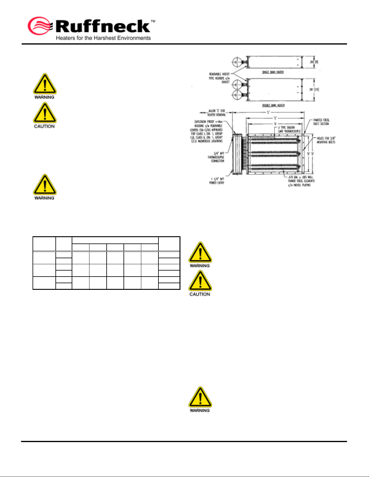
4.3 Verify that the nameplate voltage, phase, and wattage are
Duct Size No. of Weight
(W x H) Banks A B C D L kg (lbs)
610 x 305 1 610 305 686 381 927 41 (90)
(24 x 12) 2 (24) (12) (27) (15) (36½) 73 (160)
762 x 457 1 762 457 838 533 1080 61 (135)
(30 x 18) 2 (30) (18) (33) (21) (42½) 114 (250)
914 x 610 1 914 610 991 686 1232 82 (180)
(36 x 24) 2 (36) (24) (39) (27) (48½) 148 (325)
Dimensions
as ordered and are the same as the electrical power supply
available.
DO NOT CONNECT THE HEATER TO AN
ELECTRICAL SUPPLY VOLTAGE OTHER
THAN THAT SHOWN ON THE PRODUCT
NAMEPLATE.
REVIEW THIS MANUAL AND ALL DRAWINGS
CONTAINED WITHIN PRIOR TO
INSTALLATION, WIRING, OR OPERATION OF
THE HEATER.
5.0 DIMENSIONS AND INSTALLATION
The heater must be installed by qualified personnel in strict
compliance with the electrical code and hazardous locations
standards.
THE HEATER MUST BE INSTALLED IN A
HORIZONTAL DUCT SECTION ONLY.
IMPROPER ORIENTATION OF THE HEATER
COULD AFFECT THE SAFE AND RELIABLE
OPERATION OF THE HEATER.
5.1 HEATER DIMENSIONS
Table 1 - Heater Dimensions and Weights (See Fig. 1)
MI291 REV.3 Page 2 of 4
Figure 1 - RXDF Heater Dimensions
5.2 INSTALLATION
5.2.1 The heater is designed for installation in a horizontal duct
with the terminal boxes at the side. Improper orientation of the
duct heater could effect the safe and reliable operation of the heater.
Note: All dimension in millimeters (inches in brackets).
IMPROPER ORIENTATION OF THE HEATER
COULD AFFECT THE SAFE AND RELIABLE
OPERATION OF THE HEATER.
NEVER USE THE CONTROL HOUSINGS FOR
LIFTING OR MOVING THE HEATER AS THIS
COULD DAMAGE THE HEATING ELEMENTS
AND CONDUIT.
5.2.2 To install the heater, bolt the heater assembly into the
customer supplied ducting system. If necessary, reinforce with duct
supports to support the heater weight as shown in Table 1. Note
proper orientation of heater, as shown by the "TOP" and "AIRFLOW"
labels.
5.2.3 An explosion-proof pressure differential switch has been
supplied loose. Install the switch in a suitable location and with
proper orientation. Install tubing between the switch and the duct
using the appropriate port on the switch body (sensing high or low
pressure). Consult manufacturer's operation instructions included
with this manual.
THE PRESSURE DIFFERENTIAL SWITCH IS A
CRITICAL SAFETY COMPONENT. IMPROPER
INSTALLATION OF THE SWITCH MAY RESULT
IN HAZARDOUS CONDITIONS.
CCI Thermal Technologies Inc. 2721 Plymouth Drive, Oakville, ON L6H 5R5 Tel. (905) 829-4422 Fax (905) 829-4430
www.ccithermal.com
Page 3
MI291 REV.3 Page 3 of 4
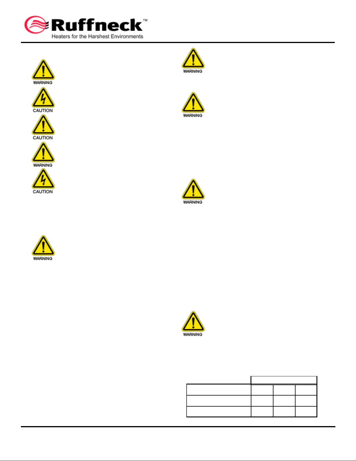
Temperature Code
T2D T3A T3B
He ate r Bank #1 (Inle t)
94 78 65
He ate r Bank #2 (Outle t)
125 100 83
High Lim it Set-Point (°C)
6.0 WIRING
Whenever hazardous materials are present,
ensure that the terminal housing covers,
plugs, etc., are secured (but not overtightened) before energizing the heater.
All circuits must be in the open position before
removing junction or terminal box covers.
Use supply wires suitable for 90°C. Supply
wires are to be fused with appropriately sized
HRC fusing.
Use approved conduit and conduit seals as
required by hazardous location standards.
Ensure that no power is connected to the
equipment prior to making any connections.
6.1 The heater is factory prewired to supply terminal blocks in
the heater terminal housing ready for direct connection to the power
supply. The heater also contains one (1) high limit thermocouple
per heating bank that must be wired to the control equipment.
After all connections have been made and
before starting up the system, ensure that all
housings, plugs, covers, etc. have been
installed.
7.0 STARTUP AND OPERATION
TO ENSURE SAFE AND RELIABLE
OPERATION, DO NOT EXCEED THE MAXIMUM
OUTLET TEMPERATURE OF 40°C AND DO
NOT ALLOW THE AIRFLOW TO DROP BELOW
THE MINIMUM AIRFLOW AS SHOWN ON THE
PRODUCT NAMEPLATE.
7.1 Turn on the airflow through the duct heater. Ensure that
the minimum airflow, as shown on the product nameplate, is
maintained at all times.
7.2 The field installed explosion-proof differential pressure
switch may require field adjustment. Consult manufacturer's
operation instructions included with this manual.
THE PRESSURE DIFFERENTIAL SWITCH IS A
CRITICAL SAFETY COMPONENT. IMPROPER
SETTING OF THE SWITCH MAY RESULT IN
HAZARDOUS CONDITIONS.
7.3 Apply power to the control panel.
7.4 Turn the control on/off switch to "On".
6.2 To wire the heater to the control equipment, make the
following connections at the connection points indicated on the
assembly drawing:
a) 1¼" NPT conduit entries have been provided in each heater
terminal housing for wiring the power supply and ground to
the heaters. Connect the heating bank(s) to the contactor(s)
in the control panel.
b) ¾" NPT conduit entries have been provided on each heater
bank for wiring the J type high limit thermocouple(s) to
Certified, manual-reset high limit controller(s) in the control
panel. Using appropriate thermocouple extension wire,
connect the thermocouple(s) to the high limit controllers,
ensuring proper connection of the positive and negative
leads.
c) Connect the "Normally Open" contacts of the supplied
pressure differential switch to the interlocks in the control
circuit.
CCI Thermal Technologies Inc. 2721 Plymouth Drive, Oakville, ON L6H 5R5 Tel. (905) 829-4422 Fax (905) 829-4430
For double bank heaters, Heater Bank #1 is
defined as the inlet bank and Heater Bank #2
is defined as the outlet bank. This distinction
is important in order to ensure proper high
limit set limit set points must be set in the
field. Table 2 gives the maximum high limit
set points for safe operation of the heater. For
initial start-up, set the high limit controllers
to the values indicated in Table 2 and lock in
place.
www.ccithermal.com
7.5 Set the temperature controller to the desired set point. Do
not exceed the maximum outlet temperature of 40°C.
7.6 Ensure that the temperature controller is working properly.
Consult the manufacturer's operation instructions supplied with the
temperature controller.
7.7 Except when purchasing a control panel to accompany your
RXDF heater, the high limit set points must be set in the field. Table
2 gives the maximum high limit set points for safe operation of the
heater. For initial start-up, set the high limit controllers to the values
indicated in Table 2.
TO PREVENT UNSAFE OPERATION OF THE
HEATER, DO NOT EXCEED THE MAXIMUM
HIGH-LIMIT SET POINTS. OPERATION OF
THE HEATER WITH HIGH LIMIT SET POINTS
GREATER THAN THOSE SHOWN IN TABLE 2
CREATES A SIGNIFICANT RISK OF
EXPLOSION.
Table 2 - Maximum High Limit Set Points
Page 4
MI291 REV.3 Page 4 of 4
8.0 OVERHEAT PROTECTION
8.1 The heater is equipped one (1) high limit thermocouple
per heating bank to sense the heating element sheath
temperature. Each high limit thermocouple must be wired to a
separate CSA C/US Certified, manual-reset high limit controller in the
control panel. The set point of the controller(s) must be locked, and
not exceed the values given in Table 2.
8.2 In the event of fan failure, excessive dust buildup, or
restricted airflow, the heater temperature may rise, causing the limit
controls to open and break the power supply to the heater.
CYCLING OF THE HEATER ON THE HIGH
LIMITS SHOULD NOT BE PERMITTED. Should
this occur, the system should be inspected to
determine the cause of the cycling, and the
condition must be corrected before regular
operation is resumed.
9.0 MAINTENANCE
DISCONNECT ALL POWER TO THE
EQUIPMENT PRIOR TO SERVICING.
9.1 Periodically inspect the heater installation to ensure that all
connections, fitting, plugs, screws, covers, etc. are tight and free of
corrosion.
9.2 Check the surface of the duct section and terminal boxes for
dust and debris, especially after seasonal shutdowns. Clean with a
blast of air or vacuum.
9.3 Check the surface of the finned elements for dust and debris.
Clean with a blast of air.
9.4 Ensure that all fuses are in proper working order.
9.5 Maintain the pressure differential switch in accordance with
the manufacturer's instructions.
9.6 Field repair of the heater should not be undertaken. In the
event that the heater must be repaired, contact the factory.
10.0 DRAWINGS AND LITERATURE
10.1 LITERATURE
The following manufacturer's literature has been included with this
manual:
a) Explosion-Proof Pressure Differential Switch
11.0 FIELD SERVICABILITY
The RXDF explosion-proof duct heater is not field-serviceable. If
your heater requires servicing, please consult the factory.
WARRANTY
CCI Thermal Technologies Inc. warrants to the purchaser of each new product that any part thereof which proves to be defective in
material or workmanship under normal use within 24 months of the date of shipment or 12 months from the date of start of operation
(whichever occurs first) will be repaired or replaced without charge. Any such defect should be brought to the attention of the
company's office from which the product was purchased, which is authorized to furnish or replacement within the terms of this
warranty.
The Company will not be responsible for any expenses incurred in installation, removal from service, transportation cost, or damages
of any type whatsoever, including incidental or consequential damages. Some states or provinces do not allow exclusion or limitation
of incidental or consequential damages so the preceding exclusion or limitation may not be applicable to you.
Since we cannot anticipate or control the condition under which our products may be used, we accept no responsibility for the safety
and suitability of our products when used alone or in combination with other products. Tests for safety and suitability of the products
should be done by the user.
This warranty will not apply if, in the judgment of the Company damage or failure has resulted from accident, alteration, misuse,
abuse or operation on an incorrect power supply. The foregoing is in lieu of other warranties expressed or implied. CCI Thermal
Technologies Inc. neither assumes no authorizes any person to assume for it any other obligation, during transportation, installation
and operation or liability in connection with the said product.
Since the paint finish may be damaged during installation and operation, no warranty applies to such paint finish except for manufacturing
defects.
Heaters are not guaranteed against damage caused by corrosion.
CCI Thermal Technologies Inc. 2721 Plymouth Drive, Oakville, ON L6H 5R5 Tel. (905) 829-4422 Fax (905) 829-4430
www.ccithermal.com
 Loading...