

Page 1

ISO 9001
Owner’s Manual
FX5 Series
Electric Forced Air Heaters for Hazardous Locations
This manual covers the installation, maintenance, repair and replacement parts.
APPROVED LOCATIONS
FX5 - 480 3 60 - 350 - W T, D, P, S, H, C, A, U
The Electric Forced Air Heaters are cULus listed
certified for the following locations:
Class I, Divisions 1 & 2, Groups C & D;
Class II, Division 1, Groups E, F, & G;
Class II, Division 2 , Groups F & G;
Class I, Zones 1 & 2, Groups IIA & IIB;
Temperature Code T3B 329˚F (165˚C)
(50 Hz & 60 Hz Models)
For details of hazardous locations with potential for
explosion, refer to the Canadian Electrical Code, Part 1,
Section 18 or National Electrical Code articles 500-516.
WARNING!
READ ALL IMPORTANT INFORMATION NOTICES ON PAGES 2, 3 & 4.
Part No. 9714.Rev.8.00 Issue Date: November 2013 Printed in Canada
Ruffneck™ and VacuCore® are registered trademarks of CCI Thermal Technologies Inc.
Copyright© 2013. All rights reserved.
5th GENERATION
MODEL
SERIES
HEATER
VOLTAGE
PHASE
KILOWATTS
HERTZ
HEATER
WELDED
CORE
OPTIONS
T - Built-in thermostat
D - Built-in disconnect switch
P - Built-in pilot light
S - 3-way switch
H - Unit with high ”off”
(deenergized)
ambient temperatures
C - Heresite® coating
A - Stainless-steel cabinet
U - Continuous Fan
C US
Listed
Page 2

Preventative Maintenance Grid
X X X
X X X
X X X
X X X
HEATER MAINTENANCE CHECKLIST
Photocopy
For Electric Forced Air Heaters
Heater Model: _________________________ Serial No.: ___________________________
Date of Maintenance: ___________________ Maintenance Done By: _________________
Comments: _________________________________________________________________
__________________________________________________________________________
WARNING
Disconnect heater from power supply at integral disconnect or fuse box before opening enclosures or servicing heater.
Lock the switch in the “OFF” (open) position and/or tag the switch to prevent unexpected power application.
IF INTEGRAL DISCONNECT IS BEING SERVICED, verify that power has been disconnected at fuse box or main panel.
Lock the switch in the “OFF” (open) position and/or tag the switch to prevent unexpected power application.
This heater should only be serviced by personnel with heating and hazardous location equipment experience.
PREVENTATIVE MAINTENANCE GRID
this page
for reuse.
Annual
Start Up
1 Month 3 Month 12
Clean:
Finned Tubes
Regular Service Severe Service
Fan
Fan Guard
Motor
Louvers
Electrical
Check all terminal
connections and
conductors.
Inspect contactor
contacts.
Check Fuses The Correct fuse rating and type
Mechanical
Check for fluid
leakage
Check all enclosures The interiors of each enclosure
Check motor shaft
bearing play
Remove dust using compressed air.
Do not Spray with water or
solvents.
Do not immerse in water or
solvents.
Tighten loose connections.
Replace conductors with damaged
insulation & frayed wiring. For
drilling rigs, this should be done
with every rig re-location.
If badly pitted, burned or welded
shut, replace with factory supplied
contactor. For drilling rigs, this
should be done with every rig relocation.
are printed on the circuit board.
Always ensure a backup fuse is
available on the PCB. For drilling
rigs, this should be done with
every rig re-location.
Inspect the Pressure Release Valve
label indicator for signs of rupture
and degradation. If any fluid
leakage occurs from the heater,
disconnect it from the power
supply and have the core replaced
immediately. For drilling rigs,
this should be done with every
rig re-location.
must be clean, dry and free of
foreign materials. For drilling
rigs, this should be done with
every rig re-location.
If the motor does not run quietly
and smoothly and has excessive
play replace the motor. For
drilling rigs, this should be done
with every rig re-location.
X
X X X X
X X
Month
Annual
Start Up
1 Month 3 Month 12
X X
Month
2
Page 3
PERIODIC (before and as required during heating season)
1. CLEAN Finned Tubes 2. CHECK Motor for smooth, quiet operation
Fan Louvers for proper angle and tightness
Fan Guard All explosion-proof covers for tightness
Motor Pressure relief device for signs of
Louvers leakage. See Figure 1 and refer to the
ANNUAL Section (see below) item 2 for
further instructions
Remove dust using compressed air. Do not spray with water or solvents.
Do not immerse in water or solvents.
ANNUAL (before heating season)
1. ELECTRICAL
Check all terminal connections and conductors. Tighten loose connections. Conductors with damaged
insulation must be replaced.
Inspect contactor contacts. If badly pitted, burned or welded shut, replace with factory supplied contactor. For
severe duty conditions such as arctic duty or drilling rigs, CCI Thermal recommends the contactor be replaced
every two years.
Check fuses. Fuse rating and type are on printed circuit board. Correct fuse must be in the active fuse clip. It is
recommended that a spare fuse be stored in the spare fuse clip.
Check all explosion-proof conduits. Replace damaged conduits. All threaded conduit connections must have
a minimum 5 turns engagement. Straight threaded conduit must protrude a minimum of 1/16” (1.6mm) inside
enclosures. Taper threaded connections must be at least hand tight.
Check electrical resistance on all load side legs. Reading should be balanced (± 5%).
Photocopy
this page
for reuse.
2. MECHANICAL
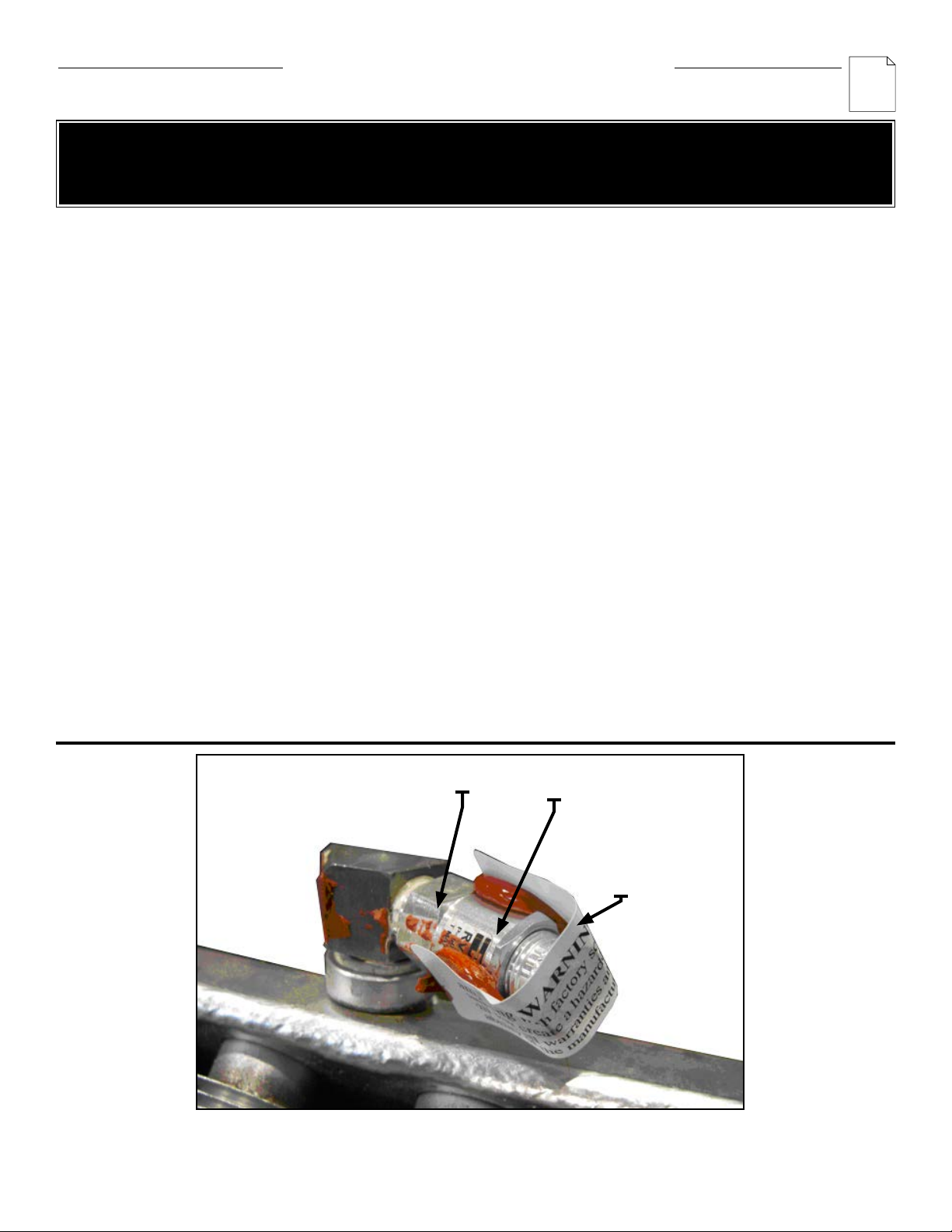
Check for fluid leakage. The heater core is vacuum charged and contains propylene glycol. Inspect the
Pressure Relief Valve label indicator for signs of rupture and degradation. If the paper is torn, disintegrated or
otherwise compromised this is an indication that fluid has leaked from the core. If any fluid leakage occurs from
the heater, disconnect it from the power supply and have the core replaced. A factory supplied exchange core
can be shipped immediately from stock. Refer to the "Repair and Replacement" section for details.
Check all enclosures. Interior of enclosures must be clean, dry and free of foreign materials. Threaded covers
must be installed and hand tight.
Note: Enclosure joints are metal to metal. Do not use gasket material or sealant in joints. A grease is applied to
the joints at the factory and should be left intact.
Check motor shaft bearing play. Replace motor if play is excessive, or if motor does not run quietly and
smoothly. Motor bearings are permanently lubricated.
Check fan. Replace immediately if cracked or damaged.
Check louvers. Louver screws should be tight. Louvers shall not be fully closed or override stops.
Check the tightness of all hardware. All nuts and bolts, including mounting hardware, must be tight.
Turn heater on for a minimum of five minutes. Check for warm air exiting heater through louvers. Crackling or
pinging noises within heater during start-up are normal.
For assistance, please call
Toll Free: 1-800-661-8529 (24 hrs)
U.S. & Canada
3
Page 4
IMPORTANT NOTICES
WARNING
Read and adhere to the following. Failure to do so may result in severe or fatal injury.
WARRANTY WILL BE VOID
Photocopy
this page
for reuse.
1. Read and follow all instructions in this manual.
2. Heater is to be used only in atmospheres having an
ignition temperature higher than the heater’s maximum
rated operating temperature as shown on the heater
data plate. Refer to applicable electrical codes for
additional information.
3. Heater to be used only in the hazardous locations
indicated on the heater’s data plate.
4. Heater is for dry indoor use only. Do not immerse in
water. Do not store or use in areas exposed to rain
or snow.
5. Heater is to be connected and serviced only by a
qualified electrician experienced with hazardous
location equipment.
6. Installation and wiring of the heater must adhere to
all applicable codes.
7. Disconnect heater from power supply at integral
disconnect or fuse box before opening enclosures or
servicing heater. Lock the switch in the “OFF” (open)
position and/or tag the switch to prevent unexpected
power application. IF INTEGRAL DISCONNECT IS
BEING SERVICED, verify that power has been
disconnected at fuse box or main panel. Lock the
switch in the “OFF” (open) position and/or tag the
switch to prevent unexpected power application.
8. This heater is equipped with a single bimetal
overtemperature high-limit. It is of the automatic reset
type and therefore the heater may restart without
warning. The heater is not to be operated with the
high-limit disabled or disconnected from the
control circuit.
9. Venting pressure of the pressure relief valve is factory
set. Do not tamper with lock nut.
10. Do not tamper or remove warning label indicator on the PRV.
11. Operate the heater only while it is permanently
mounted in an upright position. Refer to the
“Installation - Mechanical” section for details.
12. Heater must be kept clean. When operating in a dirty
environment, regularly clean the finned tubes, fan, and
fan guard. Follow the recommended maintenance
procedures. Refer to the “Heater Maintenance
Checklist” section for details.
13. The heater core is vacuum charged and contains
propylene glycol. If any fluid leakage occurs from the
heater, disconnect it from the power supply and have
the core replaced with a factory supplied core. Refer to
the “Repair and Replacement” section for details.
14. Do not operate the heater with any of the louvers fully
closed or overriding their stops.
15. Do not operate the heater in atmospheres corrosive to
steel or aluminum.
16. Do not operate heater in ambient temperatures above
104°F (40°C).
17. Use factory approved replacement parts only.
18. See applicable electrical codes for seal requirements in
field installed conduits. Factory installed conduits
require no further sealing.
19. Crackling or pinging noises within the heater core
during start up may occur. This is normal.
20. Air discharge near the bottom of the heater may be
warmer than the top. This is normal.
21. If there are any questions or concerns regarding the
heater, contact the factory. Refer to the last page of
this manual for details.
PRV
PRV LOCK NUT
PRESSURE RELIEF
VALVE (PRV) LABEL
INDICATOR
FIGURE 1
4
Page 5

HEATER LOCATIONS
EXTERIOR WALL
EXTERIOR
WALL
FIGURE 2
TROUBLESHOOTING TIPS
1.0 Heater is not operating
1.1 Check all fuses in heater control box.
1.2 Check remote disconnect switch and circuit breaker.
1.3 Check voltage supplied to the heater – refer to the heater data plate for voltage requirements.
1.4 Check thermostat by turning it and check continuity with a multimeter.
1.5 Check the condition of the disconnect switch if the heater is so equipped. Measure continuity through the disconnect
by engaging the switch.
1.6 Verify that there is a jumper wire present between terminals 5 and 6 on the terminal block located in the control box.
2.0 Contactor is chattering
2.1 Check supply voltage.
2.2 Check wiring connections. Tighten all loose electrical connections.
2.3 Check thermostat for continuity (See 1.4). If thermostat does not break continuity replace thermostat.
3.0 Contactor is burned or welded
3.1 Check the contactor for burn marks and blackening. Replace the contactor.
3.2 Check incoming power to the heater to ensure there are no voltage uctuations.
4.0 Heat exchanger is dirty
4.1 Clean the heat exchanger using compressed air.
5.0. PRV has released
5.1 If there are signs that the PRV has released uid, PRV indicator is broken, blackening around the PRV exit hole, or
there are uid stains visible on the top louver, shut the unit down immediately.
5.2 Check for restricted air ow, bad motor, broken thermostat or malfunctioned high limit.
6.0 Heater is cold on top and warm on bottom
6.1 The core may have lost its vacuum. Check the PRV for signs of loss of uid and verify that the PRV label indicator is
not broken. If PRV has released, send the unit in for repair or replace the core.
6.2 If the PRV does not indicate loss of uid, the heater should operate normally. Check for loss of uid on a weekly basis
as a minimum.
6.3 The ambient temperature may be too low. If the ambient temperature is very cold the top of the core will be colder
7.0 Unit cycles on high limit – unit turns on and turns off within less than 5 minutes.
8.0 The Ground Fault Interrupter (GFI) trips on the main panel, or heater blows fuses.
9.0 The fan is turning but very little air comes from the front of the heater.
than the bottom – this is normal.
7.1 Check and see if the PRV has released uid. Core may have lost most or all of its uid. If PRV has released, send the
unit in for repair or replace core.
7.2 The core may be dirty, fan may not be working or may be turning the wrong way (the fan must rotate clockwise as
seen from the front of the unit) objects may be stuck in the heat exchanger for drying or warming up – remove any
items from the exchanger.
8.1 Check that you have a fuse of the proper amperage rating.
8.2 Check for loose or frayed wiring.
8.3 If condition is not observable, send heater in for repair.
8.4 Change sensitivity of GFI.
9.1 Check fan rotation and ensure that the fan turns clockwise as seen from the front of the heater. Refer to the Installation
section below for more information.
9.2 Check motor winding resistance and verify that they are balanced.
9.3 Check fan blade set screws to ensure fan blade is not loose on the motor shaft.
INSTALLATION
The installation instructions provide a general guideline for the installation and wiring of the heater.
All applicable codes must be adhered to.
MECHANICAL
LOCATION
For optimum heating, the heater should be installed as follows:
1. There are no obstructions that may impede the heater’s air
inlet or discharge.
2. The air discharge is directed into open areas and not
at occupants.
3. The air discharge is not directed at a thermostat.
4. The air discharge is directed across areas of heat loss, such
as doors and windows (see Figure 2).
5. The air discharge is directed along and at a slight angle
toward exterior walls (see Figure 2).
6. If equipment freeze protection is important, direct air
discharge at equipment.
7. Air discharge streams support each other and create a
circular air flow. It is not required that the heater’s air
throw reaches the next heater (see Figure 2).
5
Page 6
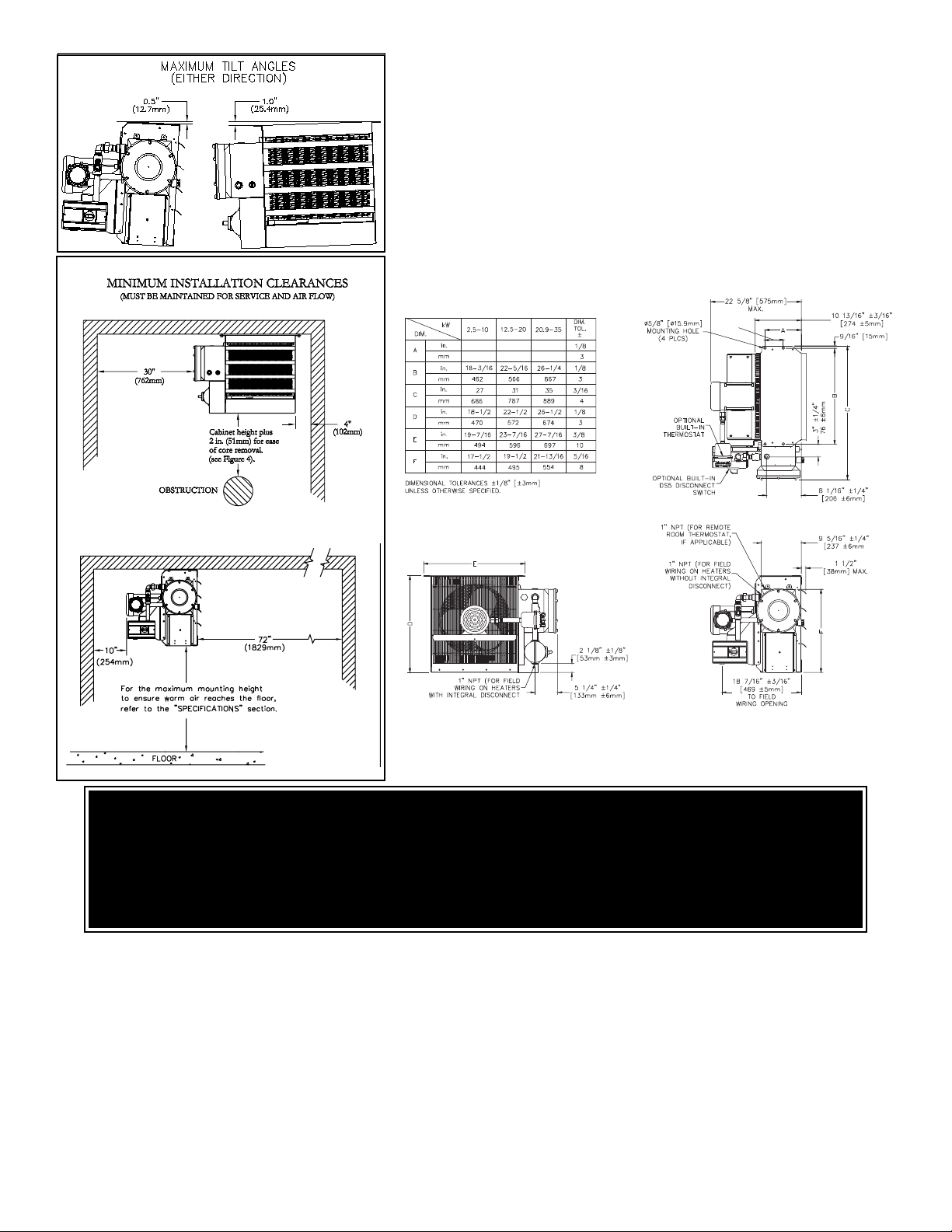
FIGURE 3
MOUNTING
1. The heater must be permanently mounted in a level,
upright position for operation. See Figures 3, 4, and 5
for maximum tilt angles, installation clearances, and
physical dimensions. For ease of installation, a variety
of mounting kits are available from the factory.
2. The mounting structure must be strong enough to:
a. support the heater’s weight, refer to the
“Specifications” section,
b. provide sufficient stiffness to prevent excessive
vibration, and
c. withstand harsh situations such as transportable
installations.
3 3/4”
7.75 7.75 7.75
198 198 198
FIGURE 4
ELECTRICAL
WARNING
Disconnect heater from power supply at integral disconnect or fuse box before opening enclosures or servicing
heater. Lock the switch in the "OFF" (open) position and/or tag the switch to prevent unexpected power application.
IF INTEGRAL DISCONNECT IS BEING SERVICED, verify that power has been disconnected at fuse box or main
panel. Lock the switch in the "OFF" (open) position and/or tag the switch to prevent unexpected power application.
Installation and wiring of the heater must adhere to all application codes.
GENERAL
1. Use only copper conductors and approved explosion-
proof wiring methods during installation. Refer to the “Technical
Data” table and heater data plate for conductor rating.
2. External overcurrent protection is required. Refer to the
“Technical Data” table and heater data plate for voltage,
frequency amperage, and phase. Supply voltage is to be within
10% of the data plate voltage.
3. The heater must be installed by qualified personnel in strict
compliance with electrical codes.
4. All heaters come factory prewired and ready for direct
connection to the power supply leads.
5. The heater must be individually fused, preferably with Class J
time-delay fuses for maximum safety. Unless stated otherwise in
your local code, fuse size shall be 125% of line current or next
size larger.
6
FIELD WIRING
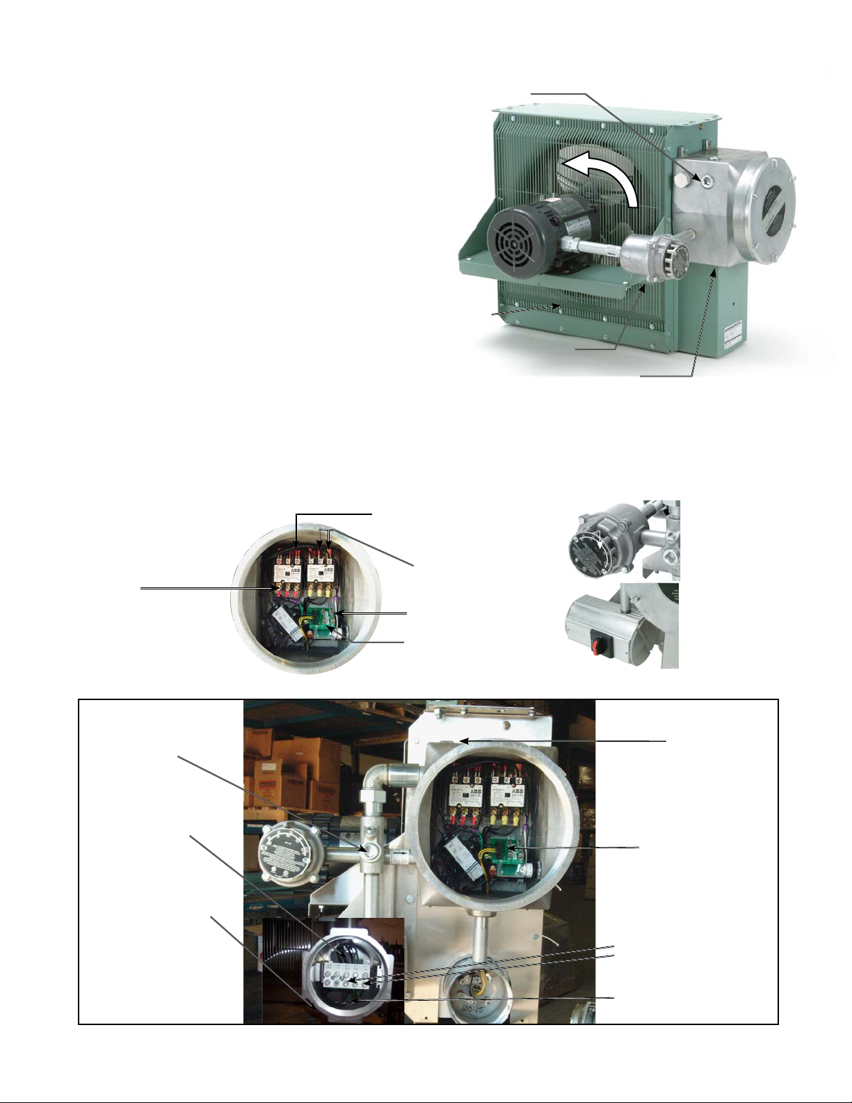
1. The supply conductors, ground conductor, and room thermostat
conductors (see point 2, page 5) all pass through the 1” NPT
opening (see Figure 6) and are to be wired into the control
enclosure (see Figure 7A).
2. Heater may be supplied with a factory installed built-in room
thermostat (see Figure 8). On heaters not supplied with this
option, it is recommended that a remote room thermostat be
used. Connect the remote room thermostat conductors to the
printed circuit board terminal block marked “TSTAT”.
Any thermostat used with this heater must:
a. be of an explosion-proof type,
b. be rated 125 V minimum,
c. have a minimum 2 amp capacity, and
d. open on temperature rise.
FIGURE 5
Page 7
3. Heater may be supplied with a factory installed built-in integral
disconnect. (See Figure 7B)
Field Wiring for Integral Disconnect:
a. Power Supply conductors and Ground conductor pass through
1"NPT opening of Disconnect Enclosure (see Figure 7B).
Supply conductors to be wired to Disconnect Switch inside.
Ground conductor to be wired to Ground Lug fastened to inside
of Disconnect Enclosure.
b. If applicable, Remote Room Thermostat conductors pass
through 3/4"NPT opening (see Figure 7b) and are to be wired to
printed circuit board terminals marked “T’STAT”.
c. To reduce risk of ignition of hazardous atmospheres, conduit
runs must have a sealing fitting connected within 18 inches
(457 mm).
Factory installed conduits require no further sealing. Integral
Disconnect is sealed at factory.
4. The internal grounding terminal in the control enclosure (or in the
integral disconnect enclosure when this option is provided) shall
be used as the equipment grounding means. An external bonding
terminal is provided for a supplementary bonding connection where
local authorities permit or require such a connection.
FINAL INSPECTION
1. Before application of electrical power:
a. Check that all connections are secured and comply with the
applicable wiring diagram (see Figure 9) and code requirements,
b. Confirm that the power supply is compatible with the data plate
rating of the heater,
c. Remove any foreign objects from the heater,
d. Install all covers and verify that all enclosures are well secured, and
e. Ensure that the fan rotates freely. See Figure 6 for proper direction
of fan rotation.
Control Enclosure & Field Wiring
Contactor load
side terminals, this
side for factory
wiring only.
Connect supply conductors
to this side of contactor.
1“ NPT opening
for field wiring
Air
intake
For a 1-phase
heater, use these
contactor lugs.
Active and spare
fuses (see parts list)
Printed circuit board’s
terminal block
Rear View of Heater
Air exits through
louvers.
Fan
rotation
Motor
junction box
Control enclosure
and cover
Do not install conduit below heater (see Figure 3).
FIGURE 6
Optional factory
installed built-in
room thermostat.
Optional factory
installed built-in
disconnect.
Optional Built-in Disconnect
& Field Wiring
Sealed at Factory
Switch load side
terminals, this
side for factory wiring
only.
1" NPT
(Power Supply)
FIGURE 7A
FIGURE 8
3/4" NPT
(Remote Room
Thermostat
if applicable)
Terminals marked
“T’STAT”
For a 1-phase heater use these
Switch terminals
Connect Supply Conductors to
this side of Switch
FIGURE 7B
7
Page 8
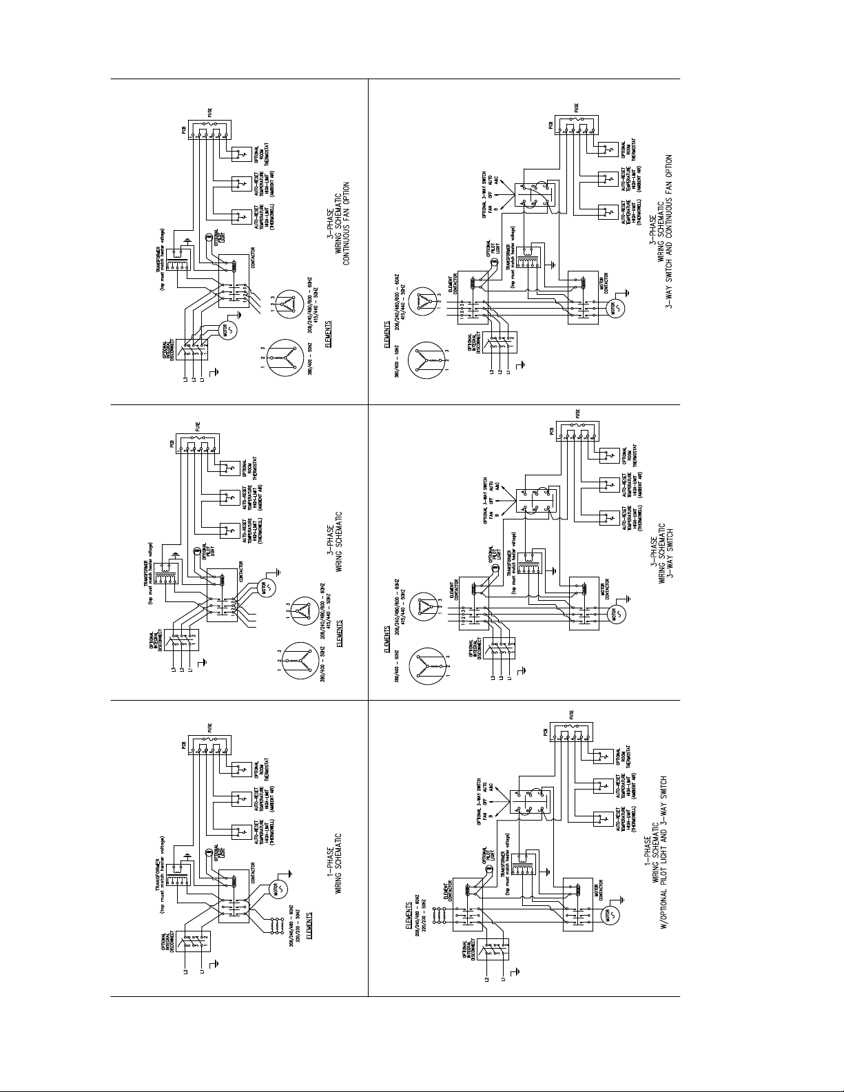
FIGURE 9
8
Page 9
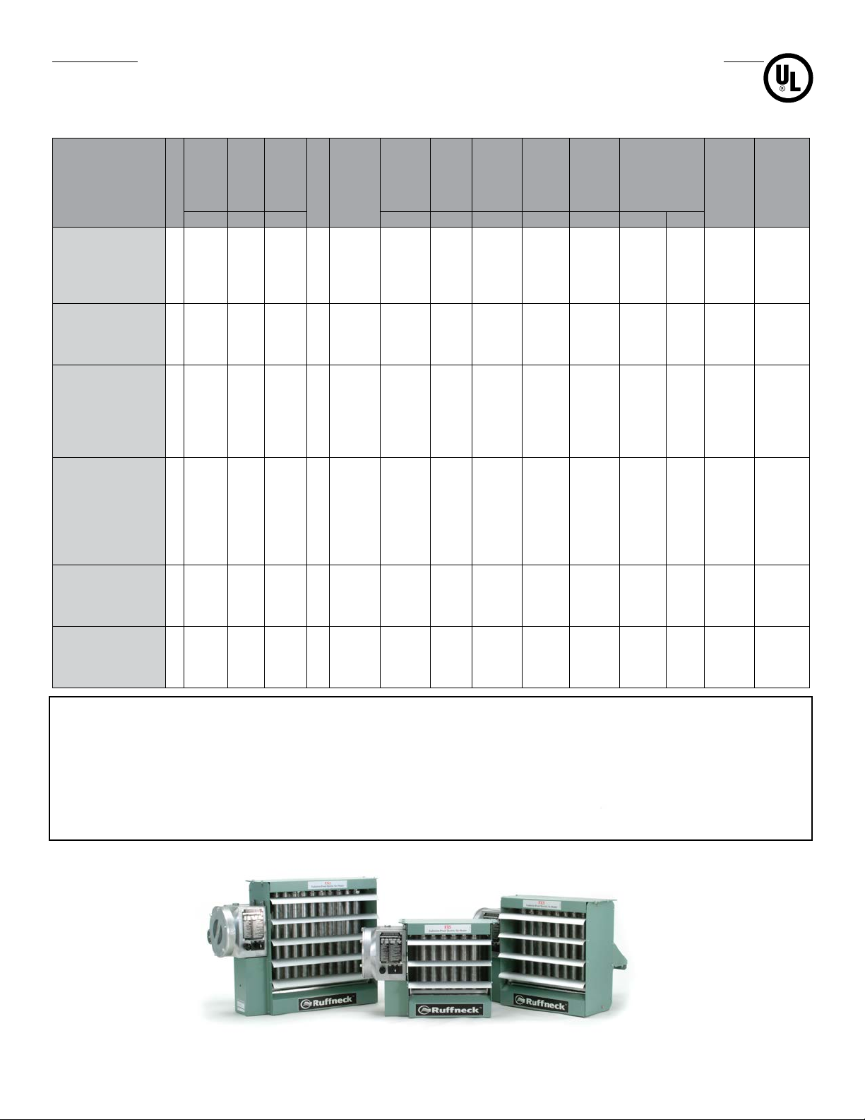
FX5 TECHNICAL DATA FOR 50 HZ
ELECTRIC HEATERS
Temperature
Model
Wattage
Total
Current
Circuit
Minimum
Note
(CFM) (V) (kW) (W) (A) (A) (AWG) (A) °F °C
Air Flow
Voltage
Nominal
Wattage
Phase
Nameplate
Max. Motor
Heater
Current
Wire
Supply
Ampacity
Maximum
FX5-220150-025 400 220 2.5 1 2.7 2270 11.4 14.3 14 15 19.8 11.0 12122 3618
FX5-220150-042 400 220 4.2 1 2.7 3950 19.1 23.9 10 25 33.2 18.4 12123 3618
FX5-220150-063 700 220 6.3 1 2.7 6050 28.6 35.8 8 40 28.5 15.8 12124 3618
FX5-220150-084 700 220 8.4 1 2.7 8140 38.2 47.8 6 50 37.9 21.1 12125 3619
FX5-220150-126 * 1450 220 12.6 1 1.4 12100 57.3 71.6 2 75 27.5 15.3 12126 3619
FX5-230150-028 400 230 2.8 1 2.7 2480 12.2 15.3 12 20 22.1 12.3 12122 3618
FX5-230150-046 400 230 4.6 1 2.7 4310 20.0 25.0 10 25 36.4 20.2 12123 3618
FX5-230150-069 700 230 6.9 1 2.7 6610 30.0 37.5 8 40 31.2 17.3 12124 3618
FX5-230150-138 * 1450 230 13.8 1 1.4 13200 59.9 74.9 2 80 30.1 16.7 12126 3619
FX5-380350-025 400 380 2.5 3 0.7 2270 3.8 4.8 16 5 19.8 11.0 12122 3618
FX5-380350-042 400 380 4.2 3 0.7 3950 6.4 8.0 16 10 33.2 18.4 12123 3618
FX5-380350-063 700 380 6.3 3 0.7 6050 9.6 12.0 14 15 28.5 15.8 12124 3618
FX5-380350-084 700 380 8.4 3 0.7 8140 12.8 16.0 12 20 37.9 21.1 12125 3618
FX5-380350-125 1450 380 12.5 3 0.7 12100 19.0 23.8 10 25 27.3 15.1 12126 3618
FX5-380350-209 3000 380 20.9 3 1.0 20300 31.8 39.8 8 40 22.0 12.2 12128 3618
FX5-400350-028 400 400 2.8 3 0.7 2480 4.0 5.0 16 5 22.1 12.3 12122 3618
FX5-400350-046 400 400 4.6 3 0.7 4310 6.6 8.3 16 10 36.4 20.2 12123 3618
FX5-400350-069 700 400 6.9 3 0.7 6610 10.0 12.5 14 15 31.2 17.3 12124 3618
FX5-400350-093 700 400 9.3 3 0.7 8900 13.4 16.8 12 20 42.0 23.3 12125 3618
FX5-400350-139 1450 400 13.9 3 0.7 13200 20.1 25.1 10 30 30.3 16.8 12126 3618
FX5-400350-185 1450 400 18.5 3 0.7 17800 26.7 33.4 8 35 40.3 22.4 12127 3618
FX5-400350-231 3000 400 23.1 3 1.0 22200 33.3 41.6 8 45 24.3 13.5 12128 3619
FX5-415350-037 400 415 3.7 3 0.7 3510 5.1 6.4 16 10 29.3 16.3 12130 3618
FX5-415350-075 700 415 7.5 3 0.7 7240 10.4 13.0 14 15 33.9 18.8 12132 3618
FX5-415350-149 1450 415 14.9 3 0.7 14500 20.7 25.9 10 30 32.5 18.1 12134 3618
FX5-415350-224 3000 415 22.4 3 1.0 21800 31.2 39.0 8 40 23.6 13.1 12136 3618
FX5-440350-042 400 440 4.2 3 0.7 3950 5.5 6.9 16 10 33.2 18.4 12130 3618
FX5-440350-084 700 440 8.4 3 0.7 8140 11.0 13.8 14 15 37.9 21.1 12132 3618
FX5-440350-168 1450 440 16.8 3 0.7 16300 27.5 34.4 8 35 36.6 20.4 12134 3618
FX5-440350-210 3000 440 21.0 3 1.0 20300 27.5 34.4 8 35 22.1 12.3 12135 3618
Rise
Fuse Size
C US
Core Kit
Contactor
Part Number
Part
Number
NOTES:
* Exceeds the 48 Amp Circuit Limit of NEC 424-22. DS5 not available for these units.
1. Minimum conductor size for 86˚F (30˚C) ambient. Derate conductor for ambient temperature. Use minimum 194˚F (90˚C) insulation.
2. Heater is functioning normally if at rated voltage the amp draw is within 10% of the value in this table.
3. Operation at lower voltages will result in reduced heat output and amp draw
4. Add "T" to model number when adding a built-in thermostat
5. Add "D" to model number when adding a built-in disconnect switch
6. Add "P" to model number when adding a built-in pilot light
7. Add "S" to model number when adding a 3-way switch
8. Add "H" to model number for units with high "off" (deenergized) ambient temperatures
9. Add "U" to model number for units with continuous fan option.
10. Add "A" to model number for units with stainless steel cabinet.
9
Page 10
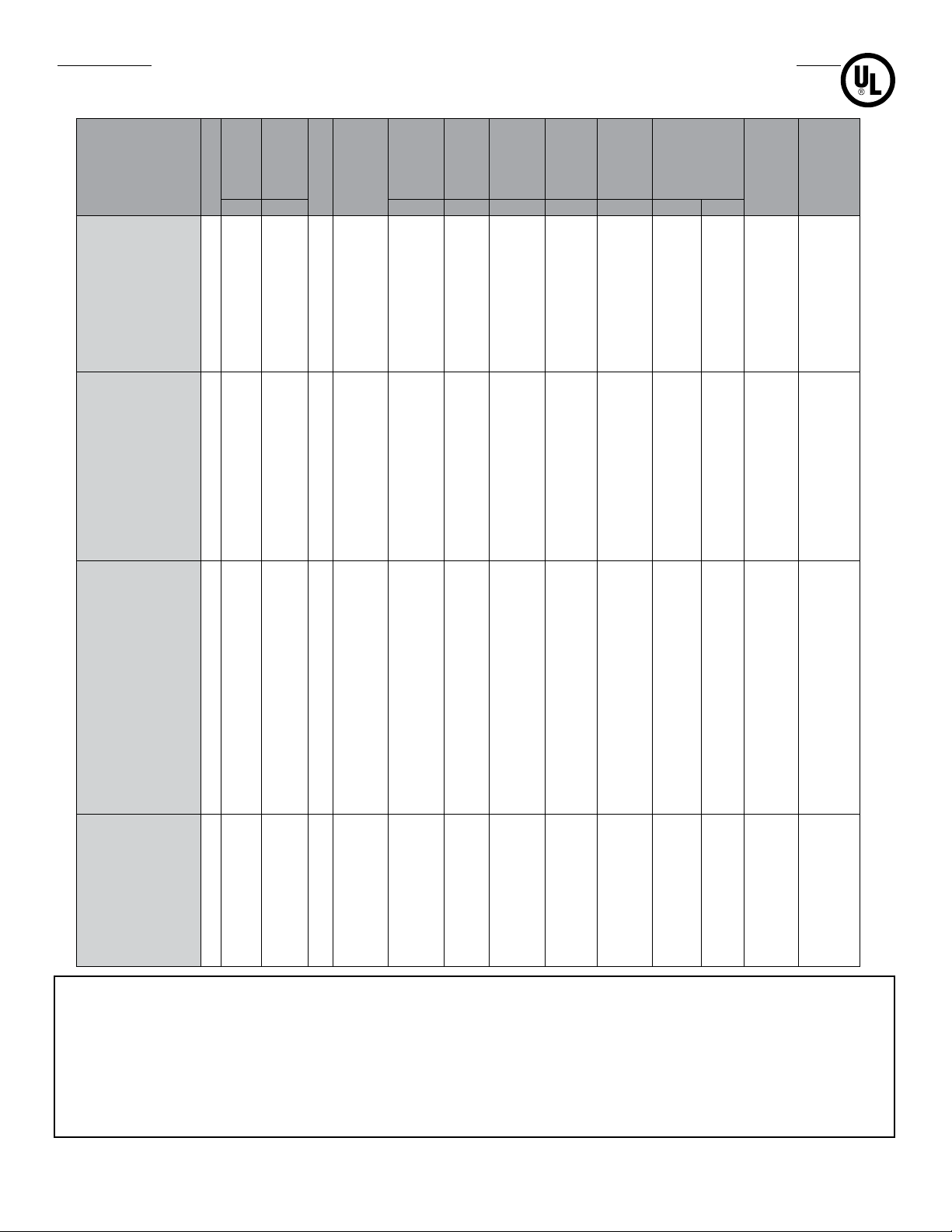
FX5 TECHNICAL DATA FOR 60 HZ
ELECTRIC HEATERS
Temperature
Model
Wattage
Total
Current
Circuit
Minimum
Note
Voltage
(V) (kW) (W) (A) (A) (AWG) (A) °F °C
Nominal
Wattage
Phase
Max. Motor
Heater
Current
Nameplate
Wire
Supply
Ampacity
Maximum
FX5-208160-030 208 3.0 1 2.7 2700 14.4 18.0 12 20 19.0 10.5 12116 10557
FX5-208160-050 208 5.0 1 2.7 4700 24.0 30.0 10 30 31.6 17.6 12117 10557
FX5-208160-075 208 7.5 1 2.7 7200 36.1 45.1 6 50 27.9 15.5 12118 10557
FX5-208160-100 * 208 10.0 1 2.7 9690 48.1 60.1 4 70 37.2 20.7 12119 10558
FX5-208360-030 208 3.0 3 1.4 2700 8.3 10.4 14 15 11.2 6.2 12116 10557
FX5-208360-050 208 5.0 3 1.4 4700 13.9 17.4 12 20 18.6 10.3 12117 10557
FX5-208360-075 208 7.5 3 1.4 7200 20.8 26.0 10 30 27.9 15.5 12118 10557
FX5-208360-100 208 10.0 3 1.4 9700 27.8 34.8 8 35 37.2 20.7 12119 10557
FX5-208360-150 208 15 3 1.4 14400 41.6 52.0 6 60 27.1 15.1 12120 10557
FX5-240160-030 240 3.0 1 2.7 2700 12.5 15.6 12 20 19.0 10.5 12122 10557
FX5-240160-050 240 5.0 1 2.7 4700 20.8 26.0 10 30 31.6 17.6 12123 10557
FX5-240160-075 240 7.5 1 2.7 7200 31.3 39.1 8 40 27.9 15.5 12124 10557
FX5-240160-100 240 10.0 1 2.7 9700 41.7 52.1 6 60 37.2 20.7 12125 10557
FX5-240160-150 * 240 15.0 1 1.4 14400 62.5 78.1 2 80 27.1 15.1 12126 10558
FX5-240360-030 240 3.0 3 1.4 2700 7.2 9.0 14 15 19.0 10.5 12122 10557
FX5-240360-050 240 5.0 3 1.4 4700 12.0 15.0 14 15 31.6 17.6 12123 10557
FX5-240360-075 240 7.5 3 1.4 7200 18.0 22.5 10 25 27.9 15.5 12124 10557
FX5-240360-100 240 10.0 3 1.4 9700 24.1 30.1 8 35 37.2 20.7 12125 10557
FX5-240360-150 240 15.0 3 1.4 14400 36.1 45.1 6 50 27.1 15.1 12126 10557
FX5-240360-200 * 240 20.0 3 1.4 19400 48.1 60.1 4 70 36.1 20.1 12127 10558
FX5-480160-030 ° 480 3.0 1 1.3 2700 6.3 7.9 14 15 19.0 10.5 12129 10557
FX5-480160-050 ° 480 5.0 1 1.3 4700 10.4 13.0 14 15 31.6 17.6 12130 10557
FX5-480160-075 ° 480 7.5 1 1.3 7200 15.6 19.5 12 20 27.9 15.5 12131 10557
FX5-480160-100 ° 480 10.0 1 1.3 9700 20.8 26.0 10 30 37.2 20.7 12132 10557
FX5-480160-150 ° 480 15.0 1 1.3 14400 31.3 39.1 8 40 27.1 15.1 12133 10557
FX5-480160-200 ° 480 20.0 1 1.3 19400 41.7 52.1 6 60 36.1 20.1 12134 10557
FX5-480360-030 480 3.0 3 0.7 2700 3.6 4.5 14 15 19.0 10.5 12129 10557
FX5-480360-050 480 5.0 3 0.7 4700 6.0 7.5 14 15 31.6 17.6 12130 10557
FX5-480360-075 480 7.5 3 0.7 7200 9.0 11.3 14 15 27.9 15.5 12131 10557
FX5-480360-100 480 10.0 3 0.7 9700 12.0 15.0 14 15 37.2 20.7 12134 10557
FX5-480360-150 480 15.0 3 0.7 14400 18.0 22.5 10 25 27.1 15.1 12133 10557
FX5-480360-200 480 20.0 3 0.7 19400 24.1 30.1 8 35 36.1 20.1 12134 10557
FX5-480360-250 480 25.0 3 1.0 24200 30.1 37.6 8 40 22.0 12.2 12135 10557
FX5-480360-300 480 30.0 3 1.0 29200 36.1 45.1 6 50 26.4 14.6 12136 10557
FX5-480360-350 480 35.0 3 1.0 34200 42.1 52.6 6 60 30.7 17.1 12137 10557
FX5-600360-030 600 3.0 3 0.6 2700 2.9 3.6 14 15 19.0 10.5 12138 10557
FX5-600360-050 600 5.0 3 0.6 4700 4.8 6.0 14 15 31.6 17.6 12139 10557
FX5-600360-075 600 7.5 3 0.6 7200 7.2 9.0 14 15 27.9 15.5 12140 10557
FX5-600360-100 600 10.0 3 0.6 9700 9.6 12.0 14 15 18.1 20.7 12141 10557
FX5-600360-150 600 15.0 3 0.6 14400 14.4 18.0 12 20 27.1 15.1 12142 10557
FX5-600360-200 600 20.0 3 0.6 19400 19.2 24.0 10 25 36.1 20.1 12143 10557
FX5-600360-250 600 25.0 3 0.8 24200 24.1 30.1 8 35 45.2 25.1 12144 10557
FX5-600360-300 600 30.0 3 0.8 29200 28.9 36.1 8 40 26.4 14.6 12145 10557
FX5-600360-350 600 35.0 3 0.8 34200 33.7 42.1 8 45 30.7 17.1 12126 10557
Rise
Fuse Size
Core Kit
Contactor
Part Number
Part
C US
Number
NOTES:
* Exceeds the 48 Amp Curcuit limit of NEC 424-22. DS5 not available for these units.
° 480 - 1 phase units are certied Class I, Div. 1, Group D and Class II, Div. 1 Groups F & G.
1. Minimum conductor size for 86˚F (30˚C) ambient. Derate conductor for ambient temperature. Use minimum 194˚F (90˚C) insulation.
2. Heater is functioning normally if at rated voltage the amp draw is within 10% of the value in this table.
3. Operation at lower voltages will result in reduced heat output and amp draw
4. Add "T" to model number when adding a built-in thermostat
5. Add "D" to model number when adding a built-in disconnect switch
6. Add "P" to model number when adding a built-in pilot light
7. Add "S" to model number when adding a 3-way switch
8. Add "H" to model number for units with high "off" (deenergized) ambient temperatures
9. Add "U" to model number for units with continuous fan option.
10. Add "A" to model number for units with stainless steel cabinet.
10
Page 11
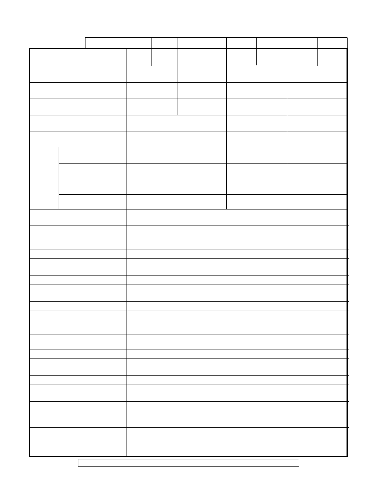
SPECIFICATIONS FOR ALL 50 HZ MODEL
Nominal kW 2.5 3.7 & 4.6 6.3 & 7.5 8.4 12.5 & 12.6 14.9 & 16.7 20.9 22.4
Max. Altitude (ft.) 12,000 8,000 10,000 7,000 10,000 7,000 10,000 7,000
(m) 3,658 2,438 3,048 2,134 3,048 2,134 3,048 2,134
Air Flow @ 70°F (CFM) 400 700 1450 3000
@ 21°C (m3/hr.) 679 1189 2463 5096
Horizontal Air Throw (ft.) 13 25 35 60
(m) 4.0 7.6 10.7 18.2
Max. Mounting Height (ft.) 7 10 10 20
(to underside) (m) 2.1 3.0 3.0 6.1
Motor Power (HP) 1/2 1/2 1/2
(min) (kW) 0.373 0.373 0.373
Fan Diameter (in.) 12 16 20
(mm) 305 406 508
Net without (lbs.) 140 168 201
Weight DS5 (kg) 63.5 76.2 91.2
with (lbs.) 152 180 213
DS5 (kg) 78.9 91.6 96.6
Shipping without (lbs.) 194 218 252
Weight DS5 (kg) 88 98.9 114.3
with (lbs.) 206 230 264
DS5 (kg) 93.4 104.3 119.7
Hazardous Location Rating Class I, Groups C and D; Class II, Groups E, F and G;
Temperature Code T3B [329°F (165°C)]*
Enclosures NEMA Type 7 & 9. For dry, indoor use only. Do not immerse in water. Do not store or use
in areas exposed to rain or snow
Motor Type Explosion-proof. Thermally protected. Permanently lubricated ball bearings.1725 RPM
Fan Aluminum blade. Steel spider and hub with 5/8 in. (15.875 mm) bore
Fan Guard Split design with close wire spacing. 1/4 in. (6.3 mm) dia. probe will not enter
Mounting Holes Four 9/16 in. (14.3 mm) diameter holes at top of heater
Heating Elements Three long-life, low watt-density, high grade metal-sheathed elements
Temperature High-Limit Automatic reset type, snap-action bimetal, open on temperature rise. Rated 100,000
cycles at 10 amps, handles 0.128 amps
Control Circuit 120 Volts, 0.128 amps, 15VA. (Grounded)
Optional Built-in Thermostat Explosion-proof. 36°
Optional Built-in Disconnect Switch DS5 for use only on heaters with total current not exceeding 48-Amps
Lockout handle accepts 1/4” diameter padlock shackle
Optional Three Way Switch Fan only, Off, Auto
Optional Pilot Light Indicates heat-on cycle
Control Transformer Multi-tap primary, 120 V secondary, 50 VA
Contactor 60 or 80 amps. Rated for 1,000,000 mechanical operations. 120 Volts, 15VA coil
(separately fuse-protected)
Heat Transfer Fluid
Cabinet Material 14 ga. (0.075 in.) (1.90 mm) steel. Epoxy coated with five-stage pretreatment, including
iron phosphate. Optional stainless steel
Core Steel with integral aluminum fins, vacuum charged and hermetically sealed
Conduit Material Heavy walled, 0.122 in. (3.1 mm) steel
Overpressure Protection
Operational Temperature Limitations -4°F to 104°F (-20°C to 40°C)
Storage Limitations -49°F to 176°F (-45°C to 80°C), short term to 248°F (120°C). Do not immerse in water
Do not expose to rain or snow.
Long life formulated propylene glycol and water
Preset 100 psig (690 kPa) pressure relief valve, aluminum body, no field serviceable parts
F to 82°F (2°C to 28°C)
*Some units may be Class I, Groups C and D. Please check with factory for clarification
11
Page 12
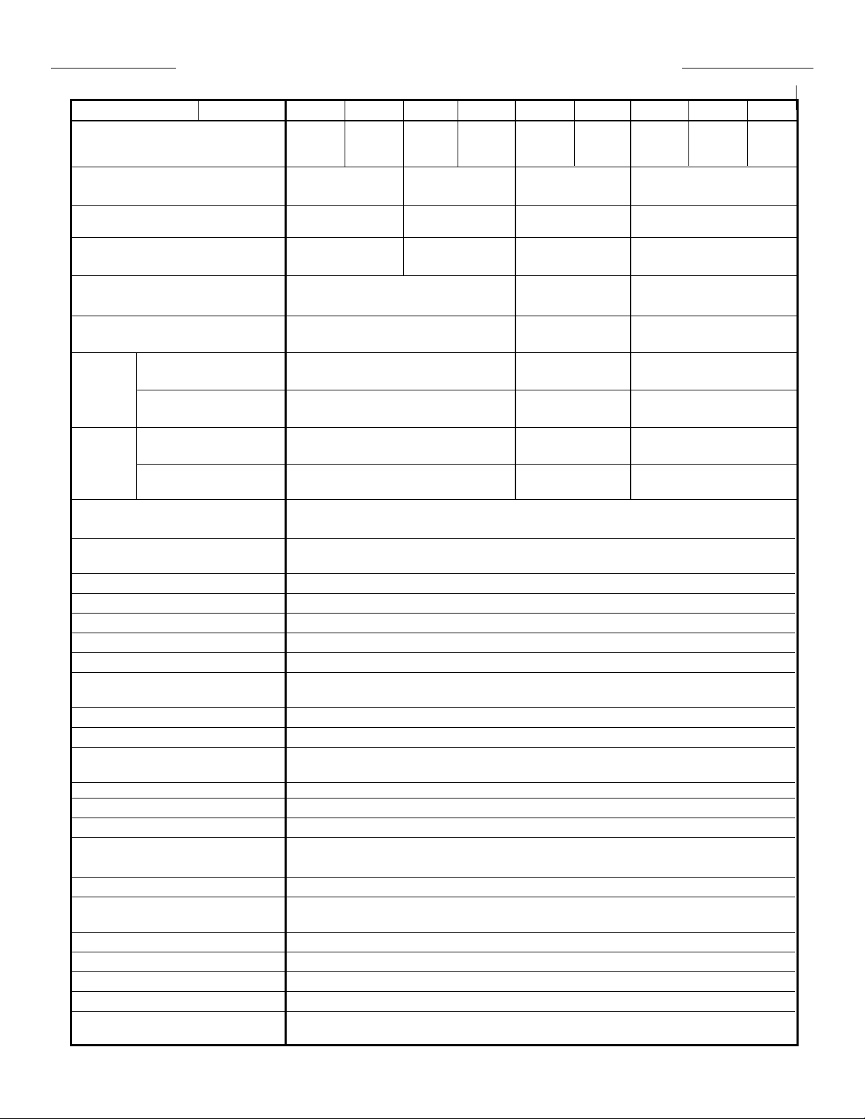
SPECIFICATIONS FOR ALL 60 HZ MODEL
Nominal kW 3 5 7.5 10 15 20 25 30 35
Max. Altitude (ft.) 12,000 8,000 10,000 7,000 10,000 7,000 10,000 7,000 6,000
(m) 3,658 2,438 3,048 2,134 3,048 2,134 3,048 2,134 1,829
Air Flow @ 70°F (CFM) 500 850 1750 3600
@ 21°C (m3/hr.) 850 1444 2973 6116
Horizontal Air Throw (ft.) 15 30 40 70
(m) 4.6 9.1 12.2 21.3
Max. Mounting Height (ft.) 7 10 10 20
(to underside) (m) 2.1 3.0 3.0 6.1
Motor Power (HP) 1/2 1/2 1/2
(min) (kW) 0.373 0.373 0.373
Fan Diameter (in.) 12 16 20
(mm) 305 406 508
Net without (lbs.) 140 168 201
Weight DS5 (kg) 63.5 76.2 91.2
with (lbs.) 152 180 213
DS5 (kg) 78.9 81.6 96.6
Shipping without (lbs.) 194 218 252
Weight DS5 (kg) 88 98.9 114.3
with (lbs.) 206 230 264
DS5 (kg) 93.4 104.3 119.7
Hazardous Location Rating Class I, Groups C and D; Class II, Groups E, F and G;
Temperature Code T3B [329°F (165°C)]
Enclosures NEMA Type 7 & 9. For dry, indoor use only. Do not immerse in water. Do not store or use
in areas exposed to rain or snow
Motor Type Explosion-proof. Thermally protected. Permanently lubricated ball bearings. 1725 RPM
Fan Aluminum blade. Steel spider and hub with 5/8 in. (15.875 mm) bore
Fan Guard Split design with close wire spacing. 1/4 in. (6.3 mm) dia. probe will not enter
Mounting Holes Four 9/16 in. (14.3 mm) diameter holes at top of heater
Heating Elements Three long-life, low watt-density, high grade metal-sheathed elements
Temperature High-Limit Automatic reset type, snap-action bimetal, open on temperature rise. Rated 100,000 cycles
at 10 amps, handles 0.128 amps
Control Circuit 120 Volts, 0.128 amps, 15VA. (Grounded)
Optional Built-in Thermostat Explosion-proof. 36°
Optional Built-in Disconnect Switch DS5 for use only on heaters with total current not exceeding 48-Amps.
Lockout handle accepts 1/4” diameter padlock shackle
Optional Three Way Switch Fan only, Off, Auto
Optional Pilot Light Indicates heat-on cycle
Control Transformer Multi-tap primary, 120 V secondary, 50 VA
Contactor 60 or 80 amp. Rated for 1,000,000 mechanical operations. 120 Volts, 15VA coil
(separately fuse-protected)
Heat Transfer Fluid
Cabinet Material 14 ga. (0.075 in.) (1.90 mm) steel. Epoxy coated with five-stage pretreatment, including iron
phosphate. Optional stainless steel
Core Steel with integral aluminum fins, vacuum charged and hermetically sealed
Conduit Material Heavy walled, 0.122 in. (3.1 mm) steel
Overpressure Protection
Operational Temperature Limitations -4°F to 104°F (-20°C to 40°C)
Storage Limitations -49°F to 176°F (-45°C to 80°C), short term to 248°F (120°C). Do not immerse in water
Do not expose to rain or snow
Long life formulated propylene glycol and water
Preset 100 psig (690 kPa) pressure relief valve, aluminum body, no field serviceable parts
12
F to 82°F (2°C to 28°C)
Page 13
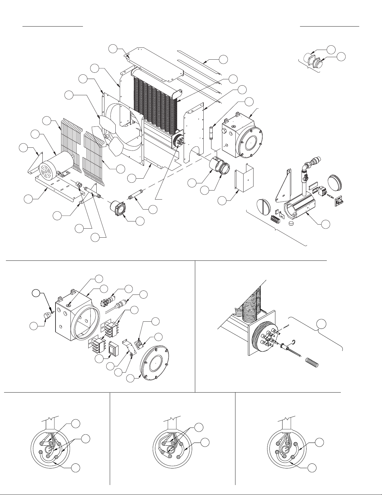
HEATER ASSEMBLY DIAGRAM
11
12
10
5
4
6
7
1
Optional Built-in
thermostat replaces
item #16
22
23
3
8
18
See
control enclosure
9
assembly diagram
(below)
9
2
See high-limit
assembly diagram
(below)
17
19
20
21
13
14
15
16
Optional
built-in
disconnect
switch kit
41
CONTROL ENCLOSURE
ASSEMBLY DIAGRAM
35
34
BUS-BAR CONFIGURATION
ALL 1-PHASE MODELS
38
39
36
26
24
27
33
32
25
29
30
28
31
BUS-BAR CONFIGURATION
FOR ALL 3-PHASE
(EXCEPT 380 50 HERTZ & 400 50 HERTZ)
38
39
HIGH LIMIT
ASSEMBLY DIAGRAM
37
BUS-BAR CONFIGURATION
FOR ALL 3-PHASE 380 V & 400 V 50 HERTZ MODELS
39
40
40
13
Page 14
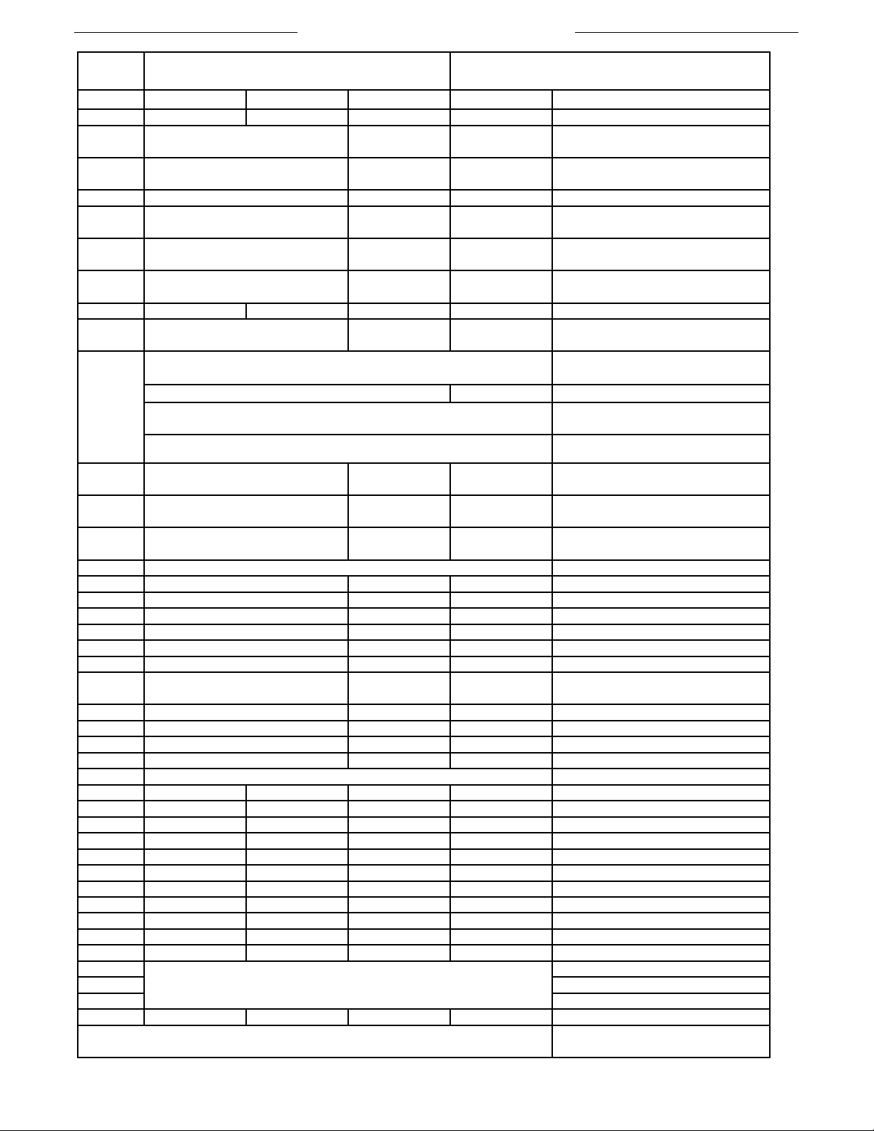
PARTS LIST
FORCED AIR ELECTRIC HEATERS
PART NUMBERS
ITEM 2.5 - 4.6 kW 6.3 - 10 kW 12.5 - 20 kW 20.9 - 35 kW Description
1 ** ** ** ** Core
2
3
4 4075 4076 4077 Louver Kit, c/w screws
5
6
7
8 4022 4023 4024 4025 Fan Blade
9
10
11
12
13
14 3737 (Emerson Motors) 4590 ( Baldor & Marathon Motors) Coupling, Motor
15 9500 3813 10389 Conduit, Motor
16 5371 5371 5371 Cover, Thermostat Enclosure
17 3813 3813 3813 Conduit, Control Enclosure
18 9314 9315 9316 Conduit, Element Enclosure
19 9679 9679 9679 Enclosure, Element
20 3510 3510 3510 Cover, Element Enclosure
21
22 4983 4983 4983 Enclosure, Thermostat
23 5032 5032 5032 Thermostat, Built-in-kit
24 - - - Enclosure, Control
25 ** ** ** Contactor
26 10556 (60HZ) 11295 (50HZ) Transformer
27 3809 3809 3809 3809 Bracket, Printed Circuit Board
28 1876 1876 1876 1876 Terminal, 6-14 Ga. Screw Lug
29 9357 9357 9357 9357 Fuse, Buss MDQ - 1/2 Amp
30 3514 3514 3514 3514 Assembly, Printed Circuit Board
31 9158 9158 9158 9158 Cover, Control Enclosure
32 9279 9279 9279 9279 Bulb, Pilot Light
33 9775 9775 9775 9775 Switch, Explosion Proof 3-Way
34 9267 9267 9267 9267 Thermowell, Ambient High-Limit
35 - - - - High Limit, Ambient Temperature
36 9289 9289 9289 9289 Plug, 1" NPT Explosion Proof
37 - - - - Temperature High-Limit Kit
38
39 Bus-Bar, Small Curved
40 Bus-Bar, Large Curved
41 - - - - Kit, DS5 Assembly
**See technical data table for part numbers. NOTE: For items not shown,
please contact factory.
Painted: 9203
S.S.: 9507
Painted: 9191
S.S.: 9192
Painted: 9200
S.S.: 9513
Painted: 9197
S.S.: 9510
Painted: 3782
S.S.: 9212
Painted: 4078
S.S.: 9504
1979 (Emerson) 10388 (Marathon)
9896 (Baldor) N/A 480V 1PH 60HZ
1699 (Emerson) 10387 (Marathon)
2433 (Emerson) 10672 (Marathon) 600V 3PH 60HZ
Painted: 3789
S.S.: 9112
Painted: 3785
S.S.: 9206
Painted: 3788
S.S.: 9111
Painted: 9354
S.S.: 9516
Provided with Core Kits**
Painted: 9204
S.S.: 9508
Painted: 9193
S.S.: 9194
Painted: 9201
S.S.: 9514
Painted: 9198
S.S.: 9511
Painted: 3783
S.S.: 9213
Painted: 4079
S.S.: 9505
Painted: 3789
S.S.: 9112
Painted: 3786
S.S.: 9207
Painted: 3788
S.S.: 9111
Painted: 9355
S.S.: 9517
14
Please have model and serial number available
before calling
Painted: 9205
S.S.: 9509
Painted: 9195
S.S.: 9196
Painted: 9202
S.S.: 9515
Painted: 9199
S.S.: 9512
Painted: 3784
S.S.:9214
Painted: 4080
S.S.: 9506
Painted: 3789
S.S.: 9112
Painted: 3787
S.S.: 9208
Painted: 3788
S.S.: 9111
Painted: 9356
S.S.: 9518
Panel, Bottom
Panel, Left Side
Panel, Top
Panel, Right
Panel, Fan Shroud
Fan Guard Kit
208/240V 1PH 60HZ
220V 1PH 50HZ
208/240/480V 3PH 60HZ
380/415V 3PH 50HZ
Bracket, Motor Mount Right
Channel, Motor Mount
Bracket, Motor Mount Left
Panel, Element Enclosure Guard
Bus-Bar, Straight
Page 15
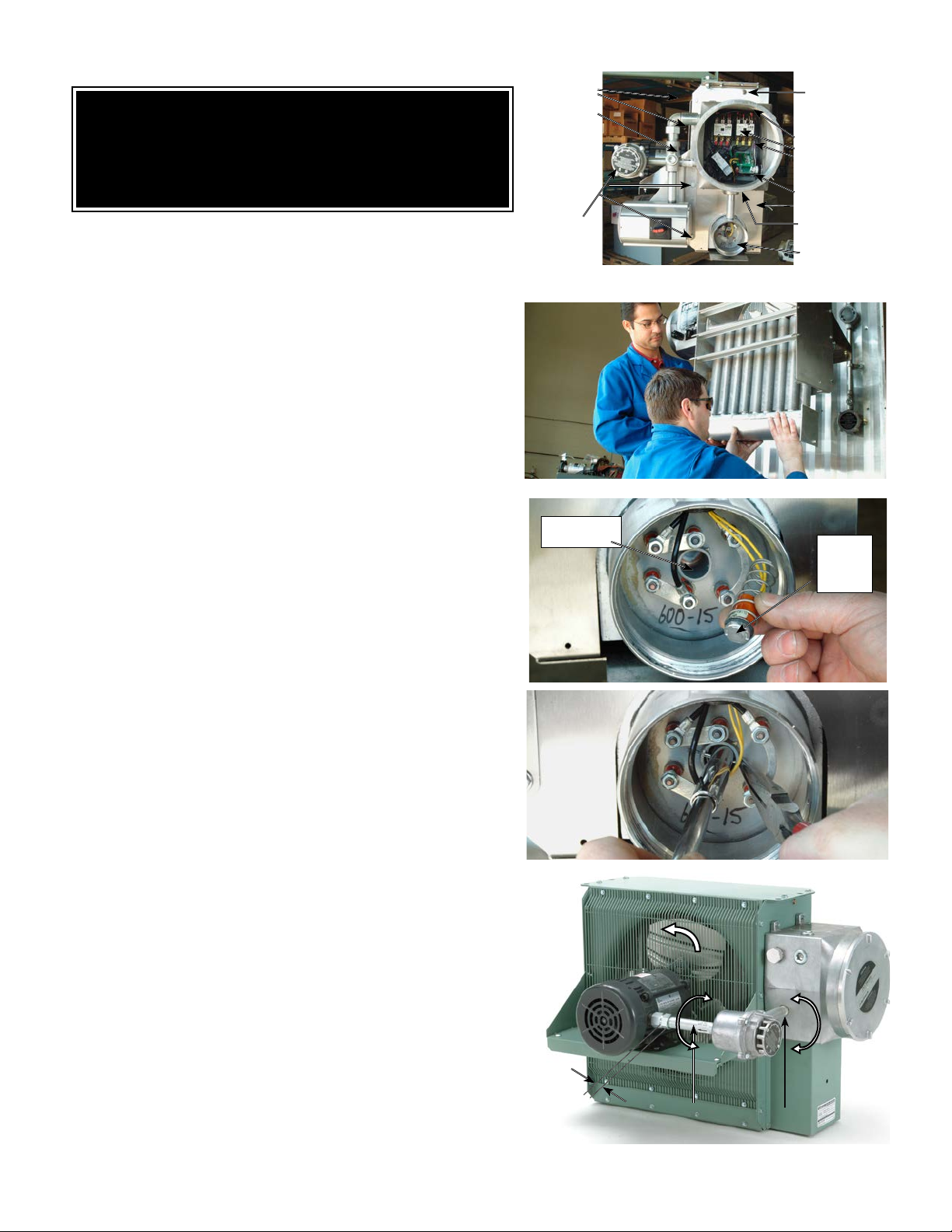
REPAIR & REPLACEMENT
WARNING
Disconnect heater from power supply at integral disconnect or fuse box before
opening enclosures or servicing heater. Lock the switch in the “OFF” (open)
position and/or tag the switch to prevent unexpected power application.
IF INTEGRAL DISCONNECT IS BEING SERVICED, verify that power has
been disconnected at fuse box or main panel. Lock the switch in the “OFF”
(open) position and/or tag the switch to prevent unexpected power application.
Heater surfaces may be hot.
1. After repairing any component:
a. check that electrical connections are correct and secure (see Figure 9),
b. remove any foreign material from enclosures,
c. install and secure all covers,
d. ensure that all fasteners are tight,
e. remove all foreign objects from heater, and
f. ensure air exits through louvers and fan rotates counterclockwise when
viewed from rear of heater (see Figure 14).
CORE
The heater core is vacuum charged and not field repairable.
For core removal:
1. Remove cabinet bottom and element enclosure cover.
2. Disconnect all wires entering element enclosure (see Figure 10).
3. Slightly loosen all cabinet bolts shown in Figure 10, to prevent the core
from binding.
4. With an assistant supporting the weight of the core, remove the 3 core
mounting bolts. Carefully lower the core out of the cabinet
(see Figure 11).
5. To return core to factory, use crate supplied with exchange core
to protect
the element terminals and plate threads.
6. To reinstall, lift the core up into cabinet while an assistant guides the
element wires into the element enclosure conduit.
7. Position the core and tighten the 3 core mounting bolts. Tighten the
remaining cabinet bolts.
Loosen
bolts
only,
do not
remove.
Conduit
Junction
Enclosure
{
Thermowell
Remove this
core mounting
bolt & two
others on the
opposite side.
Loosen
bolts
only,
do not
}
remove.
Control
Enclosure
Element
Enclosure
FIGURE 10
FIGURE 11
3/32”
(2mm)
Drop
TEMPERATURE HIGH-LIMIT
1. Remove temperature high-limit assembly and clean the inside of the
thermowell (see Figure 12). A clean thermowell will ensure good
thermal contact.
2. Use only a factory supplied temperature high-limit to ensure safe operation.
(refer to the instructions that accompany the replacement Temperature High-
Limit Kit).
3. Reinstall the temperature high-limit assembly with the snap ring and spring
into the thermowell without damaging the insulating tube. Secure in place
with the cotter pin (see Figure 13).
MOTOR, FAN & FAN GUARD
1. Remove bolts holding the motor to the motor mount. On units with a built
in thermostat, remove the bolts on the back of the thermostat enclosure.
2. Remove conduit #1 located between motor junction box and con trol
en closu re b y turni ng i t in the direction illustrated (see Figure 14).
Note conduits #1
one end, this end is indicated by a machined groove.
3. Remove the 2 piece fan guard assembly (see Figure 15).
4. Lift the motor assembly off the motor mount.
5. Before removing the fan, measure and record the location of the fan hub on the
motor shaft (see Figure 16). If difficult to remove, use a gear puller on the fan hub.
6. To reassemble, place motor assembly onto motor mount and fasten the fan guard
to cabinet.
7. Simultaneously engage and tighten both ends of conduit #1 into enclosures.
Leave a 1/16” to 3/16” (1.6 to 4.8 mm) gap between the motor and fan guard
(see Figure 16). Adjust conduit #2 to center the fan in the shroud.
8. To ensure a minimum 5 thread engagement, threaded ends of conduits must
protrude a minimum of 1/16” (1.6mm) into enclosures. The groove on conduit #2
must not be more than 7/8” (22mm) from motor coupling (see Figure 14).
9. Bolt motor to motor mount. Manually spin the fan blade to ensure fan rotates freely.
10. Air must exit through louvers and fan must rotate counterclockwise when viewed
from rear of heater (see Figure 14).
and #2 are not interchangeable and have left hand threads on
7/8” (22mm)
(From groove to
face of coupling)
Air inlet
Rotation
Remove
Install
Conduit #2 Conduit #1
FIGURE 12
FIGURE 13
Install
Remove
FIGURE 14
15
Page 16
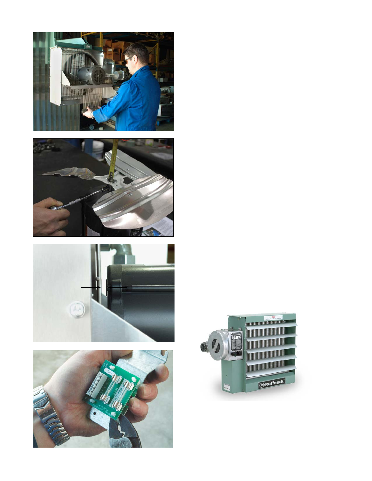
FIGURE 15
PRINTED CIRCUIT BOARD
1. After removing the printed circuit board (P.C. Board) bracket assembly
from the control enclosure, separate the P.C. Board from the bracket
by cutting off the plastic spacers (see Figure 18).
2. Reinstall a new factory supplied P.C. Board onto the mounting bracket
using new non-conducting spacers of the same length. Spacers are
supplied with a new P.C. Board. Reinstall the control circuit ground
wire to the printed circuit board bracket (see Figure 9).
CONTACTOR
1. Loosen, but do not remove contactor mounting screws. Slide
contactor off mounting screws.
2. Replace with a factory supplied contactor of the same rating.
TRANSFORMER
1. Replace with a factory supplied transformer of the same rating.
2. On the new transformer, select primary wires to match heater voltage.
Ensure that the correct transformer secondary lead is grounded (see
Figure 9). Individually terminate all unused wires using closed
end connectors.
FUSE
Replace fuse with one of the same type and rating as indicated on P.C.
Board or refer to parts list. An extra fuse should be stored in the clips
marked “SPARE”.
HEATING ELEMENTS
Heating elements are an integral part of the vacuum charged core. A factory
exchange core can be shipped immediately from stock. Refer to “Core”
section for details.
1/16” to 3/16”
(1.6 to 4.8mm)
CABINET PANELS
Bolt-on cabinet panels are individually replaceable.
FIGURE 16
FIGURE 17
16
FIGURE 18
Page 17

NOTES
Page 18

NOTES
Page 19

NOTES
Page 20
5918 Roper Road, Edmonton, Alberta, Canada T6B 3E1
Phone: (780) 466-3178 Fax: (780) 468-5904
PLEASE ADHERE TO INSTRUCTIONS PUBLISHED IN THIS MANUAL.
Failure to do so may be dangerous and may void certain provisions of your warranty.
For further assistance, please call:
24 Hr. Hotline: 1-800-661-8529
(U.S.A. and Canada)
Please have model and serial numbers available before calling.
WARRANTY: Under normal use the Company
warrants to the purchaser that defects in material or
workmanship will be repaired or replaced
without charge for a period of 36 months from date of
shipment. Any claim for warranty must be reported to
authorized repair or replacement within the terms of
this warranty.
Subject to State or Provincial law to the contrary, the
Company will not be responsible for any expense for
installation, removal from service, transportation, or
damages of any type whatsoever, including damages
arising from lack of use, business interruptions, or
incidental or consequential damages.
The Company cannot anticipate or control the
conditions of product usage and therefore
accepts no responsibility for the safe application and
suitability of its products when used alone or in
combination with other products. Tests for the safe
application and suitability of the products are the sole
responsibility of the user.
This warranty will be void if, in the judgment of the
Company, the damage, failure or defect is the result of:
• vibration, radiation, erosion, corrosion, process
contamination, abnormal process conditions,
temperature and pressures, unusual surges or
pulsation, fouling, ordinary wear and tear, lack of
maintenance, incorrectly applied utilities such as
voltage, air, gas, water, and others or any
combination of the aforementioned causes not
• any act or omission by the Purchaser, its agents,
servants or independent contractors which for
greater certainty, but not so as to limit the generality
of the foregoing, includes physical, chemical or
mechanical abuse, accident, improper
installation of the product, improper storage and
handling of the product, improper application or the
misalignment of parts.
manufacturing defects apparent within 30 days from
the date of installation.
The Company neither assumes nor
authorizes any person to assume for it any other
obligation or liability in connection with the product(s).
The Purchaser agrees that all warranty work required
after the initial commissioning of the product will be
provided only if the Company has been paid by the
Purchaser in full accordance with the terms and
conditions of the contract.
The Purchaser agrees that the Company makes
no warranty or guarantee, express, implied or
statutory, (INCLUDING ANY WARRANTY OF
MERCHANTABILITY OR WARRANTY OF FITNESS
FOR A PARTICULAR PURPOSE) written or oral, of
the Article or incidental labour, except as is expressed
or contained in the agreement herein.
LIABILITY: Technical data contained in the catalog or
on the website is subject to change without notice. The
Company reserves the right to make dimensional and
other design changes as required. The Purchaser
acknowledges the Company shall not be obligated
to modify those articles manufactured before the
formulation of the changes in design or improvements
of the products by the Company.
The Company shall not be liable to compensate or
indemnify the Purchaser, end user or any other party
against any actions, claims, liabilities, injury, loss, loss
of use, loss of business, damages, indirect or conse-
es (including legal expenses), costs, obligations and
causes of action of any kind arising wholly or partly
from negligence or omission of the user or the misuse, incorrect application, unsafe application, incorrect storage and handling, incorrect installation, lack
of maintenance, improper maintenance or improper
operation of products furnished by the Company.
Edmonton
1-800-661-8529
(780) 466-3178
F 780-468-5904
Oakville
1-800-410-3131
(905) 829-4422
F 905-829-4430
Orillia
1-877-325-3473
(705) 325-3473
F 705-325-2106
Greensburg
1-800-473-2402
(812) 663-4141
F 812-663-4202
Houston
1-855-219-2101
(281) 506-2310
F 281-506-2316
Denver
1-855-244-3128
(303) 979-7339
F 303-979-7350
 Loading...