


OWNER’S MANUAL
CR1 Triton
TM
Series
Corrosion-Resistant Washdown Unit Heaters
RuffneckTMis a registered tradesmark and TritonTMis a trademark of
CCI Thermal Technolgoies inc..
Copyright © 2003. All rights reserved.
WARNING!
READ ALL IMPORTANT NOTICES ON PAGE 2.
PLEASE ADHERE TO INSTRUCTIONS PUBLISHED IN THIS MANUAL.
Failure to do so may be dangerous and may void certain provisions of your warranty.
Printed in Canada
– 1 –
This manual covers installation, maintenance, repair and replacement parts.
Model Coding
BUILT-IN CONTROL OPTIONS
T- Built-in room thermostat
P- Built-in pilot light
F - Built-in 3-position fan
switch (on, off, fan only)
D - Built-in door interlocking
disconnect switch
M - Built-in manual reset
temperature high-limit
E - Monel elements
HERTZ
60
PHASE
1
3
VOLTAGE
208
240
480
600
1
st
GENERATION
MODEL SERIES
CR1
480
1
60
TPFDME
20
Pt. No. 7516-1
3
KILOWATTS
3
5
7.5
10
15
20
25
30
35
39

1. Read and follow all instructions in this manual.
2. Heater is not to be used in hazardous atmospheres where
flammable vapors, gases, liquids or other combustible
atmospheres are present.
3. Heater is to be connected and serviced only by a
qualified electrician.
4. Installation and wiring of the heater must adhere to all
applicable codes.
5. Before opening any enclosures, disconnect the heater
from the power supply. Lock the switch in the “OFF”
position and/or tag the switch to prevent unexpected
power application.
6. The heater is not to be operated with the high-limit
disconnected from the control circuit.
7. The heater is not to be operated if the bulb or capillary
of the high-limit is damaged.
8. Do not operate the heater in atmosphere corrosive to
type 304 stainless steel.
9. Elements get hot during operation. Contact can cause
burns.
10. Use factory replacement parts only.
11.Maximum ambient operating temperature is 40°C
(104°F).
12. Type 4X conduits must be used for field connection in
order to maintain watertightness of the enclosure.
13. Do not operate the heater with the louvers deformed
from their factory preset positions.
14. Wash with water pressure less than 70 psi.
15. Complies with U.S. Coast Guard regulations only when
indicated on heater data plate and when the discharge
grill directs airflow downward.
16. If there are any questions or concerns regarding the
heater, please refer to contact info on page 10.
WARNING:
Disconnect heater from the power supply before opening enclosures, washing or servicing heater.
Lock the switch in the “OFF” (open) position and/or tag the switch to prevent unexpected power application.
This heater should only be serviced by qualified personnel with electrical heating equipment experience.
– 2 –
HEA
TER MAINTENANCE CHECKLIST
Heater Model: ____________________________ Serial No.: ______________________________
Date of Maintenance: ______________________ Maintenance Done By: ____________________
Comments: ________________________________________________________________________
________________________________________________________________________
PERIODIC (before and as required during heating season)
ANNUAL (before heating season)
IMPOR
TANT NOTICES
WARNING:
Read and adhere to the following. Failure to do so may result in severe or fatal injury.
2. MECHANICAL
❑ Check for leakage inside the control enclosure. The
electrical enclosure should be dry inside.
❑ Check enclosure seal. Seal should be free of nicks and
cuts.
❑ Check motor shaft bearing play. Replace motor if play
is excessive, or if motor does not run quietly and
smoothly. Bearings are permanently lubricated.
❑ Check fan. Replace immediately if cracked or
damaged.
❑ Check high-limit bulb and capillary. Replace
immediately if damaged.
❑ Check tightness of all hardware. All fasteners must be
tight.
❑ Turn heater on for a minimum of five minutes. Check
for warm air exiting heater through discharge grill.
1. CLEAN (Use water pressure less than 70 psi)
❑ Finned Elements ❑ Motor ❑ Fan
❑ Discharge Grill ❑ Inlet Grill
2. CHECK
❑ All watertight seals for condition and tightness
❑ Motor for smooth, quiet operation
1. ELECTRICAL
❑ Check all terminal connections and conductors.
Tighten loose connections. Conductors with
damaged insulation must be replaced.
❑ Inspect contactor contacts. If badly pitted,
burned or welded shut, replace with factorysupplied contactor.
❑ Check all watertight fittings. Replace damaged
seals with factory supplied seals.
❑ Check electrical resistance on all load side legs.
Reading should be balanced (±5%).
Photocopy
this page
for reuse.

INSTALLATION
The installation instructions provide a general guideline for the installation and wiring of the heater.
All applicable codes must be adhered to.
MECHANICAL
– 3 –
Minimum clearances for
service and airflow:
Front - 72" (1829 mm)
Back - 6" (152 mm)
Right Side - 10" (254 mm)
Left Side - 1" (25 mm)
Top - 8" (203 mm)
Bottom - 72" (1829 mm)
Heater can be mounted
up to a 45° angle.
Using factory-supplied mounting bracket (included with each heater).
Customer-supplied bracket
DIM. A B C D E F
3 to 10kW
12.5" (318 mm) 12.8" (325 mm) 8.5" (216 mm) 24.4" (620 mm) 6.4" (162.5 mm) 0.9" (23 mm)
15 and 20kW
12.1" (307 mm) 16.7" (425 mm) 7.5" (190 mm) 23.4" (595 mm) 8.4" (212.5 mm) 1.2" (30 mm)
25 to 39 kW
12.1" (307 mm) 20.7" (525 mm) 7.5" (190 mm) 23.4" (595 mm) 10.3" (262.5 mm) 1.3" (32 mm)
Figure 1
Figure 3
Figure 2
Heaters must be installed as follows:
LOCATION
1. The heater’s inlet and discharge areas must not be
obstructed. See figure 1 for minimum clearances.
2. The air discharge is not to be directed at a
thermostat.
3. The air discharge is directed across areas of heat
loss, such as windows.
4. The air discharge is directed along and at a slight
angle toward exterior walls.
5. If equipment freeze protection is important, locate
the heater as close to the equipment as possible
while maintaining minimum clearances.
MOUNTING
(see figures 2 and 3)
1. The heater must be permanently mounted with the
control box at the bottom.
2. The mounting surface must be strong enough to:
a.) support the heater’s weight,
b.) provide sufficient stiffness to prevent excessive
vibration, and
c.) withstand abusive situations such as transportable
installations of the heater.wiring of the heater must
3. Install the heater at least 6 ft. (1.8 m) from the floor.
4. Louvered discharge grill can be rotated in 45°
increments.
Heater only complies with U.S. Coast
Guard regulations when the grill is installed such that
the airflow is directed downward.
5. For maximum tilt angles, see figure 3. For maximum
mounting height, see general specifications table on
page 9.
(3 to 20kW
units only)
B dia.
E
DISCHARGE
GRILL
1/2" UNC
MOUNTING
HOLE
D
A
F
POWER SUPPLY
CONNECTION
2"
(51 mm)
3.8"
(97 mm)
C
8.9"
11.3"
(227 mm)
(287 mm)
2.3"
OPTIONAL DOOR INTERLOCKING
DISCONNECT SWITCH
CEILING MOUNT
14.6"
(370 mm)
WALL MOUNT
(59 mm)
7.5"
(190 mm)
(329 mm)
13"
45° MAX
AIRFLOW

ELECTRICAL
WARNING
Disconnect the power supply before installation of the heater. Lock the switch in
the “OFF” (open) position and/or tag the switch to prevent unexpected power application.
Installation and wiring of the heater must adhere to all applicable codes.
Single phase without
3-position switch
Single phase with
3-position switch
– 4 –
Figure 7
Figure 8
Figure 5
Figure 6
GENERAL
1. Use only copper conductors and approved Type 4X wiring
methods during installation. Refer to the “Technical Data” table
for the voltage, amperage and wattage ratings when sizing for the
appropriate conductors.
2. Supply voltage is to be within 10% of the data plate voltage.
3. External over-current protection is required and must meet data
plate ratings for voltage, amperage and frequency.
FIELD WIRING
1. Heater is supplied with an enclosure that has 2 standard
3/4" trade size conduit openings to accommodate the line conductors or
external thermostat connection.
2. Heater may be supplied with a factory-installed built-in room thermostat.
On heaters not supplied with this option, a remote thermostat is required.
Connect the remote thermostat conductors to the terminal block marked
T1, T2 and Ground. Any thermostat used with this heater must be:
a) Listed or Approved
b) Type 4X rated*, and
c) Rated at 120 volt minimum and 5 amp minimum.
*An appropriate Type 4X rated room thermostat is available from
the factory.
FINAL INSPECTION
1. Before application of electrical power:
a) check that all connections are secured and comply with the applicable
code requirements,
b) confirm that the supply voltage is compatible with the data
plate specifications,
c) remove any foreign objects from the heater,
d) ensure all external fittings and enclosure covers are secured,
e) ensure that the fan rotates freely, and
f) if equipped, ensure manual reset high-limit has been reset.
Figure 4
Three phase with
3-position switch
208, 240, 480 volt three phase models
without 3-position switch
Three phase without
3-position switch
600 volt models
FIELD CONNECTIONS
OPTIONAL
DISCONNECT
SWITCH
FIELD CONNECTIONS
OPTIONAL
DISCONNECT
SWITCH
L1
ELEMENTS
MOTOR
L1
CONTACTOR
MOTOR
L2
CONTACTOR
MOTOR
CONTACTOR
L2
G
G
ELEMENT
CONTACTOR
ELEMENTS
MOTOR
G
TRANSFORMER
G
ELEMENT
REDUNDANT
CONTACTOR
120V
OPTIONAL
PILOT
LIGHT
AUTO RESET
HIGH-LIMIT
3 POSITION SWITCH
ON OFF
FAN ONLY
B
120V
OPTIONAL
PILOT
LIGHT
A & C
A
A
B
B
C
C
TRANSFORMER
REDUNDANT
CONTACTOR
(MANUAL RESET
OPTIONAL)
T1
T2
ROOM
THERMOSTAT
2
3
NO
NC
FAN DELAY
1
TEMPERATURE
HIGH-LIMIT
T1
T2
THERMOSTAT
2
3
NC
NO
FAN DELAY
1
ROOM
FIELD CONNECTIONS
OPTIONAL
DISCONNECT
SWITCH
L1
L2 L3
G
TRANSFORMER
120V
G
ELEMENT
CONTACTOR
OPTIONAL
REDUNDANT
CONTACTOR
ELEMENTS
MOTOR
CONTACTOR
MOTOR
3 POSITION SWITCH
ON OFF
A & C
PILOT
LIGHT
FIELD CONNECTIONS
L2
L1
FAN ONLY
B
TEMPERATURE
HIGH-LIMIT
A
A
B
B
C
C
T1
T2
ROOM
THERMOSTAT
3
2
NO
NC
FAN DELAY
1
FIELD CONNECTIONS
OPTIONAL
DISCONNECT
SWITCH
MOTOR
L1
L2 L3
G
G
ELEMENT
CONTACTOR
ELEMENTS
TRANSFORMER
120V
OPTIONAL
PILOT
LIGHT
REDUNDANT
CONTACTOR
TEMPERATURE
HIGH-LIMIT
NO
1
T1
T2
ROOM
THERMOSTAT
2
3
NC
FAN DELAY
OPTIONAL
DISCONNECT
SWITCH
G
TRANSFORMER
G
120V
ELEMENT
CONTACTOR
OPTIONAL
PILOT
LIGHT
REDUNDANT
CONTACTOR
ELEMENTS
MOTOR
TEMPERATURE
HIGH-LIMIT
2
NO
1
T1
T2
ROOM
THERMOSTAT
3
NC
FAN DELAY

REPAIR AND REPLACEMENT
WARNING
Disconnect heater from the power supply before opening enclosures or servicing heater. Lock the switch in the
“OFF” (open) position and/or tag the switch to prevent unexpected power application. This heater should
only be serviced by qualified personnel with electrical heating equipment experience.
Note: ONLY USE FACTORY SUPPLIED REPLACEMENT PARTS OF THE SAME SPECIFICATION.
HEATING ELEMENTS
1. Disconnect all wires connected to the element terminals and remove all bus
bars. Remove discharge grill from heater. If equipped, remove element
brackets from heater.
2. Remove elements, noting their proper placement.
3. Install factory-supplied replacement elements such that the smallest loop of
the spiral element is closest to the discharge end of the heater (see figure 9).
Ensure that the element gaskets are in place and in good condition.
Tighten the element bushing nuts until the gaskets are snug between the
bushing shoulders and enclosure. Compress the gaskets by turning the nuts
1 to 1
1
/4 additional turns. Check that the elements are not in contact with
the cabinet or each other.
4. Reinstall all bus bars, wires, brackets, and discharge grill.
FAN
1. Remove inlet grill from heater. Remove the three screws securing the fan
to the fan hub attached to the motor.
2. Replace fan with factory-supplied fan. Install the fan such that the “spider”
of the fan (see figure 10) faces the outside of the heater (i.e., facing away
from the motor). The spider should be visible from the rear of the heater
(as shown in figure 10).
GENERAL
1. To operate heater, make sure power supply is
properly connected as specified in the wiring
schematic (see figure 4 to 8 on page 4).
2. Ensure that the thermostat controlling the heater is
set above the ambient temperature.
3. If the heater is provided with the optional door
interlocking disconnect switch, ensure the switch is
in the “ON” position.
4. If the heater is provided with the optional 3-position
fan switch, ensure the switch is in the “ON” position.
Note: If the switch is in the “FAN ONLY” position,
only the fan will energize, not the elements.
5. If the heater is provided with the optional pilot light,
the light will illuminate only when the elements are
energized.
6. The heater is provided with a fan delay relay. The
fan will energize approximately 20 seconds after the
elements are energized. The fan will remain in
operation for approximately 2 minutes after the
thermostat de-energizes the elements. If the 3position fan switch is turned to the “OFF” position,
the fan will de-energize immediately.
7. During normal operation, the high-limit control
should not cycle the heater ON and OFF. If cycling
occurs, check to see if there is an airflow blockage.
If there are no obstructions, the heater must be
examined by qualified personnel to determine the
cause of the high-limit cycling.
8. The heater can be washed down with water at
pressures less than 70 psi.
OPERATION
Figure 9
Figure 10
– 5 –
SMALL LOOP OF
SPIRAL ELEMENT
AIR FLOW
FAN SPIDER
VIEW FROM
INLET END
OF HEATER

10
7
3
12
15
14
13
8
5
4
11
9
2
WALL MOUNT
BRACKET DETAIL
217.0
126
126.0
152
2
2
1
19
6
22
21
17
20
26
20
23
25
PARTS DIAGRAM
TEMPERATURE HIGH-LIMIT
1. Remove discharge grill from heater. Remove clips
securing bulb and capillary to cabinet.
2. Inside electrical enclosure, remove lock nut from
high-limit compression fitting and remove fitting from
enclosure.
3. Remove compression nut from the fitting (see Figure
11). Remove seal from fitting. Remove fitting from
capillary.
4. Remove high-limit switch from the enclosure.
5. Replace high-limit with factory-supplied replacement
high-limit.
6. Reinstall high-limit switch to bracket in the control
enclosure.
7. Slip capillary sleeve over capillary.
Note: For 25 to 39 kW heaters, the sleeve must be cut
to 8.25 in. (210 mm). For 15 and 20 kW heaters, the
sleeve must be cut to 14.125 in. (360 mm). For 3 to
10 kW heaters, sleeve does not have to be cut to
length.
8. Slide lock nut over bulb and capillary. Insert bulb and
capillary through the enclosure opening.
9. Place compression fitting body over capillary. Install
seal on capillary and insert seal into body of fitting
(see Figure 11).
10. Loosely install top nut onto compression seal body.
Secure fitting to enclosure with lock nut on the inside
of the enclosure. Tighten lock nut to ensure watertight
seal.
11. Reinstall the bulb and capillary using the original
clips. Ensure the bulb is in the same position as the
previous high-limit. The bulb tip should be 3.94 in.
(100 mm) from the discharge edge of the cabinet.
12. Tighten top nut on compression seal.
– 6 –
Figure 11
Figure 12
BULB
CAPILLARY
NUT
SEAL
COMPRESSION
CABINET
FITTING BODY
O-RING
LOCKNUT
SLEEVE

– 7 –
Item# Description 3kW 5kW 7.5kW 10kW 15kW 20kW 25kW 30kW 35kW 39kW
208 V Stainless Steel 8365 7747 7752 7758 7761 - - - - -
Monel 8382 8109 8112 8115 8118 - - - - -
240 V Stainless Steel 8366 7748 7753 7759 7762 - - - - -
1 Elements Monel 8383 8110 8113 8116 8119 - - - - -
480 V Stainless Steel 8367 7751 7756 7760 7763 7764 8357 8358 8359 8360
Monel 8384 8111 8114 8117 8120 8121 8374 8375 8376 8377
600 V Stainless Steel 8368 8369 8370 8371 8372 8373 8361 8362 8363 8364
Monel 8385 8386 8387 8388 8389 8390 8378 8379 8380 8381
2 Inlet Grill 7485 7484 8251
3 Discharge Grill 7487 7486 8252
4 Fan Blade 7522 7523 8304
5 Fan Hub 7519
6 High-Limit Kit Auto Reset 7740
Manual Reset 7741
7 Element Bracket N/R 7589
8 Motor Kit 208-480 V 7742
600 V 8302
9 Attachment Bracket 7490
10 High-Limit Clip 7656
11 Mounting Bracket 7501
12 Element Gasket 7579
13 Built-in Thermostat Kit 7743
14 Pilot Light Kit 7744
15 3-Position Fan Switch 7745
16 Disconnect Switch Kit 7746
17 Tr ansformer 208-480 V 7478
600 V 8260
18 Motor Capacitor 7502
19 Fan Delay Relay 7470
20 Contactors 40 Amp 3618
75 Amp 3619
21 Bus Bars 1ø 7475
3ø Short 7476
3ø Long 7477
22 Element Plate 7488
23 Controls Bracket 7493
24 Hi-Lim Switch Bracket 7654
25 Capacitor Bracket 7492
26 Knock-out Plugs 7639
27 Contactor (Motor) 3618
PARTS LIST

– 8 –
CR1-208160-3 3 208 1 17.4 7.5 13.5 10250
CR1-240160-3 3 240 1 15.5 7.5 13.5 10250
CR1-208360-3 3 208 3 11.3 7.5 13.5 10250
CR1-240360-3 3 240 3 10.2 7.5 13.5 10250
CR1-480360-3 3 480 3 5.1 7.5 13.5 10250
CR1-600360-3 3 600 3 3.9 7.5 13.5 10250
CR1-208160-5 5 208 1 27.0 12.5 22.5 17050
CR1-240160-5 5 240 1 23.8 12.5 22.5 17050
CR1-208360-5 5 208 3 16.9 12.5 22.5 17050
CR1-240360-5 5 240 3 15.0 12.5 22.5 17050
CR1-480360-5 5 480 3 7.5 12.5 22.5 17050
CR1-600360-5 5 600 3 5.8 12.5 22.5 17050
CR1-208160-7.5 7.5 208 1 39.1 18.8 33.8 25600
CR1-240160-7.5 7.5 240 1 34.3 18.8 33.8 25600
CR1-208360-7.5 7.5 208 3 23.8 18.8 33.8 25600
CR1-240360-7.5 7.5 240 3 21.0 18.8 33.8 25600
CR1-480360-7.5 7.5 480 3 10.5 18.8 33.8 25600
CR1-600360-7.5 7.5 600 3 8.2 18.8 33.8 25600
CR1-240160-10 10 240 1 44.7 25.0 45.0 34100
CR1-208360-10 10 208 3 30.8 25.0 45.0 34100
CR1-240360-10 10 240 3 27.1 25.0 45.0 34100
CR1-480360-10 10 480 3 13.5 25.0 45.0 34100
CR1-600360-10 10 600 3 10.6 25.0 45.0 34100
CR1-208360-15 15 208 3 44.6 18.1 32.6 51200
CR1-240360-15 15 240 3 39.1 18.1 32.6 51200
CR1-480360-15 15 480 3 19.5 18.1 32.6 51200
CR1-600360-15 15 600 3 15.4 18.1 32.6 51200
CR1-480360-20 20 480 3 25.6 24.2 43.6 68250
CR1-600360-20 20 600 3 20.3 24.2 43.6 68250
CR1-480360-25 25 480 3 31.6 20.9 37.5 85300
CR1-600360-25 25 600 3 25.1 20.9 37.5 85300
CR1-480360-30 30 480 3 37.6 25.0 45.1 102350
CR1-600360-30 30 600 3 29.9 25.0 45.1 102350
CR1-480360-35 35 480 3 43.6 29.2 52.6 119400
CR1-600360-35 35 600 3 34.7 29.2 52.6 119400
CR1-480360-39 39 480 3 48.0 32.5 58.6 133100
CR1-600360-39 39 600 3 38.5 32.5 58.6 133100
Model
Heater
Watts
(kW)
Volts
(V)
Phase
Line Amps
(Amps)
Air Temperature Rise
(°C) (°F)
BTU/HR
CR1 TECHNICAL DATA
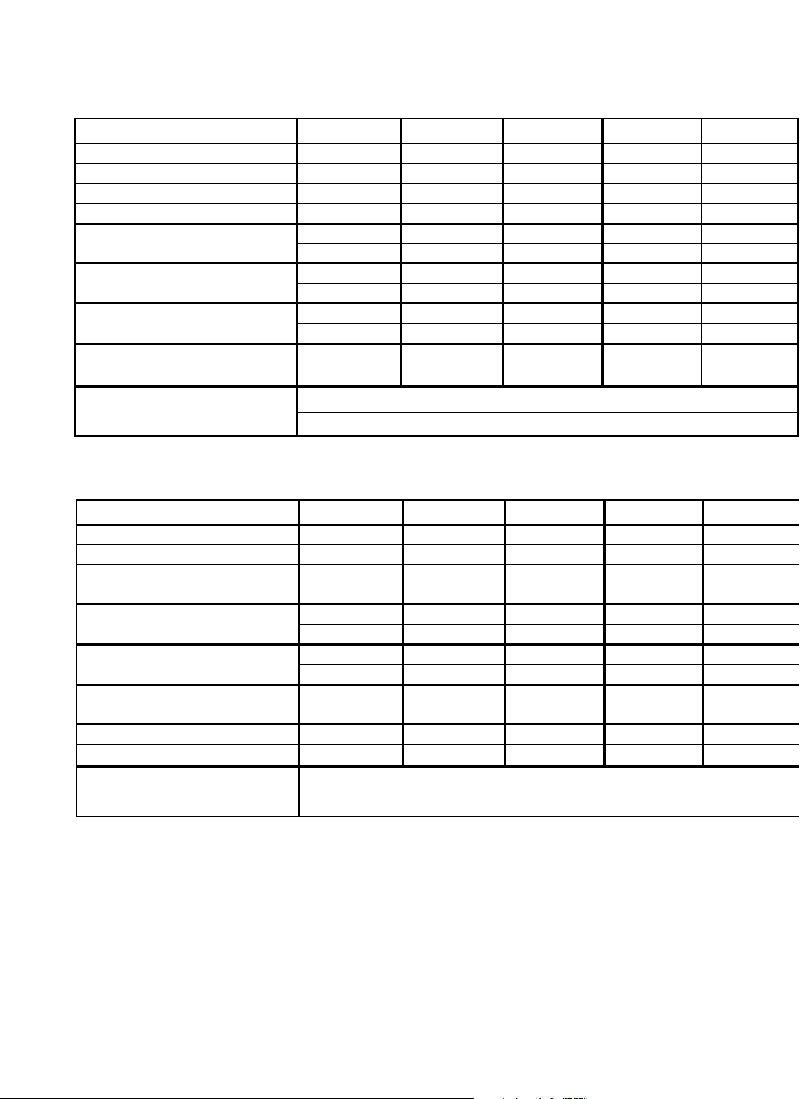
GENERAL SPECIFICATIONS
Nominal kW 357.5 10 15
Fan Diameter
in. (mm) 12 (305) 12 (305) 12 (305) 12 (305) 16 (406)
Air Delivery CFM (m
3
/hr) 700 (1190) 700 (1190) 700 (1190) 700 (1190) 1450 (2460)
Approx. Air Velocity ft/m (m/s) 785 (4.0) 785 (4.0) 785 (4.0) 785 (4.0) 950 (4.8)
Horizontal Throw ft. (m) 22 (6.7) 22 (6.7) 22 (6.7) 22 (6.7) 35 (10.7)
Max. Mounting Height* (ft.) 8.5 8.5 8.5 8.5 11.5
horizontal (to underside) (m) 2.6 2.6 2.6 2.6 3.5
Max. Mounting Height* (ft.) 12.8 12.8 12.8 12.8 18.0
45° decline (to underside) (m) 3.9 3.9 3.9 3.9 5.5
Min. Mounting Height
(ft.) 6.0 6.0 6.0 6.0 6.0
(m) 1.8 1.8 1.8 1.8 1.8
Net Weight lbs. (kg) 75.0 (34.1) 75.0 (34.1) 75.0 (34.1) 75.0 (34.1) 90.0 (40.9)
Shipping Weight lbs. (kg) 125.0 (56.8) 125.0 (56.8) 125.0 (56.8) 125.0 (56.8) 140.0 (63.6)
Temperature Limitations Storage: -49°F to 140°F (-45°C to 60°C)
Operating: -49°F to 104°F (-45°C to 40°C)
Nominal kW 20 25 30 35 39
Fan Diameter in. (mm) 16 (406) 20 (508) 20 (508) 20 (508) 20 (508)
Air Delivery CFM (m
3
/hr) 1450 (2460) 2100 (3570) 2100 (3570) 2100 (3570) 2100 (3570)
Approx. Air Velocity
ft/m (m/s) 950 (4.8) 900 (4.6) 900 (4.6) 900 (4.6) 900 (4.6)
Horizontal Throw
ft. (m) 35 (10.7) 44 (13.4) 44 (13.4) 44 (13.4) 44 (13.4)
Max. Mounting Height* (ft.) 11.5 12.3 12.3 12.3 12.3
horizontal (to underside) (m) 3.5 3.7 3.7 3.7 3.7
Max. Mounting Height*
(ft.) 18.0 18.8 18.8 18.8 18.8
45° decline (to underside) (m) 5.5 5.7 5.7 5.7 5.7
Min. Mounting Height (ft.) 6.0 6.0 6.0 6.0 6.0
(m) 1.8 1.8 1.8 1.8 1.8
Net Weight lbs. (kg) 90.0 (40.9) 130 (59.1) 130 (59.1) 130 (59.1)) 130 (59.1)
Shipping Weight lbs. (kg) 140.0 (63.6) 180 (81.8) 180 (81.8) 180 (81.8) 180 (81.8)
Temperature Limitations Storage: -49°F to 140°F (-45°C to 60°C)
Operating: -49°F to 104°F (-45°C to 40°C)
* Maximum mounting height to ensure warm air reaches the floor.
– 9 –

– 10 –
PLEASE ADHERE TO INSTRUCTIONS PUBLISHED IN THIS MANUAL.
Failure to do so may be dangerous and may void certain provisions of your warranty.
For further assistance, please call:
24 Hr. Hotline: 1-800-661-8529
(U.S. and Canada)
Please have model and serial numbers available before calling.
5918 Roper Road
Edmonton, Alberta T6B 3E1
Canada
Phone: 780-466-3178
Fax: 780-468-5904
www.ccithermal.com
LIMITED 1 YEAR WARRANTY
CCI Thermal Technologies Inc. warrants all Ruffneck
TM
CR1 Triton
TM
Series Corrosion-Resistant
Washdown Unit Heaters against defects in materials and workmanship for a period of one (1)
year from date of purchase on the following terms:
1. We will provide replacement parts free of charge as necessary to restore any unit to
operating condition, provided that the inoperative parts be returned to us freight prepaid
and that the replacement parts be accepted freight collect.
2. The complete heater may be returned to our plant for repair or replacement (at our
discretion), provided that all related freight costs be borne by the customer.
3. Corrosion and contamination by dirt, dust, etc. will not be considered as defects and,
therefore, are not warrantable.
4. The heater must not be modified in any way.
5. The heater must be installed, used and stored only in accordance with the owner’s
manual and placarded information.
This warranty shall be limited to the actual equipment involved and, under no circumstances,
shall include or extend to installation or removal costs, or to consequential losses or damages.
 Loading...