

Page 1

TM
ISO 9001
POCC CA. ГБ06.B00913
OWNER’S MANUAL
CF1 ProVector® Series
Electric Convection Air Heaters for Hazardous Locations
This manual covers installation, maintenance, repair and parts.
APPROVED LOCATIONS
Electric convection air heaters have an
EC-Type Examination Certificate
Demko No. 02ATEX0152068X for Ex d IIB, IIC T2-T4 Gb
-45°C (-49°F) ≤ Ta ≤ 40°C (104°F)
0359 II 2 G IECEx UL 11.0020X
For Product Temperature Codes refer to
CF1 Technical Data Chart in this manual.
Equipment or Protective System Intended
for use in Potentially Explosive
Atmospheres Directive 94/9/EC.
Compliance with the Essential Health and
Safety Requirements has been assured by
compliance with:
EN 60079-0: 2009, EN 60079-1: 2007
IEC 60079-0: 2007, IEC 60079-1: 2007
WARNING!
READ ALL IMPORTANT NOTICES ON PAGE 3.
ProVector® and Ruffneck™ are registered trademarks.
Copyright© 2013. All rights reserved.
MODEL CODING
CF1 220 1 50 - 012 - T2 - IIB - T
MODEL SERIES
VOLTAGE
220V
230V
240V
254V
380V
400V
415V
PHASE
UNITS IN
SINGLE PHASE
ONLY
T-CODE
FREQUENCY
50 or 60 HERTZ
0075 - 0.75kW 017 - 1.70kW 044 - 4.40kW
0083 - 0.83kW 018 - 1.80kW 048 - 4.80kW
009 - 0.90kW 023 - 2.30kW 053 - 5.30kW
010 - 1.00kW 025 - 2.50kW 057 - 5.70kW
011 - 1.10kW 027 - 2.70kW 064 - 6.40kW
012 - 1.20kW 030 - 3.00kW 070 - 7.00kW
013 - 1.30kW 033 - 3.33kW 076 - 7.60kW
014 - 1.40KW 036 - 3.60kW
015 - 1.50kW 040 - 4.00kW
T2 - 300ºC (572ºF)
T3 - 200ºC (392ºF)
T4 - 135°C (275ºF)
KILOWATTS
BUILT-IN
T'STAT
ADD 'T' FOR
T'STAT
HAZARDOUS
LOCATION
IIB
IIC
Part No. 8409.Rev.9.02
Printed in Canada
Issue Date: August 2013
– 1 –
Page 2
Lock the switch in the “OFF” (open) position and/or tag the switch to prevent unexpected power application.
This heater should only be serviced by personnel with heating and hazardous location equipment experience.
Disconnect heater from the power supply before opening enclosures or servicing heater.
For heaters marked "IIC", ensure to loosen the setscrew before removing the cover.
HEATER MAINTENANCE CHECKLIST
Heater Model: _________________________ Serial No.: ___________________________
Date of Maintenance: ___________________ Maintenance Done By: _________________
Comments: _________________________________________________________________
__________________________________________________________________________
PERIODIC (before and as required during heating season)
1. CLEAN
o Finned Tubes
o Cabinet top and below unit
Remove dust using compressed air. Do not spray with water or solvents.
Do not immerse in water or solvents.
WARNING:
2. CHECK
o All explosion-proof covers for tightness.
ANNUAL (before heating season)
1. ELECTRICAL
o Check all terminal connections and conductors. Tighten loose connections.
Conductors with damaged insulation must be replaced.
o Check all: 1. Service supply conduits, unions, and plugs for damaged items, and replace with
Ex certified components suitable for the appropriate hazardous atmospheres.
2. Heater unions, conduits, and plugs for damage and replace with Ex certified
factory replacement parts.
3. Threaded joints are wrench tight.
2. MECHANICAL
o Check all enclosures. Inside of enclosures must be clean, dry and free of foreign materials.
Note: Enclosure joints are metal to metal. Do not use gasket material or sealant in joints.
o Check the tightness of all hardware. All nuts and bolts must be tight.
o Turn heater on for a minimum of five minutes. Check for warm air exiting heater through
top vents.
– 2 –
For assistance, please call
Toll Free: 1-800-661-8529 (24 hrs)
U.S. & Canada
Page 3

IMPORTANT NOTICES
WARNING:
Read and adhere to the following. Failure to do so may result in severe or fatal injury.
1. Read and comply with all instructions in this manual.
2. Heater is to be used only in atmospheres having an
ignition temperature higher than the heater’s maximum
rated operating temperature, as shown on the heater
data plate. Refer to applicable electrical codes for
additional information.
3. To reduce the risk of fire or explosion, do not install
where the marked operating temperature exceeds the
ignition temperature of the hazardous atmosphere.
4. Heater to be used only in the hazardous locations
indicated on the heater data plate.
5. Heater is for dry, indoor use only. Do not immerse in
water. Do not store or use in areas exposed to rain
or snow.
6. Use supply wires suitable for 90°C (194°F) service.
7. Maximum ambient operating temperature 40°C
(104°F).
8. Heater is to be connected and serviced only by a
qualified electrician experienced with hazardous
location equipment.
9. Heater requires a minimum clearance of 9.5 mm
(3/8”) to all the vertical surfaces and must be mounted
a minimum of 203 mm (8”) off the floor. To ensure
adequate airflow, a minimum clearance of 203 mm
(8”) below and 457 mm (18”) above the heater cabinet
must be maintained.
10. Ensure external field-installed thermostat is suitable for
the application.
11. Installation and wiring of the heater must adhere to all
applicable codes.
12. Before opening any enclosures, disconnect the heater
from the power supply. Lock the switch in the “OFF”
(open) position and/or tag the switch to prevent
unexpected power application.
13. External surfaces get hot and can cause burns with
prolonged contact.
14. Ensure unit is permanently mounted level on a vertical
surface using factory mounting brackets.
15. Heater must be kept clean. When operating in a dirty
environment, regularly clean the finned tubes, top
vents, and keep bottom opening free of obstructions.
Follow the recommended maintenance procedures.
Refer to the “Heater Maintenance Checklist” section for
details.
16. Do not operate the heater in atmosphere corrosive to
steel or aluminum.
17. Use factory approved replacement parts only.
18. Heater should be repaired by qualified personnel only.
19. To reduce the risk of ignition of hazardous
atmospheres, conduit runs must have a conduit
seal connected within 152 mm (6”) of the enclosure.
Conduit seals are not required in factory-installed
conduits.
20. A stopping box, Ex certified for the same potentially
explosive atmospheres as the heater, is required to be
fitted immediately adjacent to the field entry.
21. If there are any questions or concerns regarding the
heater, contact the factory. Refer to the last page of
this manual for details.
22. For heaters that are identified as “suitable for storage
temperatures up to 150°C (302°F) the installer must
ensure that the supply conductors are rated for 150°C
(302°F) and stopping box sealants are rated for 150°C
(302°F).
23. The heater must be allowed to cool down for a period
of 2 minutes after operating before any enclosure
covers can be removed.
WARRANTY WILL BE VOID
IF INSTRUCTIONS ARE NOT FOLLOWED
INSTALLATION
The installation instructions provide a general guideline for the installation and wiring of the heater.
All applicable codes must be adhered to.
MECHANICAL
Heaters must be installed as follows:
LOCATION
1. The air discharge is not directed at a thermostat.
2. The air discharge is across areas of heat loss, such as windows.
3. If equipment freeze protection is of importance, locate heater as close to equipment as possible.
MOUNTING
1. Heater must be mounted level on a vertical surface using the factory supplied mounting brackets
such that there are no obstructions to impede air inlet or discharge (Figure 1b & 3).
2. The mounting surface must be strong enough to:
a. support the heater’s weight, refer to “Specifications” section,
b. withstand abusive situations such as transportable installations of the heater.
– 3 –
Page 4

3. Secure mounting brackets to vertical surface
with the top mounting hole 38 mm (1.5") below
the desired top surface height (Figure 1a). Refer
to Figure 2 for physical dimensions and Figure
3 for required installation clearances. Mounting
brackets are to be spaced to match the slots in
the rear panel of heater cabinet.
4. After mounting brackets are secured, tilt the
heater and lower it onto the top tabs of the
mounting bracket such that the tabs go into the
mounting slots on the rear panel of the heater
cabinet (Figure 1b).
5. Carefully swing the bottom of the heater into the
mounting brackets so that it is resting on the
bottom tab (Figure 1b).
6. Insert the securing screw through the bottom
mounting bracket tab and into the cabinet to keep
the heater from dislodging from the mounting
bracket (Figure 1b).
7. Caution: Use fasteners with yield stress greater
than or equal to 58ksi (400MPa).
Note:
Figures 1-3 are shown with optional built-in room thermostat.
FIGURE 1a
FIGURE 1b
Mounting Bracket
38.0 mm (1.5")
Securing
Screw
Top Tab Detail
Bottom Tab Detail
FIGURE 2: Physical Dimensions
Notes: Heaters with built-in thermostat come with tube extensions.
– 4 –
Page 5
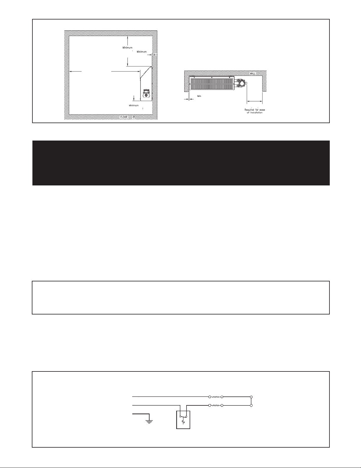
FIGURE 3: Installation Clearances
203.0 mm (8.0”)
9.5 mm
(0.375”)
457.0 mm
(18.0”)
305.0 mm
(12.0”)
9.5 mm
(0.375”)
1219.0 mm (48.0”)
Required for ease of
installation and servicing
ELECTRICAL
WARNING
Disconnect the power supply before installation of the heater. Lock the switch in
the “OFF” (open) position and/or tag the switch to prevent unexpected power application.
For heaters marked "IIC", ensure to loosen the setscrew before removing the cover.
Installation and wiring of the heater must adhere to all applicable codes.
Allow the heater to cool down for a period of 2 minutes after operating before removing any enclosure covers.
GENERAL
1. Use only copper conductors and approved explosion-proof wiring methods during installation. Refer to the
“Technical Data” Table or heater data plate for the voltage, amperage and wattage ratings when sizing for
the appropriate conductors. All supply conductors should be rated for operating at temperatures up to 90°C
(194°F).
2. Supply voltage must be within 10% of the data plate rating. External over-current protection is required and
must meet data plate ratings for voltage, amperage and frequency.
FIELD WIRING
1. Heater has been supplied with an enclosure that has a standard M25 adaptor or optional 3/4" NPT threaded
opening or an M32 opening to accommodate the line conductors (see Figure 4 for connection details). Use
wire connectors rated for minimum 90°C (194°F).
NOTE:
1. If remote thermostats other than the factory supplied are used, ensure that they will not allow the room temperature to exceed ambient temperature
limitations of the heater (40°C [104°F]) and are suitable for the area’s hazardous atmosphere classification. When using any control devices, ensure
that the voltage and amperage ratings match the heater’s electrical ratings. If not, a contactor may be required.
2. For heaters that are identified as “suitable for storage temperatures up to 150°C (302°F) the installer must ensure that the supply conductors are
rated for 150°C (302°F) and stopping box sealants are rated for 150°C (302°F).
FINAL INSPECTION
1. Before application of electrical power:
a. check that all connections are secured and comply with the wiring diagram (see Figure 4) and
applicable code requirements,
b. confirm that the supply voltage is compatible with the data plate specifications,
c. remove any foreign objects from the heater, and
d. ensure all external fittings and enclosure covers are secured.
FIGURE 4: Wiring Diagram for remote mount and built-in room thermostats
Element
Element
* On 120V units
L1 represents
neutral
L1*
L2
Room
Thermostat
– 5 –
Page 6

REPAIR AND REPLACEMENT
WARNING
Disconnect the power supply before installation of the heater. Lock the switch in the “OFF” (open) position
and/or tag the switch to prevent unexpected power application. Heater surfaces may be hot.
Allow the heater to cool down for a period of 2 minutes after operating before removing any enclosure covers.
FINNED TUBE/ELEMENT ASSEMBLY
A complete finned tube assembly is available from the factory. Refer to Parts Diagram for item numbers.
1. Remove the front cabinet panel (Item #1).
2. Remove convector electrical enclosure’s cover and disconnect wires.
3. De-couple two unions (Item #9) connecting convector enclosure and finned tube extension (Item #7).
4. Remove 3/4” NPT plug (Item #11) from element conduit (Item #10) and then pull out wire connector
and disconnect the wires.
5. De-couple remaining two unions and remove element conduit.
6. Remove union halves and lock-nut (Item #8) from ends of each finned tube requiring replacement
and set aside for re-use on new factory supplied finned/element assemblies.
7. Remove bolts from lower tabs of wall mount brackets (Item #6), remove heater from wall mount
brackets, and loosen the bolts from the finned tube bracket (Item #5).
8. Remove the damaged finned tube/element assemblies and install replacements.
9. Re-assemble heater using the reverse order of the preceding instructions.
Important: All threaded connections must be wrench tight with minimum of 5 turns engagement.
CABINET PANELS AND BRACKETS
Replacement cabinet panels and brackets are available from the factory.
NOTE:
For purposes of safety and convenience, all repairs and maintenance must be done with factory authorized parts and materials.
SPECIFICATIONS
Nominal kW
0.75 - 3.00 (220V) &
3.30 (T2) - 3.60 (T2)
Cabinet Length mm (in) 796 (31.3) 1256 (49.4) 1511 (59.5)
Net Weight kg (lbs) 27 (58) 39 (86) 43.6 (96)
Shipping Weight kg (lbs) 30 (65) 44 (95) 47.6 (105)
Defender® housing is cast aluminum with bolt on cover. Groups IIB only.
Enclosures
Mounting Brackets
Heating Elements
Cabinet Material
Temperature Code Rating T2 - 300°C (572°F); T3 - 200°C (392°F); T4 - 135°C (275°F)
Hazardous Locations Without Built-in T'Stat*
With Built-in T'Stat*
Temperature Limitations
x-Max® housing is extruded aluminum with two screwed on covers. Groups IIC
only. For dry indoor use only. Do not immerse in water. Do not store or use in
areas exposed to rain or snow.
Two 14 Ga. 0.075 in (1.90 mm) galvanized steel.
Two Incoloy® sheathed elements.
14 Ga. steel. Rear panel is galvanized. Front and side panels are baked greengrey epoxy powder coated with five-stage pretreatment, including iron phosphate.
Class I, Div. 1 & 2, Groups A, B, C, & D; Class I, Zones 1 & 2, Groups IIA, IIB
Class I, Div. 1 & 2, Groups A, B, C & D; Class I, Zones 1 & 2, Groups IIA, IIB & IIC
Operational: -45°C to 40°C (-49°F to 104°F )
Storage: -45°C to 80°C (-49°F to 176°F)
3.00 - 4.40 & 4.80 (240V)
4.80 (380V) - 7.60
& IIC
*Hazardous location ratings are dependant on the junction box used.
Please consult a customer service representative or the unit data plate for actual location ratings.
– 6 –
Page 7

PARTS DIAGRAM
IIB BUILT IN IIB
Item
#
1
2
3
4
5
6
7
Finned Tube Assy c/w Element
8
9
Union, 3/4" NPT Male/Female CE IIC
10
11
12
Kit, Group B, (IIB) CE Enclosure
13
14
15
Wire Connector, 150°C (302°F)
16
17
18
Fork Connector, 12-10GA #10
Wire Connector, 300°C (+) 572°F (+)
19
20
Kit, Group A, B, C & D (IIC) x-Max® Encl.
21
22
23
Description
Panel, Front
Panel, Back
Panel, Right
Panel, Left
Bracket, Finned Tube
Kit, Wall Mounting
Nut, 3/4" Aluminum Lock
Conduit, Element
Plug, 3/4" Ex-proof CE
Enclosure, Convector CE
Kit, Built-in XCT T'stat CE
Screw, 10-24 x 1/2 in Thd Ct
Tube, Convector Extension
Kit, Built-in XT T'stat
Ground Lug CE
Ground Lug 14-6 gauge wire
796 mm (31.3")
Cabinet Length
IIC
1256 mm (49.4")
Cabinet Length
IIC
1511 mm (59.5")
Cabinet Length
Part # Qty Part # Qty Part # Qty
6488
6487
6491
6492
6485
6602
*
6449
9627
6497
7994
8024
7992
8503
**
4972
2088
6529
7202
9251
9252
7995
2793
20
1
1
1
1
1
1
2
4
4
1
2
1
1
1
**
2
1
2
1
1
1
1
6493
6494
6491
6492
6485
6602
*
6449
9627
6497
7994
8024
7992
8503
**
4972
2088
6529
7202
9251
9252
7995
2793
21
1
1
1
1
1
1
2
4
4
1
2
1
1
1
**
2
1
2
1
1
1
1
6490
6489
6491
9492
6485
6602
*
6449
9627
6497
7994
8024
7992
8503
**
4972
2088
6529
7202
9251
9252
7995
2793
1
1
1
1
1
1
2
4
4
1
2
1
1
1
**
22
2
1
2
1
1
1
1
NOTE:
* Contact factory for replacement finned tube kit.
** Customer supplied. Quantity varies: 1 for built-in t’stat option; 2 for remote t’stat option.
Dimensions of flameproof joints are other than the relevant minimum or maximum specified in Table 2 of IEC 60079-1:2007. Contact Manufacturer for
information regarding the dimensions of the flameproof joints.
– 7 –
Page 8
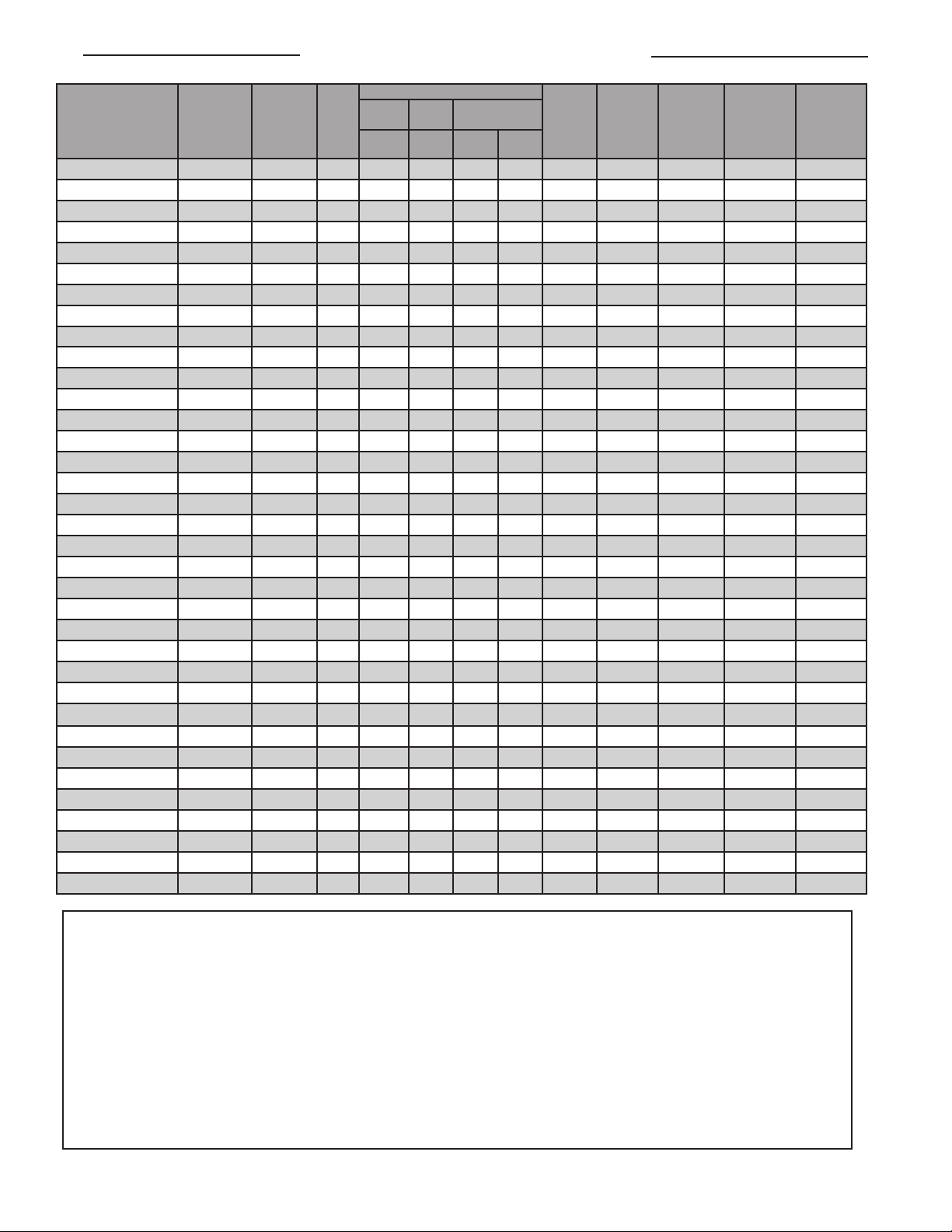
CF1 TECHNICAL DATA
MODEL NUMBER
CF1-220150-010-T4 1.0 (3412) 220
CF1-220150-015-T3 1.5 (5118) 220
CF1-220150-030-T2 3.0 (10236) 220
CF1-220150-040-T3 4.0 (13648) 220
CF1-220150-064-T2** 6.4 (21837) 220
CF1-230150-011-T4 1.1 (3753) 230
CF1-230150-017-T3 1.7 (5801) 230
CF1-230150-030-T3 3.0 (10236) 230
CF1-230150-033-T2 3.3 (11260) 230
CF1-230150-044-T2 4.4 (15013) 230
CF1-230150-070-T2** 7.0 (23885) 230
CF1-240150-012-T4 1.2 (4095) 240
CF1-240150-018-T3 1.8 (6142) 240
CF1-240150-030-T3 3.0 (10236) 240
CF1-240150-036-T2 3.6 (12284) 240
CF1-240150-048-T2 4.8 (16378) 240
CF1-240150-076-T2** 7.6 (25932) 240
CF1-254150-030-T3 3.0 (10236) 254
CF1-380150-0075-T4 0.75 (2559) 380
CF1-380150-011-T4 1.1 (3753) 380
CF1-380150-023-T3 2.3 (7848) 380
CF1-380150-030-T3 3.0 (10236) 380
CF1-380150-036-T3 3.6 (12284) 380
CF1-380150-048-T2 4.8 (16378) 380
CF1-400150-0083-T4 0.83 (2832) 400
CF1-400150-013-T4 1.3 (4436) 400
CF1-400150-025-T3 2.5 (8530) 400
CF1-400150-033-T3 3.3 (11260) 400
CF1-400150-036-T3 3.6 (12284) 400
CF1-400150-053-T2 5.3 (18084) 400
CF1-415150-009-T4 0.90 (3071) 415
CF1-415150-014-T4 1.4 (4777) 415
CF1-415150-027-T2 2.7 (9213) 415
CF1-415150-036-T3 3.6 (12284) 415
CF1-415150-057-T2 5.7 (19449) 415
kW
(BTU/hr)
UNIT
VOLTAGE
(VOLTS)
GAS GROUP
BASIC
IIB + H2IIB IIC
UNIT
W/O
T'STAT
W/
T'STAT
W/O
T'STAT
- - 12 13.8 15 796 (31.3) T2
- - 10 18.3 20 1256 (49.4) T3
- - - 8 29.0 30 1511 (59.5) T2
- - 10 14.4 15 796 (31.3) T2
- - 10 19.2 20 1256 (49.4) T2
- - - 8 30.3 35 1511 (59.5) T2
- - 10 15.0 20 796 (31.3) T2
- - 10 20.0 25 1256 (49.4) T2
- - - 8 31.7 35 1511 (59.5) T2
- - 12 5.9 15 796 (31.3) T3
- - 12 12.5 15 1511 (59.5) T2
- - 12 6.3 15 796 (31.3) T3
- - 12 13.2 15 1511 (59.5) T2
- - 12 6.5 15 796 (31.3) T2
- - 12 13.7 15 1511 (59.5) T2
W/
T'STAT
SUPPLY
WIRE
SIZE
(AWG)***
12 4.6 15 796 (31.3) T4
12 6.9 15 796 (31.3) T3
12 4.8 15 796 (31.3) T4
12 7.2 15 796 (31.3) T3
12 13.0 15 1256 (49.4) T3
12 5.0 15 796 (31.3) T4
12 7.5 15 796 (31.3) T3
12 12.5 15 1256 (49.4) T3
12 11.8 15 1256 (49.4) T3
12 2.0 15 796 (31.3) T4
12 3.0 15 796 (31.3) T4
12 7.9 15 1256 (49.4) T3
12 9.4 15 1256 (49.4) T3
12 2.1 15 796 (31.3) T4
12 3.1 15 796 (31.3) T4
12 8.3 15 1256 (49.4) T3
12 9.0 15 1256 (49.4) T3
12 2.2 15 796 (31.3) T4
12 3.2 15 796 (31.3) T4
12 8.7 15 1256 (49.4) T3
UNIT
CURRENT
(AMPS)
MAXIMUM
CIRCUIT
FUSE
(AMPS)*
CABINET
LENGTH
mm (in)
TEMP.
CODE
All units are single phase
Units can be operated at 50 or 60 Hz
* Or equivalent breaker as per local electrical inspection authority requirements
** Optional thermostats not available as it exceeds current rated capacity.
*** Ensure supply wire size adheres to applicable local and national electrical codes.
NOTES
1. Heater is functioning normally if, at rated voltage, the current draw is within 10% of the value in this table.
2. Operation at lower voltages that rated will result in reduced output and current draw.
Actual Output (kW) = [(Supply Voltage)2 ÷ (Rated Voltage)2] × Rated Unit Wattage (kW)
3. Add suffix "T" for optional built-in thermostat. Thermostat not available on IIB + H2 models.
4. Add suffix "H" for high-temperature ambient storage option. High temperature storage option is not available with thermostat option. Not available on IIB
models.
5. For IIB model with XCT built-in thermostat - Class I, Div. 1 & 2, Groups C & D; Zones 1 & 2, Groups IIA and IIB
6. For IIC model with XTWA built-in thermostat - Class I, Div. 1 & 2, Groups A,B,C & D; Zones 1 & 2, Groups IIA, IIB, IIC
7. IIC Grouping units come with x-Max® housing
8. Remote mounted, Defender, explosion-proof room thermostats are not suitable for Group B & IIC applications
9. Temperature code ratings: T2 - 300°C (572°F), T3 - 200°C (392°F), T4 - 135°C (275°F)
– 8 –
Page 9

NOTES
– 9 –
Page 10

NOTES
– 10 –
Page 11
DIRECTIVE 2003/108/EC AMMENDMENT TO THE DIRECTIVE 2002/96/EC OF THE
EUROPEAN PARLIAMENT AND OF THE COUNCIL on waste electrical and electronic
equipment (WEEE).
1. The equipment that you bought is WEEE marked and has required the extraction and
use of natural resources for its production. It may contain substances that could impact
health and the environment. As such it is a requirement not to dispose of WEEE marked
equipment as unsorted municipal waste and to collect such WEEE marked equipment
separately.
2. In order to avoid the dissemination of those substances in our environment and to
diminish the pressure on natural resources, we encourage you to use the appropriate
take-back systems in your area. Those systems will reuse or recycle most if not all of
the materials of your and life equipment in a sound way.
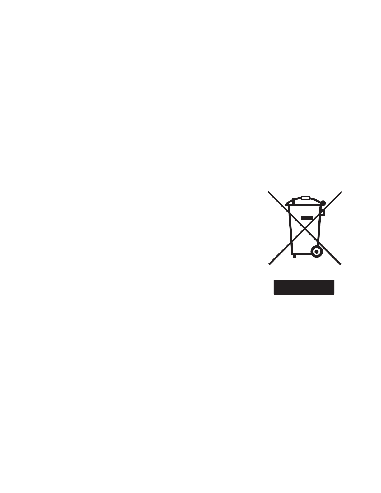
3. The crossed-out wheeled bin symbol on this equipment invites you to use those
systems.
4. If you need more information on collection, reuse and recycling systems in your area,
please contact your local or regional waste management administration.
– 11 –
Page 12

5918 Roper Road, Edmonton, Alberta, Canada T6B 3E1
Phone: (780) 466-3178 Fax: (780) 468-5904
PLEASE ADHERE TO INSTRUCTIONS PUBLISHED IN THIS MANUAL.
Failure to do so may be dangerous and may void certain provisions of your warranty.
For further assistance, please call:
24 Hr. Hotline: 1-800-661-8529
(U.S.A. and Canada)
Please have model and serial numbers available before calling.
WARRANTY: Under normal use the Company
warrants to the purchaser that defects in material or
workmanship will be repaired or replaced
without charge for a period of 18 months from
date of shipment, or 12 months from the start date of
product was purchased for authorized repair or
replacement within the terms of this warranty.
Subject to State or Provincial law to the contrary, the
Company will not be responsible for any expense for
installation, removal from service, transportation, or
damages of any type whatsoever, including damages
arising from lack of use, business interruptions, or
incidental or consequential damages.
The Company cannot anticipate or control the
conditions of product usage and therefore
accepts no responsibility for the safe application and
suitability of its products when used alone or in
combination with other products. Tests for the safe
application and suitability of the products are the sole
responsibility of the user.
This warranty will be void if, in the judgment of the
Company, the damage, failure or defect is the result of:
• vibration, radiation, erosion, corrosion, process
contamination, abnormal process conditions,
temperature and pressures, unusual surges or
pulsation, fouling, ordinary wear and tear, lack of
maintenance, incorrectly applied utilities such as
voltage, air, gas, water, and others or any
combination of the aforementioned causes not
• any act or omission by the Purchaser, its agents,
servants or independent contractors which for
greater certainty, but not so as to limit the generality
of the foregoing, includes physical, chemical or
mechanical abuse, accident, improper
installation of the product, improper storage and
handling of the product, improper application or the
misalignment of parts.
manufacturing defects apparent within 30 days from
the date of installation.
The Company neither assumes nor
authorizes any person to assume for it any other
obligation or liability in connection with the product(s).
The Purchaser agrees that all warranty work required
after the initial commissioning of the product will be
provided only if the Company has been paid by the
Purchaser in full accordance with the terms and
conditions of the contract.
The Purchaser agrees that the Company makes
no warranty or guarantee, express, implied or
statutory, (INCLUDING ANY WARRANTY OF
MERCHANTABILITY OR WARRANTY OF FITNESS
FOR A PARTICULAR PURPOSE) written or oral, of
the Article or incidental labour, except as is expressed
or contained in the agreement herein.
LIABILITY: Technical data contained in the catalog or
on the website is subject to change without notice. The
Company reserves the right to make dimensional and
other design changes as required. The Purchaser
acknowledges the Company shall not be obligated
to modify those articles manufactured before the
formulation of the changes in design or improvements
of the products by the Company.
The Company shall not be liable to compensate or
indemnify the Purchaser, end user or any other party
against any actions, claims, liabilities, injury, loss, loss
of use, loss of business, damages, indirect or conse-
es (including legal expenses), costs, obligations and
causes of action of any kind arising wholly or partly
from negligence or omission of the user or the misuse, incorrect application, unsafe application, incorrect storage and handling, incorrect installation, lack
of maintenance, improper maintenance or improper
operation of products furnished by the Company.
Edmonton
1-800-661-8529
(780) 466-3178
F 780-468-5904
Oakville
1-800-410-3131
(905) 829-4422
F 905-829-4430
Orillia
1-877-325-3473
(705) 325-3473
F 705-325-2106
Greensburg
1-800-473-2402
(812) 663-4141
F 812-663-4202
Houston
1-855-219-2101
(281) 506-2310
F 281-506-2316
Denver
1-855-244-3128
(303) 979-7339
F 303-979-7350
 Loading...