

CC-ISOBUS CCI 50 Operating Instructions Manual
ISOBUS-Terminal CCI 50
ISOBUS implement control
CCI.Cam
Visual implement monitoring
CCI.Control
Documentation and task management
CCI.Tecu
Tractor data
CCI.Command
GPS track guiding and section control
CCI.GPS
GPS settings and tractor geometry
Operating Instructions (EN)

CCI 50
ISOBUS-Terminal
Operating instructions
Reference: Release 5.50

Copyright
© 2017
Competence Center ISOBUS e.V.
Albert-Einstein-Str. 1
D-49076 Osnabrück
Document number: 20170315

Contents
About the CCI 50 i
Available software i
1 Safety 1
1.1 Identification of indications in the operating instructions 1
1.2 Intended use 1
1.3 Safety indications for the operator / user 2
1.4 Safety indications for the installation of electrical devices 3
1.5 Safety indication for the stop switch 4
2 Structure and function 5
2.1 Overview 5
2.2 Nameplate 5
2.3 Operating elements 6
2.3.1 Stop switch 6
2.3.2 ESC button 7
2.3.3 Scroll wheel 7
2.3.4 Function keys 8
2.3.5 Softkey swap 8
2.3.6 Acknowledgement button 8
2.3.7 i button 8
2.3.8 Toggle button 9
2.3.9 Home button 9
2.3.10 ON/OFF 9
2.3.11 Touchscreen 10
2.4 Interfaces 10
3 Set-up for operation 11
3.1 Mounting the terminal 11
3.2 Connecting the terminal 12
4 Operation 13
4.1 Navigation 13
4.2 Entry of values 14
4.2.1 Entering text 16
4.2.2 Entering numerical values 17
4.2.3 Entering a Boolean value 19
4.2.4 Selecting a value from a selection list 20
4.3 Main menu 21
5 Settings 22
5.1 User settings 23
5.1.1 Display lighting 25
5.1.2 Sound 27

5.1.3 App toggling 28
5.2 Country settings 28
5.3 System settings 30
5.3.1 Date and time 31
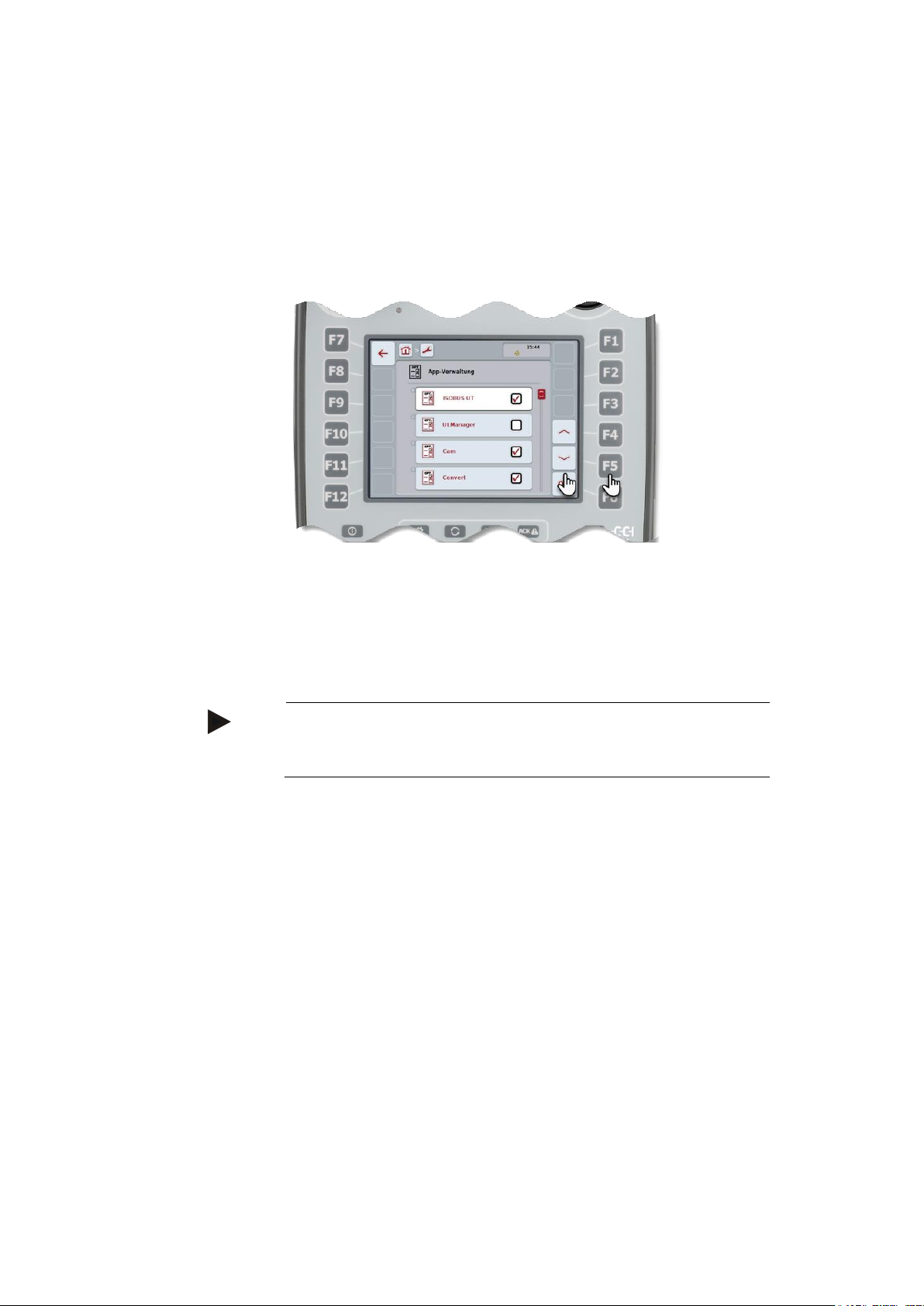
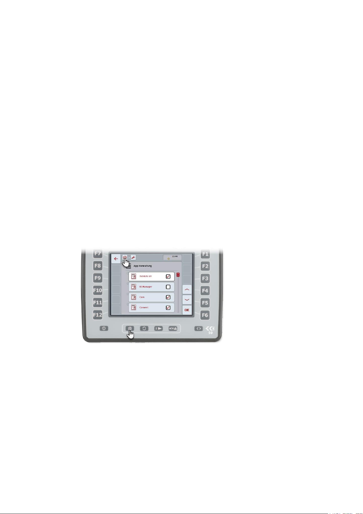
5.3.2 App management 33
5.3.3 CAN 33
5.3.4 Touch calibration 35
5.3.5 Call service area 35
5.3.6 Licence key 35
5.4 Info and diagnostics 37
5.4.1 Terminal 38
5.4.2 Network members 39
5.4.3 Storage 41
5.4.4 Test 42
5.4.5 Show error memory 44
5.4.6 Create screenshot 45
6 ISOBUS auxiliary controls (AUX-Control) 46
7 Troubleshooting 49
7.1 Terminal errors 49
7.2 Error messages 50
8 Glossary 51
9 Index 53
A. Appendix 55
Menu structure 55
Time zones 56

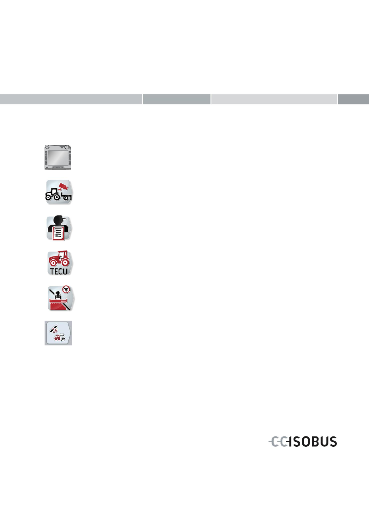
About the CCI 50
CCI.CAM
Visual implement monitoring
CCI.Calc
Pocket calculator
CCI.Convert
Control devices with LH5000, ASD or TUVR
CCI.File
File server
CCI.GPS
GPS settings and tractor geometry
CCI.TECU
Tractor data
ISOBUS UT
ISOBUS implement operation
The CCI 50 is a manufacturer-independent operating terminal for
controlling ISOBUS implements. The range of functions offered by the
terminal is expanded by CCI.Apps.
These operating instructions are an introduction to configuring and
operating the terminal. It is only with knowledge of these operating
instructions that accidental misuse of the terminal can be avoided and
fault-free operation ensured.
These operating instructions must be read and understood prior to
assembly and commissioning of the terminal to prevent problems
during operation. No liability is accepted for damage resulting from
the failure to observe these operating instructions!
Available software
The following CCI.apps are supplied with the terminal:
i

CCI.Command
Parallel Tracking and Section Control
CCI.Control
Documentation and task management
The following CCI.Apps can only be used once released by your dealer or service partner:
ii
1 Safety
Warning - General Hazards!
This occupational safety symbol identifies general safety indications the non-observance of which poses a danger for life and limb.
Carefully observe the indications regarding occupational safety and
exert particular caution in these cases.
Caution!
This caution symbol identifies all safety indications referring to
regulations, directives or working procedures which must be observed. Non-observance can result in damage to or destruction of
the terminal as well as malfunctions.
Note
The note symbol highlights operation tips and other particularly
useful information.
These operating instructions contain basic instructions which must be
observed during configuration, operation and service. As such, it is
absolutely essential to read these operating instructions prior to configuration and operation.
Not only do the general safety indications listed in this "Safety" chapter have to be observed but also the special safety indications appearing in other chapters as well.
1.1 Identification of indications in the operating instructions
The safety indications in these operating instructions are specially
identified:
1.2 Intended use
The terminal is intended exclusively for use with approved ISOBUSimplements and devices in agriculture. Any other installation or
use of the terminal is not included within the manufacturer's area of
responsibility.
The manufacturer accepts no liability for any resulting personal injury
or material damage. Any risks for unintended use are borne solely by
the user.
Observance of the operation and maintenance conditions stipulated
by the manufacturer also form part of intended use.
The accident prevention regulations in force, as well as other generally recognised safety, industrial, medical and traffic laws must be observed. Unauthorised modifications to the device exclude the manufacturer's liability.
1

Safety
1.3 Safety indications for the operator / user
Do not remove any safety mechanisms or signs.
Disconnect the power supply to the terminal during maintenance
work or when using a charging device on the battery of the
towed/production implement.
Never perform maintenance work or repairs when the device is
switched on.
Disconnect the power supply to the terminal beforehand when
welding on the tractor or an attached implement.
Only use a soft cloth moistened with clean water or a small
amount of glass cleaning agent to clean the terminal.
Use your fingertip to operate the buttons. Avoid using your finger
nails.
If, after having read these operating instructions there are sections
which you still do not understand, contact your dealer for clarification before using the terminal.
Carefully read and observe all safety information in the operating
instructions and the safety labels on the terminal. Safety labels
must always be in a proper legible condition. Replace missing or
damaged labels. Ensure that new terminal parts are provided with
the current safety labels. Spare labels can be obtained from your
authorised dealer.
Learn how to use the terminal in accordance with regulations.
Keep the terminal and accessories in good condition.
2

1.4 Safety indications for the installation of electrical devices
Modern farming implements use electronic components and parts the
operation of which can be compromised by electro-magnetic interference from other devices. Such effects can endanger people if the following safety indications are not observed.
In the event of retrofitting electric and electronic devices, and/or
components, in an implement with connection to the on-board network, the user must independently verify whether the installation interferes with vehicle electronics or other components. This is, in particular, applicable to the electronic interference of:
Electronic hoisting gear control
Front hoisting gear
Power take offs
Engine and gears
It must be ensured in particular that the retrofitted electric and electronic components comply with the EMC Directive 89/336/EC in its
respectively valid version and that they bear the CE marking.
In order to retrofit mobile communication systems (e.g. radio, telephone), it is important to meet the following requirements:
Only devices may be installed that are approved in accordance
with valid farming regulations (e.g. BZT (Federal Office for Approval in Telecommunications) approval in Germany).
The device must be properly installed.
The operation of portable or mobile devices inside the vehicle is
only permitted using a connection to a properly installed external
aerial.
The transmitting part must be installed physically and separately
from the vehicle electronics.
When fitting the aerial it must be ensured that the installation is
correctly executed with a good earth connection between the aerial
and vehicle earth.
The implement manufacturer's installation instructions must also
be used for the wiring and installation as well as for the maximum
permitted power consumption.
3

Safety
Caution!
The stop switch has no effect on tractor functions. The power take
off or hydraulic system cannot be placed in a safe state via the
stop switch.
1.5 Safety indication for the stop switch
A safe condition for the connected implement can be established by
pressing the stop-button. In order to do so, the implement must support the stop function.
For further information, please see the operating instructions for your
implement.
4
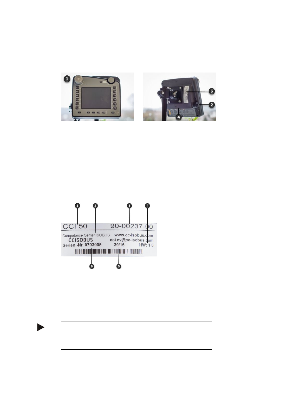
2 Structure and function
Front side
1. Operating elements and
touchscreen
2. USB port
Rear side
3. Nameplate
4. Interface bar
1. Terminal type
2. Manufacturer
3. Manufacturer item number or
material number
4. Hardware version
5. Date of manufacture
(week and year)
6. Serial number
Note
The layout and content of nameplates varies from manufacturer to
manufacturer. Nevertheless, the above information is always
present.
2.1 Overview
2.2 Nameplate
The nameplate features all important terminal information.
5
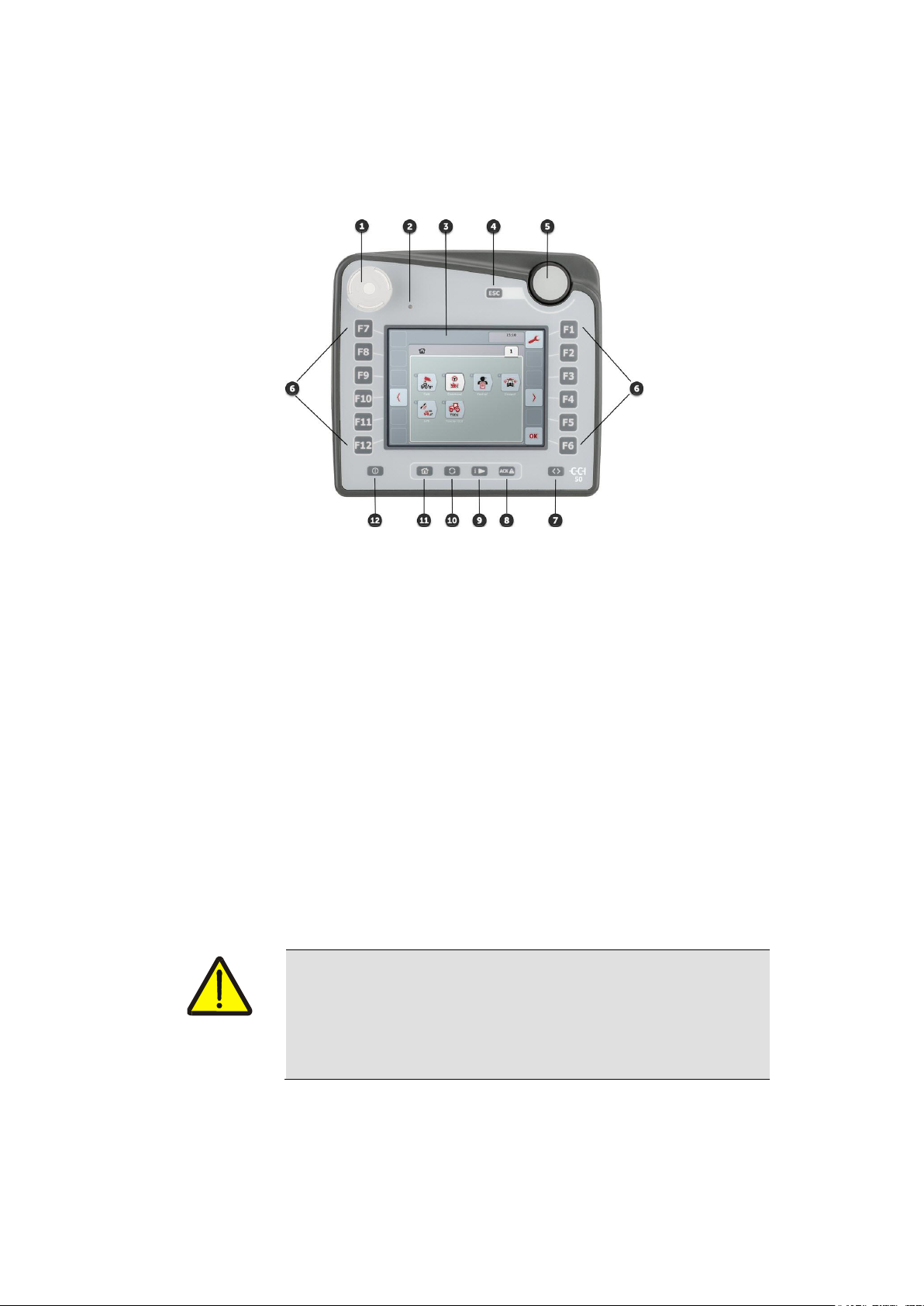
Structure and function
1. Stop switch
2. Brightness sensor
3. Touchscreen with “Main
menu“ operating screen
4. ESC button
5. Scroll wheel
6. Function keys
7. Softkey swap
8. Acknowledgement button
9. i button
10. Toggle button
11. Home button
12. ON/OFF
Warning - Risk of injury due to operating implement!
Not all ISOBUS implements support the stop command. As a result, an implement may continue to operate after the stop switch
has been pressed. This can lead to injuries.
Please refer to the operating instructions of the implement to verify whether the function is supported or not.
2.3 Operating elements
The following operating elements are available on the terminal:
2.3.1 Stop switch
The stop switch is a palm button switch. Press the stop switch until it
locks in place.
Pressing the stop switch sends a stop command (ISO stop) to the
ISOBUS. This command can be evaluated by a connected ISOBUS
implement to initiate the necessary automatic measures in a dangerous situation.
6

2.3.2 ESC button
Note
The hardkey ESC button can only be used if there is an ESC button
present on the operating display.
The hardkey button and touchscreen button have the same function.
Rotation to the right:
The value in an input dialogue for numerical
values is increased.
Switches to the next list element in a selec-
tion list.
Rotation to the left:
The value in an input dialogue for numerical
values is decreased.
Switches to the next previous element in a
selection list.
Press:
Pressing the scroll wheel triggers the same action as pressing an “OK” button.
The changed value in an input dialogue is
applied.
A highlighted list element is selected.
The ESC button is pressed to abort inputs and functions. The modifications made are not applied and the previously valid value is retained.
2.3.3 Scroll wheel
The scroll wheel is used for the direct and quick entry of target values, as well as for scrolling through list elements:
7
Structure and function
Note
Swapping of the softkey bar positions is only available in the implement operation area.
2.3.4 Function keys
Six function keys (F1-F12) are arranged to the right and left of the
touchscreen. Pressing a function key causes the function displayed directly alongside the function key on the operating screen to be performed.
Alternatively press the HMI button on the operating screen.
2.3.5 Softkey swap
The positions of both softkey bars on the left- and right-hand screen
edge are swapped over by pressing the softkey swap button. This allows the terminal to be operated with just one hand.
2.3.6 Acknowledgement button
The acknowledgement button (ACK) is used to confirm error messages.
2.3.7 i button
The i button can be assigned to a frequently used app (see chapter
5.1).
8

2.3.8 Toggle button
Note
With some implements, changing from an active implement will
cause functions running on some implements to automatically
switch off.
For further information on this point consult the implement operating instructions.
Note
With some implements, changing from an active implement will
cause functions running on some implements to automatically
switch off.
For further information on this point consult the implement operating instructions.
Only one app is ever visible on the CCI 50 display. All other apps continue to run in the background.
The quickest way of toggling between apps in a defined sequence is
using the toggle button.
A commonly occurring use, is swapping from CCI.Command to the
ISOBUS implement and back.
You specify the sequence in the user settings (see chapter 5.1.3).
Repeated quick pressing of the toggle button switches sequentially
between apps.
2.3.9 Home button
Pressing the home button takes you directly to the main menu.
Alternatively press the “Home” HMI button on the top edge of the op-
erating screen.
2.3.10 ON/OFF
Switch the terminal on or off using the "ON/OFF" button.
Press and hold the button for approx. 2 seconds.
9
Structure and function
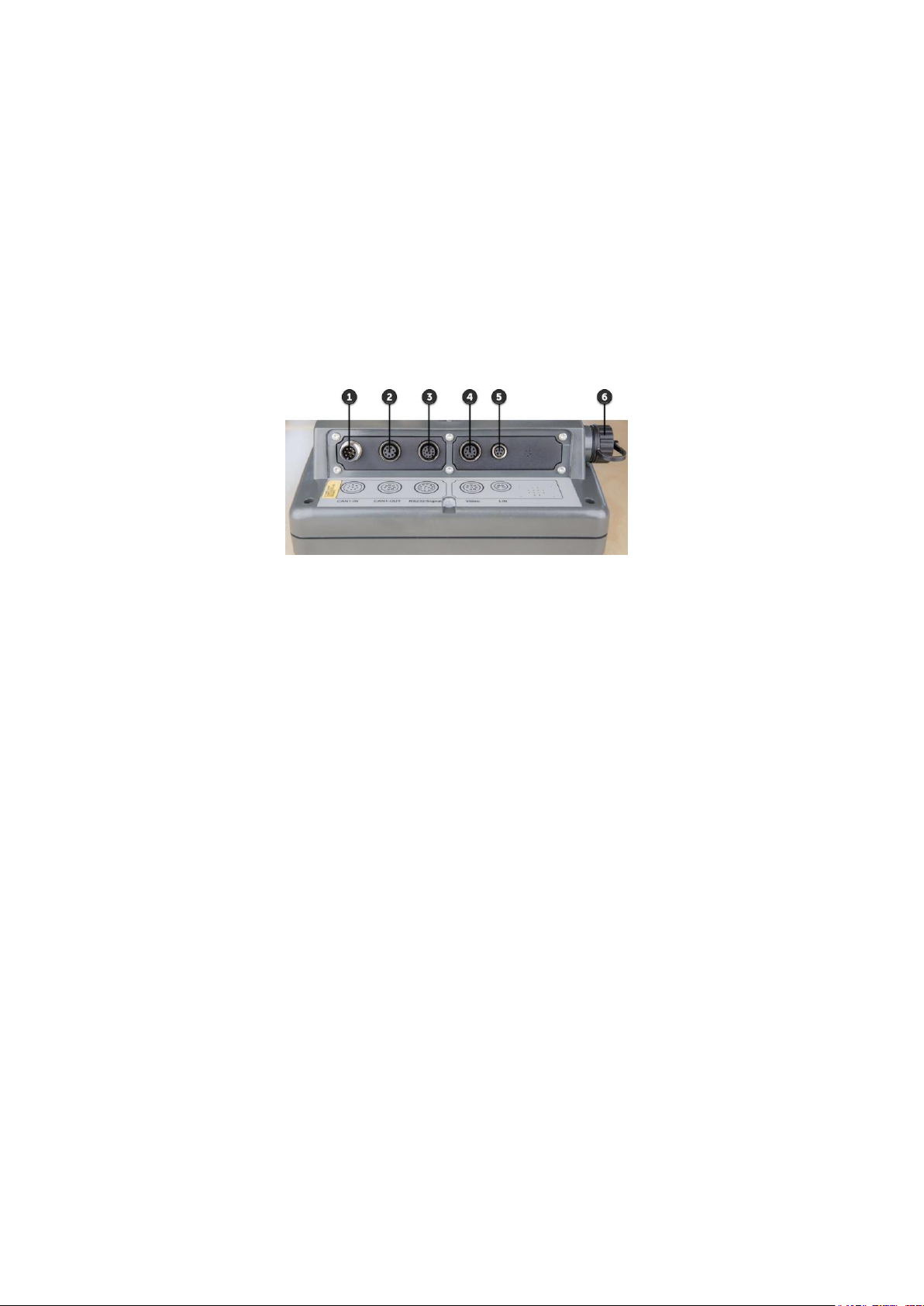
1. CAN1-IN
2. CAN1-OUT
3. 2x RS-232
signal
4. Video
5. LIN
6. USB
2.3.11 Touchscreen
The terminal is equipped with a touchscreen for menu navigation and
the easy input of values and texts directly in the operating screen.
By touching the screen functions can be requested directly and values
changed.
2.4 Interfaces
The interface bar is located on the rear of the terminal.
The USB port is attached on the side of the terminal.
10
3 Set-up for operation
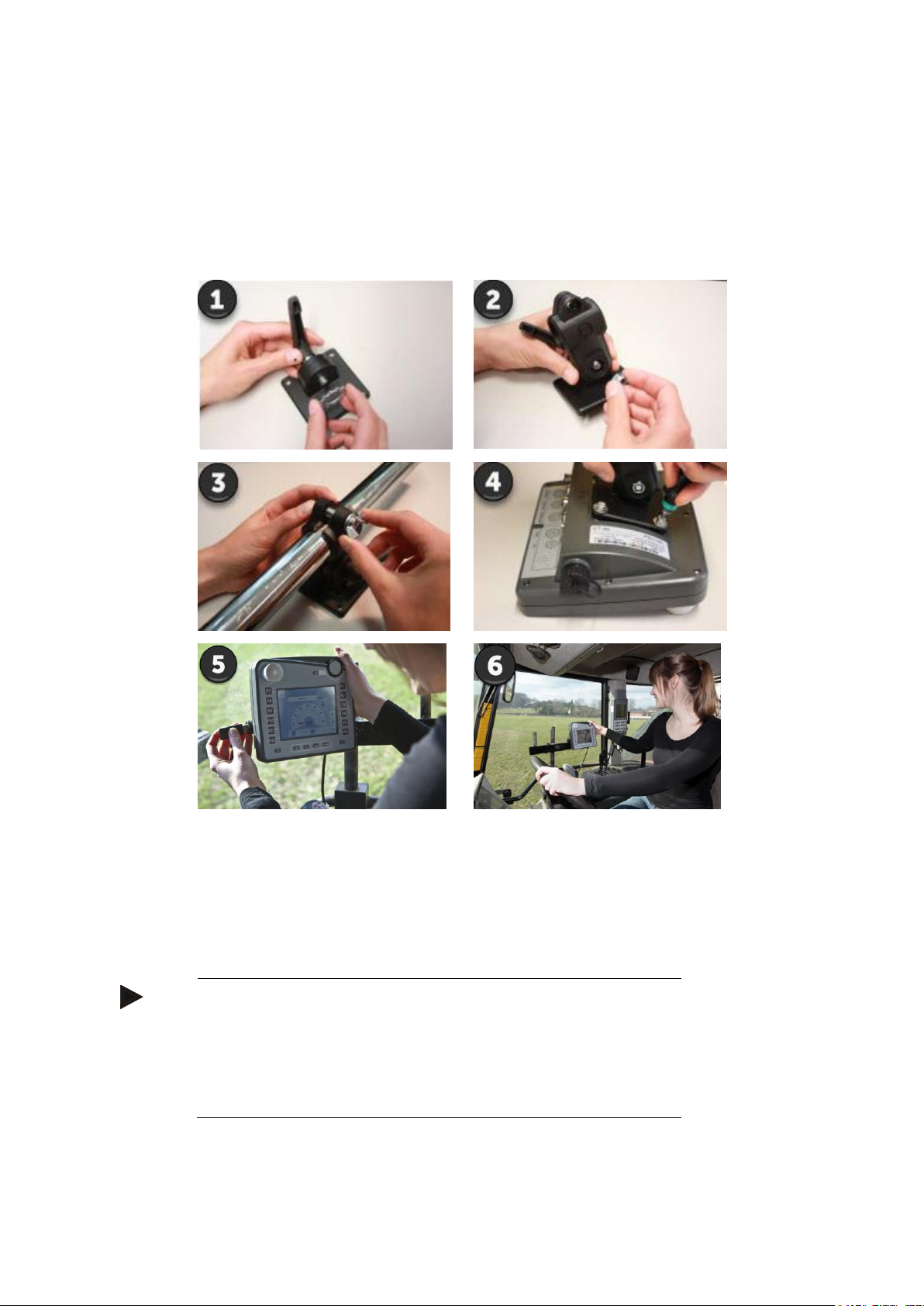
Note
Ensure that the screws are tightened firmly.
Mount the terminal so that it
Is easy to read and operate and
Does not impede the view of the tractor controls or the outside
view.
3.1 Mounting the terminal
The terminal is supplied with a device holder. The terminal is installed
in the tractor cabin using the device holder:
1. Assemble the device holder (Figures 1 and 2).
2. Mount the device holder on the frame and terminal (Figures 3 and
4).
3. Secure the terminal with the device holder in the tractor cab so
that it is in the driver’s field of view. (Figure 5 and 6).
11
Set-up for operation
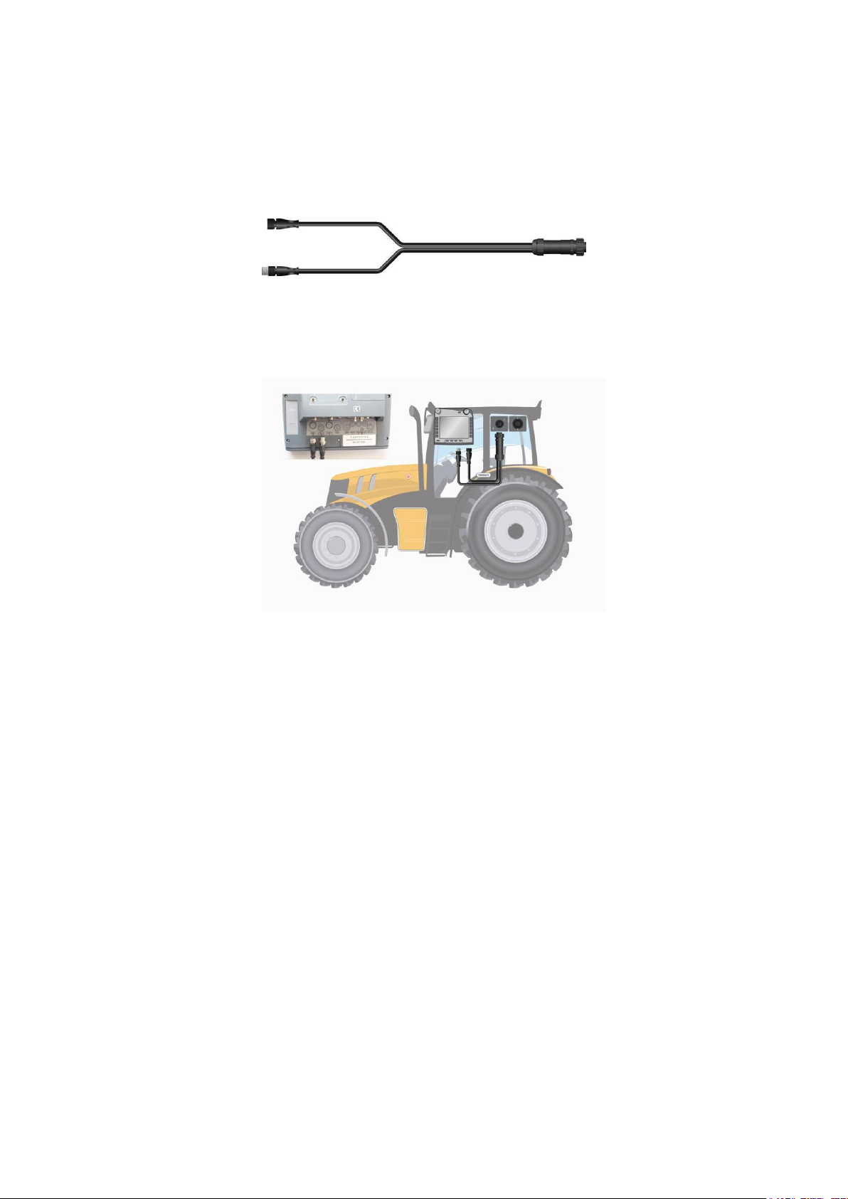
3.2 Connecting the terminal
For connection to ISOBUS and the power supply a type A cable is
necessary:
Connect the "CAN1-IN" and "CAN1-OUT" on the terminal using the
type A cable to the In-cab socket of the tractor.
12
4 Operation
The terminal combines operation with hardkey buttons, scroll wheel
and touchscreen and in this way ensures extremely efficient working.
Working in the field can be disturbed by severe jolting. You can conveniently operate the terminal and ISOBUS implement with one hand
thanks to the softkey swap. Benefit from jolt-secure entry via function keys and scroll wheel. Thanks to mechanical tactile feedback you
do not need to look away from the direction of driving of the implement.
Make any settings when the tractor is stationary. Operate the terminal quickly via the touchscreen.
4.1 Navigation
During daily work with the terminal it must be possible to switch to
and fro between various operating screens and apps. From guidance
mode to the ISOBUS implement, from task and data management to
internet connection settings.
The terminal supports you in quick navigation.
Back to the main menu
Use the home button or the home hardkey button to switch directly
to the main menu:
Breadcrumbs
Each call of a submenu takes you to a deeper level in the menu tree.
Breadcrumbs on the top edge of the screen improve orientation.
Return to a higher level by pressing the breadcrumb. Intermediate
levels are skipped.
13
Operation
Toggling between apps
Using the toggle button you call the apps in an invariable sequence.
Each time the button is pressed you switch to the next app in the sequence.
Using the i button (free button) you always call the same app.
Tab view
Some apps are organised in tabs.
To open a tab,
Press on the tab or
Press on the buttons “Left” (F8) or “Right” (F2)
4.2 Entry of values
In day-to-day work, setpoints must be entered, implement data adjusted or terminal user settings changed.
Values are entered via a screen keyboard, with the scroll wheel or
from a selection list.
Freely enter value
Names or designations are entered via the alphanumeric screen keyboard (4.2.1).
Numbers are entered via the number pad or changed with the scroll
wheel (4.2.2).
14

Making a selection
Confirm by pressing “OK”
Confirm the new value with "OK". The previous value is overwritten:
Press the button "OK" or
press on the scroll wheel.
Cancel with "ESC"
Cancel the entry of a new value by pressing "ESC". The previous
value is retained:
Press the button "ESC" or
press the "ESC” button.
Values specified by the terminal are shown in a selection list.
An element is selected from a selection list using the scroll wheel or
with the buttons “Down” (F5) or “Up” (F4) (4.2.4).
Buttons in the input dialogue
Each entry, change or selection must be confirmed.
Sequence
1. Select the value to be changed in the operating screen.
An input dialogue or a selection list appears.
The operating screen is greyed out.
2. Enter the new value.
3. Confirm the entry with "OK".
The input dialogue is closed.
The operating screen is visible again.
15
Operation
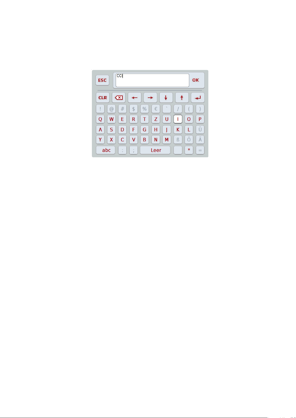
4.2.1 Entering text
Enter text using the alphanumerical screen keyboard.
Change a text as follows:
1. In the operating screen select the value that is to be changed.
The screen keyboard opens.
2. Enter the new value.
3. Confirm your setting with "OK" or
by pressing the scroll wheel.
16
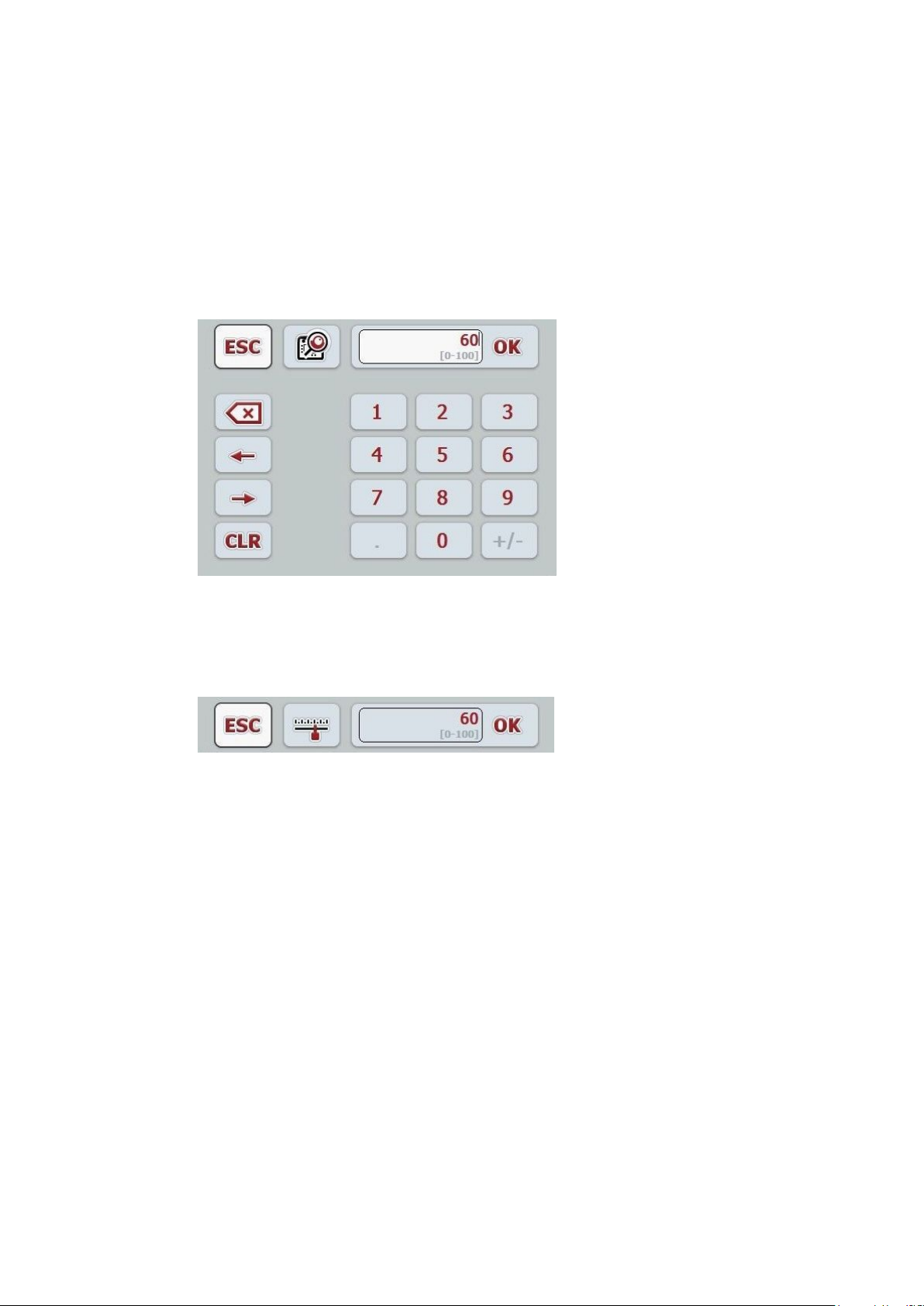
4.2.2 Entering numerical values
The input dialogue for numeric values has three display formats:
Number pad
Enter the value via the number pad or
rotate the scroll wheel.
Scroll wheel
Rotate the scroll wheel.
17
Operation
Note
The next time the input dialogue for numerical values is requested
the last selected display format is immediately displayed.
Note
The input field is highlighted in red if a value is entered outside the
valid value range. In this case enter another value.
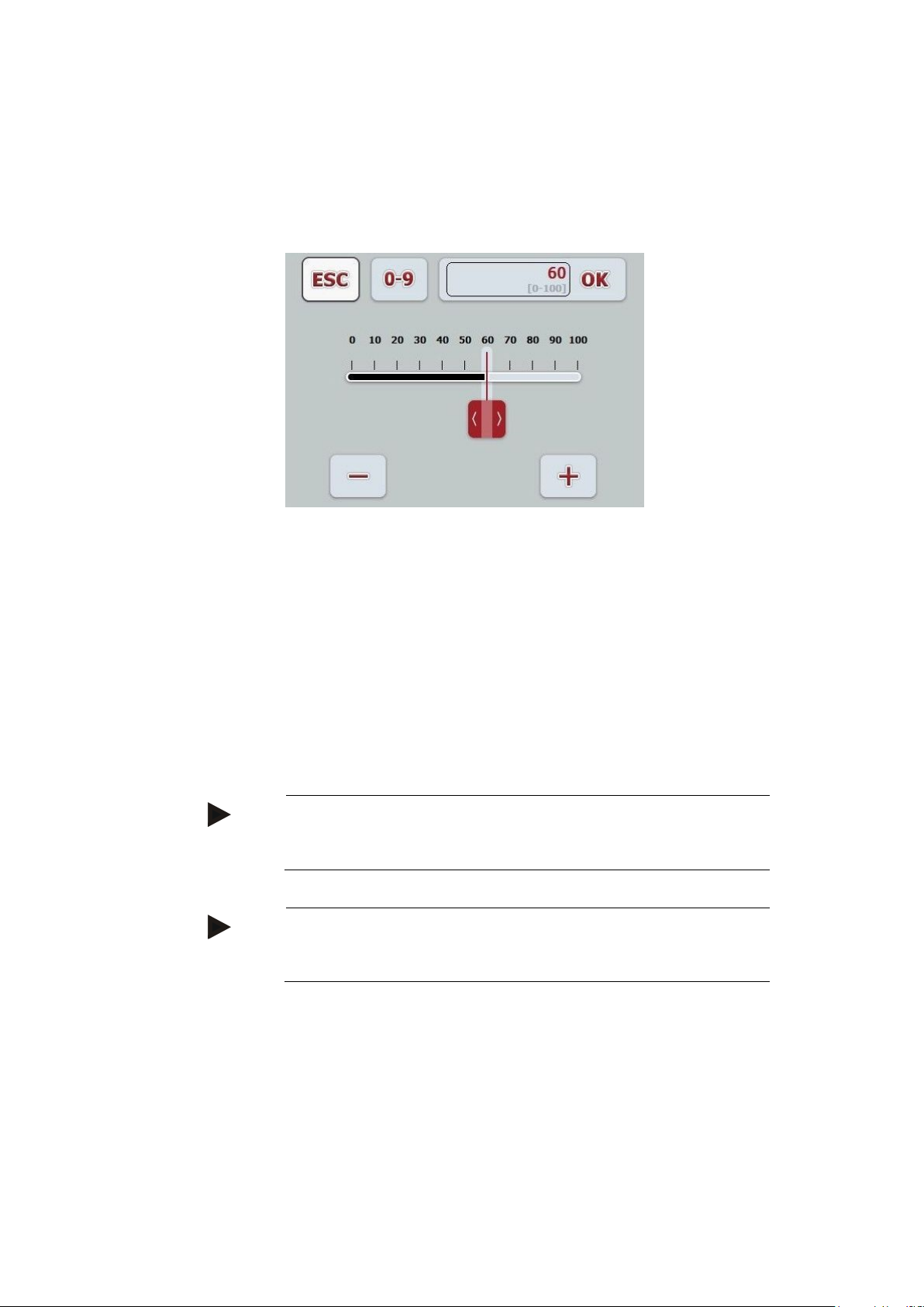
Slider
Drag the slider or
press the "+" and "-" buttons or
rotate the scroll wheel.
The button for selecting the display format, is located between the
buttons "OK" and "ESC":
Change a numerical value as follows:
1. In the operating screen select the value that is to be changed.
The input dialogue is opened.
2. Enter the new value.
3. Confirm your setting with "OK" or
by pressing the scroll wheel.
18
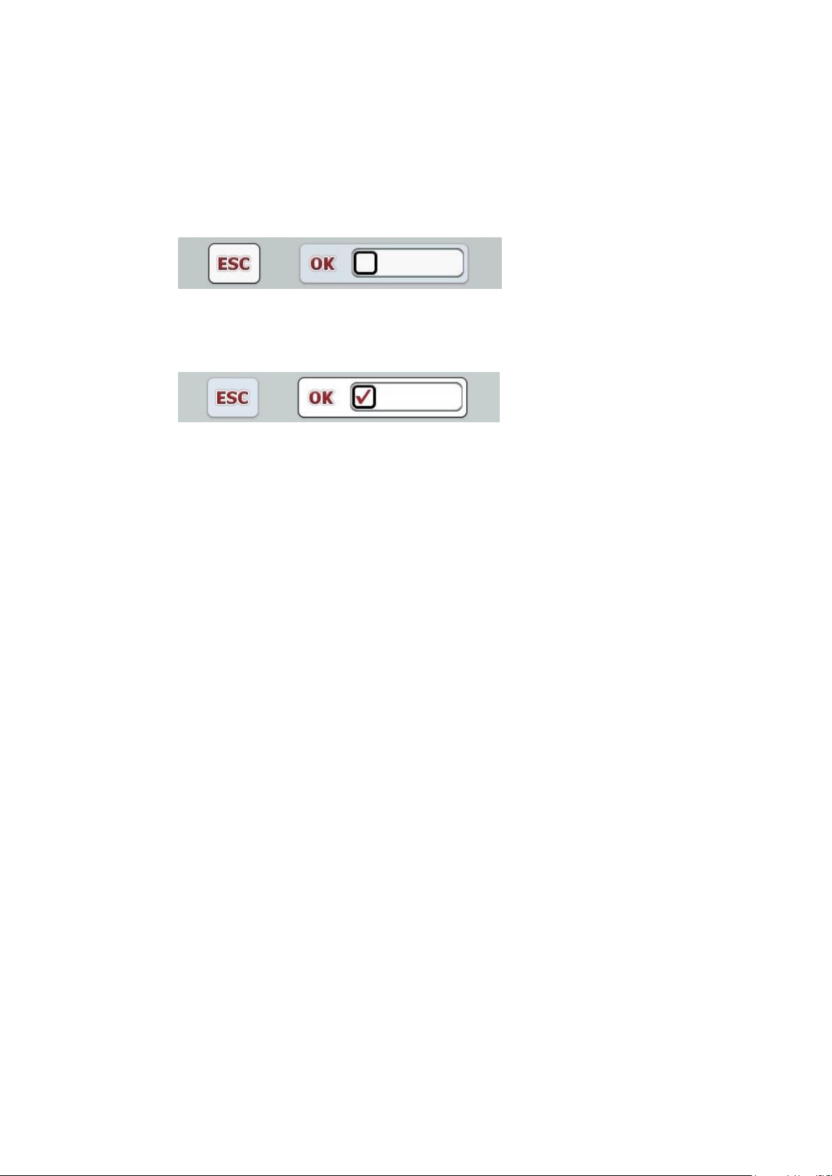
4.2.3 Entering a Boolean value
With a Boolean value it is only possible to select between true and
false, on and off, yes and no.
Display for false, off, no:
Display for true, on, yes:
Change a Boolean value as follows:
1. In the operating screen select the value that is to be changed.
The input dialogue is opened.
2. Press on the checkbox in the input field.
3. Confirm your setting with "OK" or
by pressing the scroll wheel.
19

Operation
Note
You can display the selection list as a single line by pressing: the
selection field. The selection field is located between the buttons
“OK” and "ESC".
4.2.4 Selecting a value from a selection list
Some values can be selected from a selection list.
Select a list value as follows:
1. In the operating screen select the value that is to be changed.
The selection list opens.
2. Select the new value from the selection list.
To do so press the button with the value or
turn the scroll wheel until the button is highlighted in white and
then press on the scroll wheel.
The new value is displayed in the selection field.
3. Confirm your entry with "OK" or
by pressing the scroll wheel.
20
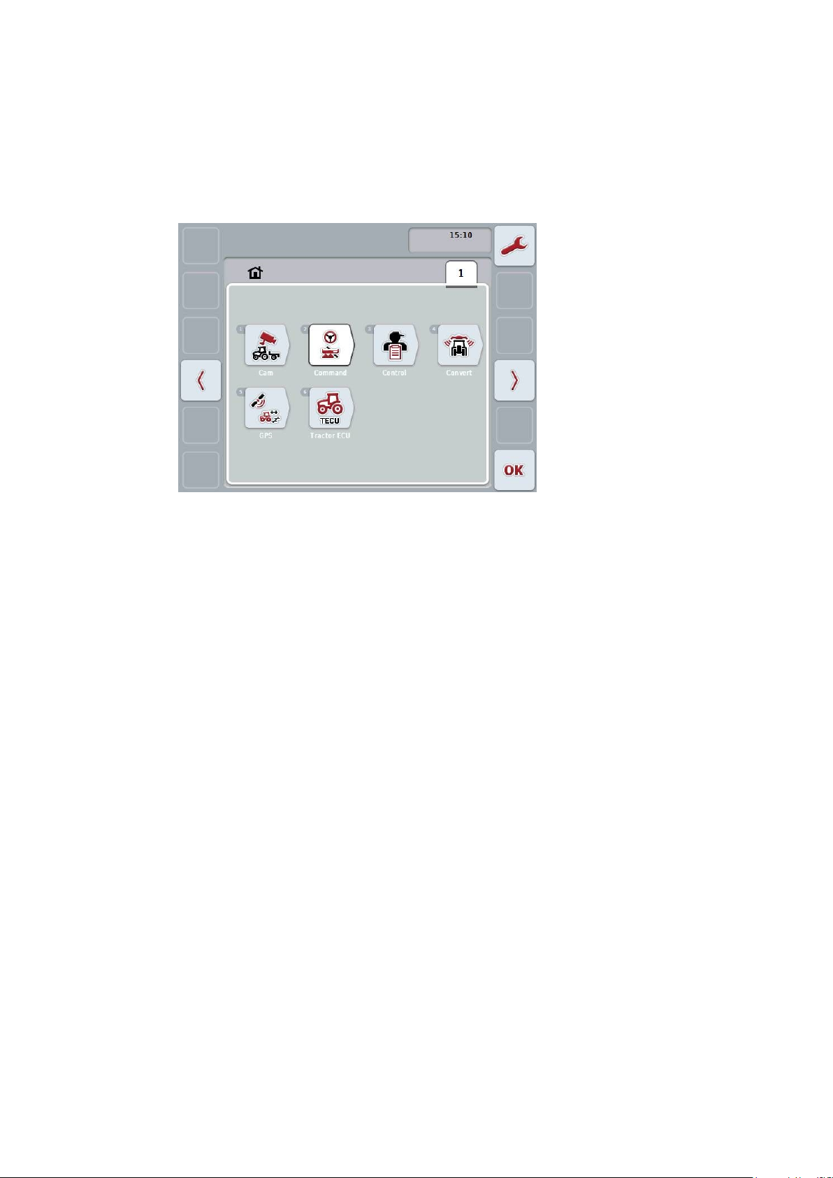
4.3 Main menu
Press the home button.
The Main menu opens:
The main menu displays all the apps and connected ISOBUS implements available to you.
To open an app or an ISOBUS implement press on the symbol in
the icon in the main menu.
To change to the settings press the "Settings" button (F1).
21
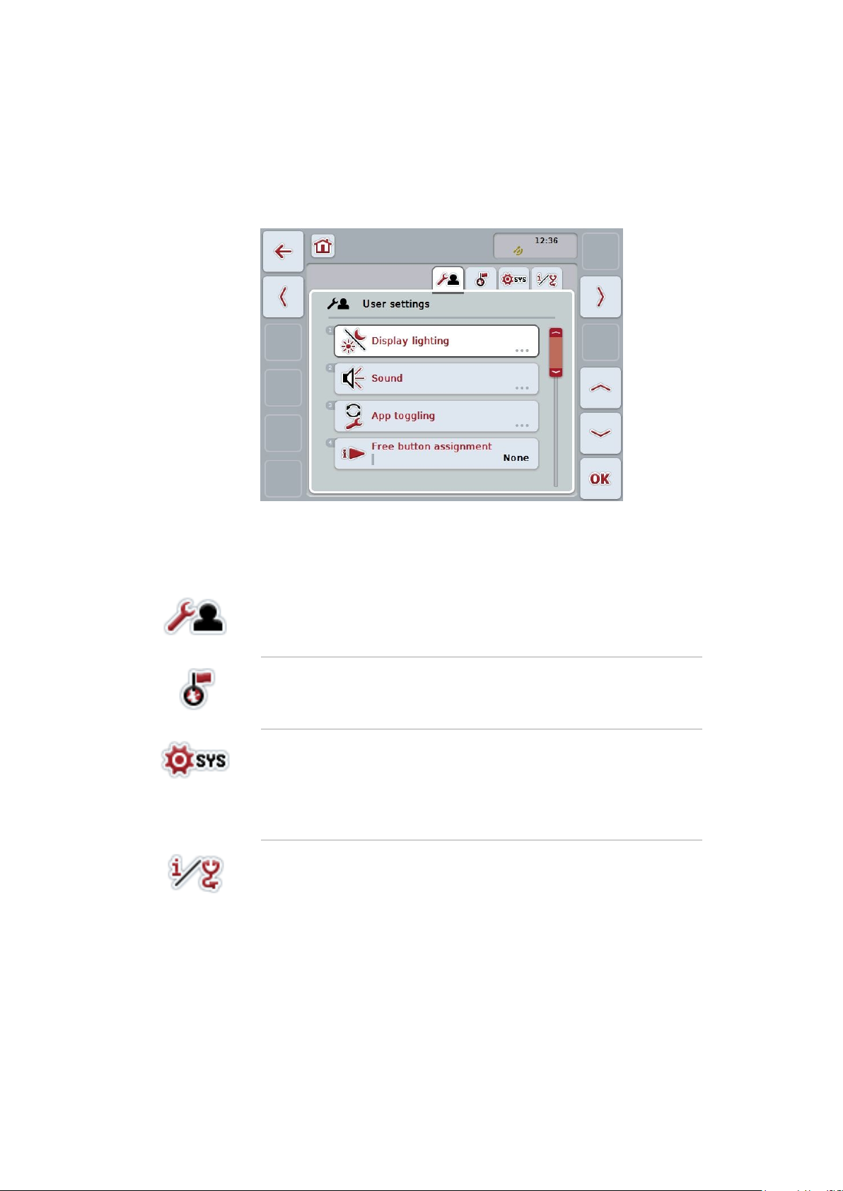
Settings
User settings
Set the display lighting, sound, app toggling, free button as-
signment and the button selection with the scroll wheel.
Country settings
Set the language, keyboard, system of units and decimal sym-
bol.
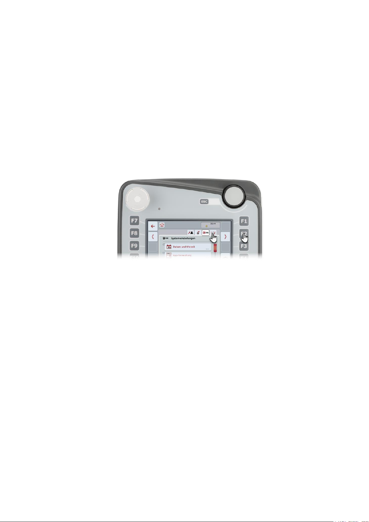
System settings
Set the date and time, app management, CAN, interfaces,
touchscreen calibration.
Access to the service menu.
Entry of licence data.
Info and diagnostics
Display the terminal software and hardware, network mem-
bers, internal memory, RAM and the error memory.
Test the hardware.
5 Settings
The settings are subdivided across 4 tabs: User settings, Country
settings, System settings and Info and Diagnostics.
These are organised as follows:
22
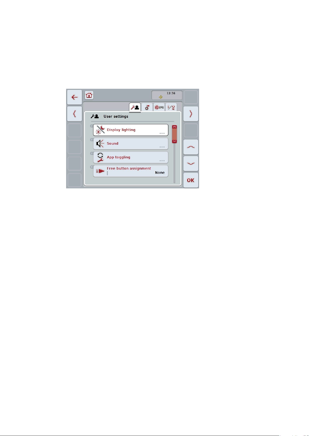
5.1 User settings
The operating characteristics of the terminal are set under the tab
“User settings”.
23
 Loading...