

CC-ISOBUS CCI 100, CCI 200 Operating Instructions Manual
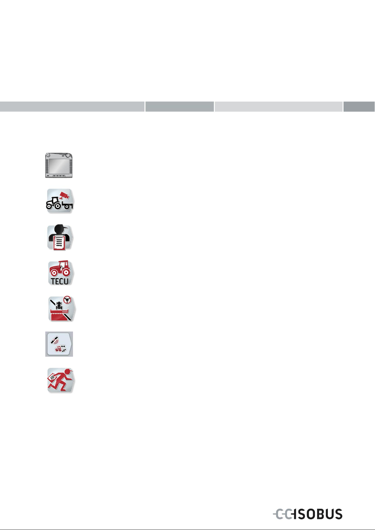
ISOBUS-Terminal CCI 100/200
ISOBUS implement control
CCI.Cam
Visual implement monitoring
CCI.Control
Documentation and task management
CCI.Tecu
Tractor data
CCI.Command
GPS track guiding and section control
CCI.GPS
GPS settings and tractor geometry
CCI.Courier
Task data exchange between farm PC and terminal
Operating Instructions (EN)
Operating instructions
Reference: Firmware v5
ISOBUS
Terminal CCI
100/200
ISOBUS implement control

1 Introduction ............................................................................................................................................. 3
1.1 About the ISOBUS Terminal CCI 100/200 ........................................................................................ 3
2 Safety ....................................................................................................................................................... 4
2.1 Identification of indications in the operating instructions ................................................................... 4
2.2 Intended use ...................................................................................................................................... 5
2.3 Safety indications for the operator / user ........................................................................................... 5
2.4 Safety indications for the installation of electrical devices ................................................................. 6
2.5 Safety indications for the stop switch ................................................................................................ 7
3 Structure and function ........................................................................................................................... 8
3.1 Overview ............................................................................................................................................ 8
3.2 Nameplate.......................................................................................................................................... 8
3.3 Operating elements ........................................................................................................................... 9
3.4 Interfaces ......................................................................................................................................... 13
4 Set-up for operation ............................................................................................................................. 14
4.1 Mounting the terminal ...................................................................................................................... 14
4.2 Connecting the Terminal .................................................................................................................. 15
5 Operation ............................................................................................................................................... 16
5.1 Switching on the terminal ................................................................................................................. 16
5.2 Entering values ................................................................................................................................ 16
5.3 Setting up the terminal ..................................................................................................................... 21
5.4 Creating screenshots ....................................................................................................................... 72
5.5 ISOBUS auxiliary controls (AUX Control) ........................................................................................ 73
6 Troubleshooting ................................................................................................................................... 76
6.1 Terminal errors ................................................................................................................................ 76
6.2 Error messages ............................................................................................................................... 77
6.3 Service ............................................................................................................................................. 78
7 Technical Information .......................................................................................................................... 79
7.1 Mechanical Values ........................................................................................................................... 79
7.2 Electronics ....................................................................................................................................... 79
7.3 Interfaces hardware generation 1 (Version 1.x) .............................................................................. 80
7.4 Interfaces hardware generation 2 (Version 2.x) .............................................................................. 82
8 Menu structure ...................................................................................................................................... 84
9 Glossary ................................................................................................................................................ 85
10 Buttons and icons ................................................................................................................................ 87
11 Index ...................................................................................................................................................... 89
2

ISOBUS Terminal CCI 100/200 – Introduction
CCI.Cam
Visual implement monitoring
CCI.TECU
Tractor data
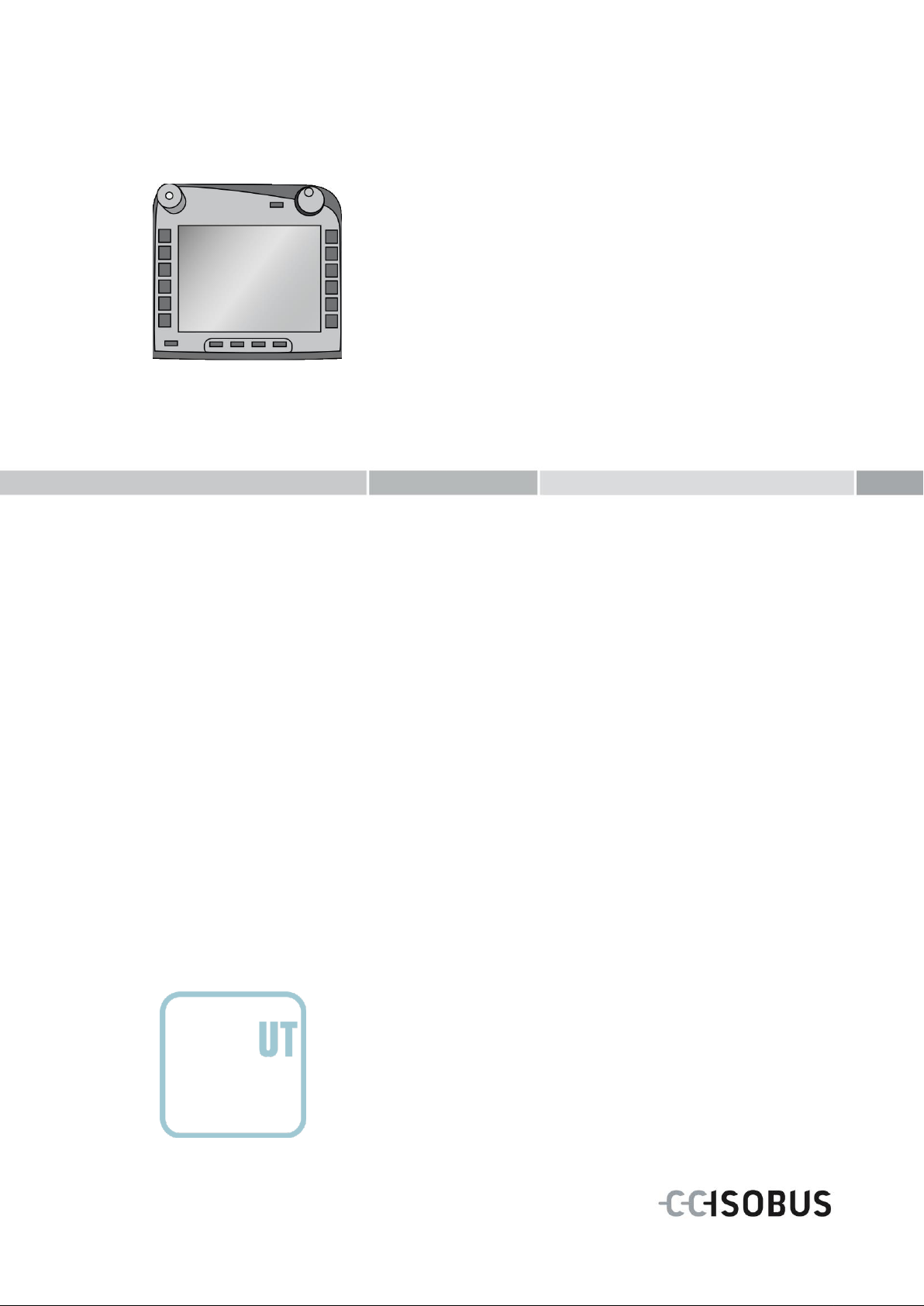
ISOBUS UT
ISOBUS implement operation
CCI.Command
GPS lane guidance and section control
CCI.Control
Documentation and task management
CCI.Convert
Control devices with LH5000, ASD or TUVR
CCI.Courier
Wireless data interchange
CCI.farmpilot
Planning and fleet management
CCI.FieldNav
Agrarian navigation
CCI.File
File Server
CCI.GPS
GPS settings and tractor geometry
DiGIS
Planning and fleet management
Pos: 1 /CC-Isobus/Einleitung @ 9\mod_1 287407057879_6.doc @ 148605 @ @ 1
1 Introduction
These operating instructions are intended as an introduction to the operation and
configuration of the ISOBUS CCI 100/200 Terminal. It is only with knowledge of
these operating instructions that accidental misuse of the terminal can be avoided
and fault-free operation ensured.
These operating instructions must be read and understood prior to assembly and
commissioning of the terminal to prevent problems during operation. No liability is
accepted for damage resulting from the failure to observe these operating
instructions!
1.1 About the ISOBUS Terminal CCI 100/200
CCI 100/200 is a universal terminal and makes possible ISOBUS implement
control.
The following CCI.Apps can be used directly with the CCI 100/200:
The following CCI.Apps can be used on the CCI 100/200 after they are enabled:
3

ISOBUS Terminal CCI 100/200 – Safety
Warning - General Hazards!
This occupational safety symbol identifies general safety indications the nonobservance of which poses a danger for life and limb. Carefully observe the
indications regarding occupational safety and exert particular caution in these
cases.
Caution!
This caution symbol identifies all safety indications referring to regulations,
directives or working procedures which must be observed. Non-observance can
entail damage to, or the destruction of, the terminal as well as malfunctions.
Note
The note symbol highlights operation tips and other particularly useful information.
Pos: 3 /CC-Isobus/Sicherheit @ 9\mod_ 1287407080770_6.doc @ 148700 @ @ 1
2 Safety
These operating instructions contain basic indications which must be observed
during configuration, operation and service. As such, it is absolutely essential to
read these instructions prior to configuration and operation.
Not only do the general safety indications listed in this "Safety" chapter have to be
observed but also the special safety instructions appearing in other chapters as
well.
2.1 Identification of indications in the operating instructions
The safety indications in these operating instructions are specially identified:
4

ISOBUS Terminal CCI 100/200 – Safety
2.2 Intended use
The terminal is exclusively intended for use with approved ISOBUS-compatible
implements and devices in agriculture. Any other installation or use of the terminal
is not included within the manufacturer's area of responsibility.
The manufacturer accepts no liability for any resulting personal injury or material
damage. Any risks for unintended use are borne solely by the user.
Observance of the operation and maintenance conditions stipulated by the
manufacturer also form part of intended use.
The accident prevention regulations in force, as well as other generally recognised
safety, industrial, medical and traffic laws must be observed. Unauthorised
modifications to the device exclude the manufacturer's liability.
2.3 Safety indications for the operator / user
Do not remove any safety mechanisms or signs.
Disconnect the power supply to the terminal during maintenance work or when
using a charging device on the battery of the towed/production implement.
Never perform maintenance work or repairs when the device is switched on.
Disconnect the power supply to the terminal beforehand when welding on the
tractor or an attached implement.
Only use a soft cloth moistened with clean water or a small amount of glass
cleaning agent to clean the terminal.
Use your fingertip to operate the buttons. Avoid using your finger nails.
If, after having read these Operating Instructions, there are sections which you
do not understand contact your dealer for clarification before using the terminal.
Carefully read and observe all safety instructions in the manual and the safety
labels on the device. Safety labels must always be in a proper legible condition.
Replace missing or damaged labels. Ensure that new device parts are provided
with the current safety labels. Spare labels can be obtained from your
authorised dealer.
Learn how to use the terminal in accordance with regulations.
Keep the terminal and accessories in good condition.
5

ISOBUS Terminal CCI 100/200 – Safety
2.4 Safety indications for the installation of electrical devices
Modern farming implements use electronic components and parts the operation of
which can be compromised by electro-magnetic interference from other devices.
Such effects can endanger people if the following safety indications are not
observed.
In the event of retrofitting electric and electronic devices, and/or components, in an
implement with connection to the on-board network, the user must independently
verify whether the installation interferes with vehicle electronics or other
components. This is, in particular, applicable to the electronic interference of:
Electronic hoisting gear control
Front hoisting gear
Power take-off
Engine and gears
It must be ensured in particular that the retrofitted electric and electronic
components comply with the EMC Directive 89/336/EC in its respectively valid
version and that they bear the CE marking.
In order to retrofit mobile communication systems (e.g. radio, telephone), it is
important to meet the following requirements:
Only devices may be installed which are approved in accordance with valid
farming regulations (e.g. BZT (Federal Office for Approval in
Telecommunications) approval in Germany).
The device must be properly installed.
The operation of portable or mobile devices inside the vehicle is only permitted
using a connection to a properly installed external aerial.
The transmitting part must be installed physically and separately from the
vehicle electronics.
When fitting the aerial it must be ensured that the installation is correctly
executed with a good earth connection between the aerial and vehicle earth.
The implement manufacturer's installation instructions must also be used for the
wiring and installation as well as for the maximum permitted power consumption.
6

ISOBUS Terminal CCI 100/200 – Safety
Note
Under no circumstances does the stop switch intervene in tractor functions, i.e.
neither power take off nor hydraulic functions are compromised.
2.5 Safety indications for the stop switch
A safe condition for the connected implement can be established by pressing the
stop switch. In order to do so, the implement must support the stop function.
Further information on this point can be obtained from the implement operating
Pos: 4 /CC-Isobus/**** Seitenumbruch *** * @ 8\mod_1274446340522_0.doc @ 12 1469 @ @ 1
instructions.
7
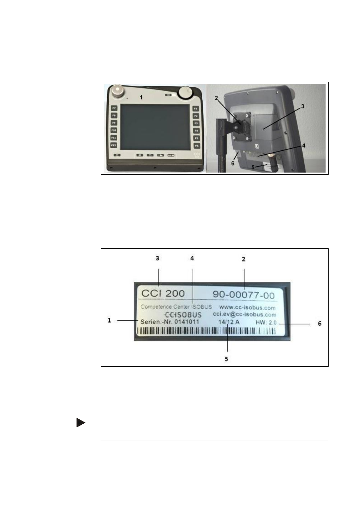
ISOBUS Terminal CCI 100/200 – Structure and function
1 Front view with operating elements
2 Support
3 USB connection (under the flap)
4 Interface strip
5 Nameplate
6 Softkey swap
1 Serial number
2 Manufacturer item number or
material number
3 Terminal type (CCI 100 or 200)
4 Manufacturer information
5 Production date (week and year)
6 Hardware version
Note
The nameplates vary from manufacturer to manufacturer. As such, not all
information is featured on all nameplates.
Pos: 5 /CC-Isobus/Aufbau @ 9\mod_1 287407034989_6.doc @ 148549 @ @ 1
3 Structure and function
3.1 Overview
3.2 Nameplate
The nameplate features all important terminal information.
8
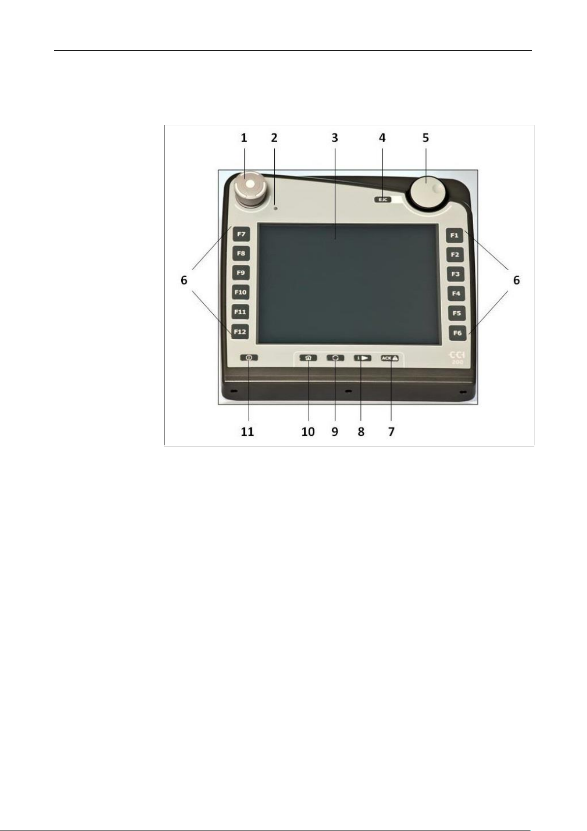
ISOBUS Terminal CCI 100/200 – Structure and function
1 Stop switch
2 Brightness sensor
3 Touchscreen
4 ESC button
5 Scroll wheel
6 Function keys
7 Acknowledgement button
8 i button
9 Toggle button
10 Home button
11 ON/OFF
3.3 Operating elements
The following operating elements are available on the terminal:
9

ISOBUS Terminal CCI 100/200 – Structure and function
Warning – Danger of injury by the implement whilst in operation!
Not all ISOBUS implements support the stop function. As a result, an implement
may continue to operate after the stop switch has been pressed. This can lead to
injuries.
• Please refer to the operating instructions of the implement to verify whether
the function is supported or not.
Note
The ESC button can only be used if there is an ESC button operable via the
touchscreen on the display. The function of button and push button is identical.
Turn the scroll wheel to
the right
• In an input dialogue for numerical values
increases the value.
• In a list changes to the next element.
Turn the scroll wheel to
the left
• In an input dialogue for numerical values
decreases the value.
• In a list changes to the previous element.
Pressing the scroll wheel
• The changed value in an input dialogue is
adopted.
• A highlighted list element is selected.
3.3.1 Stop switch
Upon pressing the Stop switch (designed as an emergency button on the terminal),
a stop command (ISO stop) is sent to the ISOBUS. This command can be
assessed by a connected ISOBUS implement in order to adopt the necessary
automatic measures in a dangerous situation.
3.3.2 ESC button
The ESC button is pressed to abort inputs and functions. The modifications made
are not accepted and the previous valid value is maintained.
3.3.3 Scroll wheel
The scroll wheel is used for the direct, quick input of target values, as well as for
browsing through the elements in the lists:
10

ISOBUS Terminal CCI 100/200 – Structure and function
Note
Swapping of the softkey bar positions is only available in the area of the implement
operation.
Note
With some implements, when changing from an active implement function
operations being performed will automatically switch off. For further information on
this point consult the implement operating instructions.
3.3.4 Function keys
Six function keys (F1-F12) are arranged to the right and left of the display. By
actuating a function key the function displayed next to the function key is
performed.
3.3.5 Softkey swap
The softkey swap is a button on the rear. The positions of both softkey bars on the
left- and right-hand screen edge are swapped over by pressing the softkey swap.
This enables operating the device using one hand.
3.3.6 Acknowledgement button
The acknowledgement button (ACK) is used to confirm error messages.
3.3.7 i button
The i button is a freely assignable button. It makes possible direct access to an app
or device operation that has been selected in the user settings under "Free button
assignment" (see chapter 5.3.3.2).
3.3.8 Toggle button
Repeated quick pressing of the toggle button makes possible sequential toggling
between device operations and the individual apps that have been selected in the
user settings under "App toggling" (see chapter 5.3.3.1) for example from device
operation to CCI.TECU.
11

ISOBUS Terminal CCI 100/200 – Structure and function
Note
With some implements, when changing from an active implement function
operations being performed will automatically switch off. For further information on
this point consult the implement operating instructions.
3.3.9 Home button
By pressing the home button you change directly to the main menu. The apps
which are active at the time of changing remain active in the background.
3.3.10 Touchscreen
The terminal is equipped with a top-quality touchscreen for menu navigation and
the easy input of values and texts. By touching the screen functions can be
requested directly and values changed.
12
ISOBUS Terminal CCI 100/200 – Structure and function
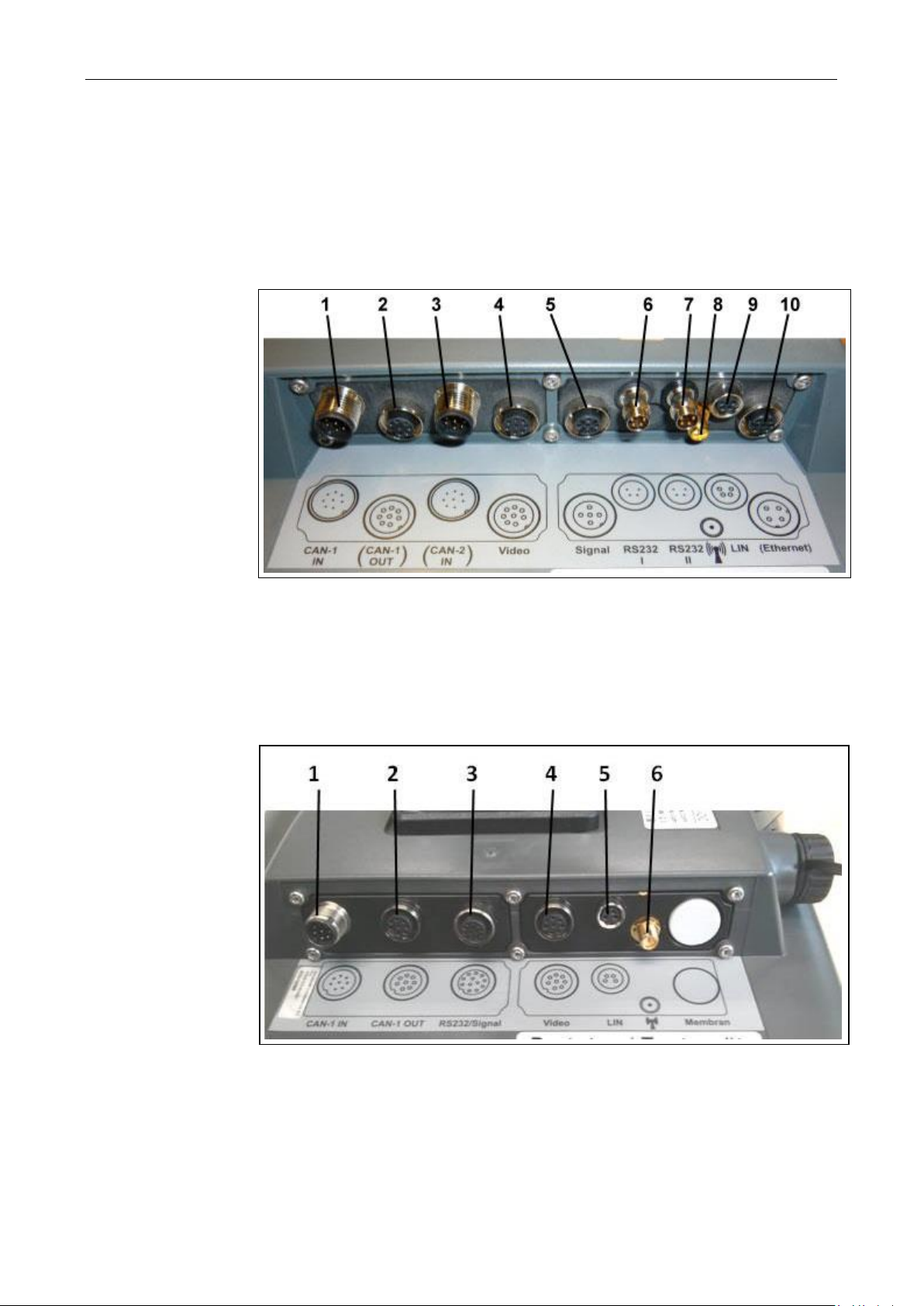
1 CAN1-IN
2 CAN1-OUT
3 CAN2-IN (only CCI 200)
4 Video-IN
5 Signal (ISO 11786)
6 RS232-1
7 RS232-2
8 Wi-Fi (only CCI 200)
9 LIN
10 ETHERNET (only CCI 200)
1 CAN1-IN
2 CAN1-OUT
3 Signal (ISO11786) +
RS232-1
RS232-2
4 Video-IN
5 LIN
6 Wi-Fi
3.4 Interfaces
The interface bar is on the rear of the terminal. Additionally the terminal's USB
connection can be found on the rear side under a flap (hardware generation 1) or a
round cap (hardware generation 2 and 3). For a detailed description of the USB
connection, see chapter 5.4.
Hardware generation 1:
Hardware generation 2 and 3:
13

ISOBUS Terminal CCI 100/200 – Set-up for operation
1. 2.
3. 4.
5. 6.
Note
Ensure that the screws are tightened firmly.
Secure the terminal so that it can be read and operated easily and so that it does
not hinder access to the operating elements of the tractor or block the view outside.
Pos: 7 /CC-Isobus/Installation @ 9\mod _1287407065114_6.doc @ 148633 @ @ 1
4 Set-up for operation
4.1 Mounting the terminal
The device support for fixing the terminal to the tractor cab is included in the scope
of delivery.
Proceed as follows to mount the terminal in the cab:
1. Assemble the device support (Figures 1 and 2).
2. Mount the device support to the frame and to the terminal (Figures 3 and 4).
3. Select a suitable position in the tractor cab (within the driver's field of vision)
for fitting the terminal (Figures 5 and 6).
4. Secure the terminal with the device support in the tractor cab.
14
ISOBUS Terminal CCI 100/200 – Set-up for operation
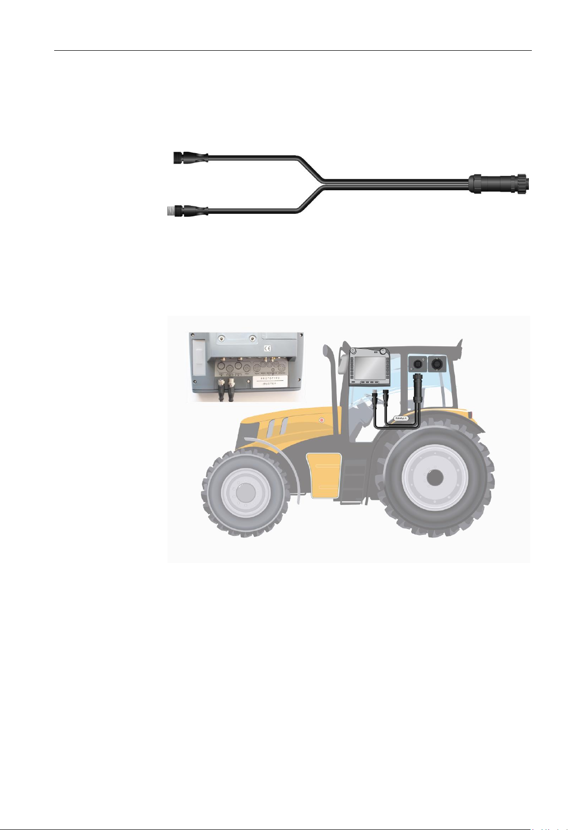
4.2 Connecting the Terminal
4.2.1 Connecting to ISOBUS/power supply
For connection to ISOBUS and power supply the type A cable is necessary.
Cable type A
Proceed as follows to connect the terminal to the ISOBUS and the power supply:
1. Connect the "CAN1-IN" and "CAN1OUT" interfaces on the terminal using the
type A cable to the In-cab socket of the tractor.
Pos: 8 /CC-Isobus/**** Seitenumbruch *** * @ 8\mod_1274446340522_0.doc @ 12 1469 @ @ 1
15
ISOBUS Terminal CCI 100/200 – Operation
Note
Before switching on the terminal for the first time, check that the connections on
the device are properly and correctly positioned.
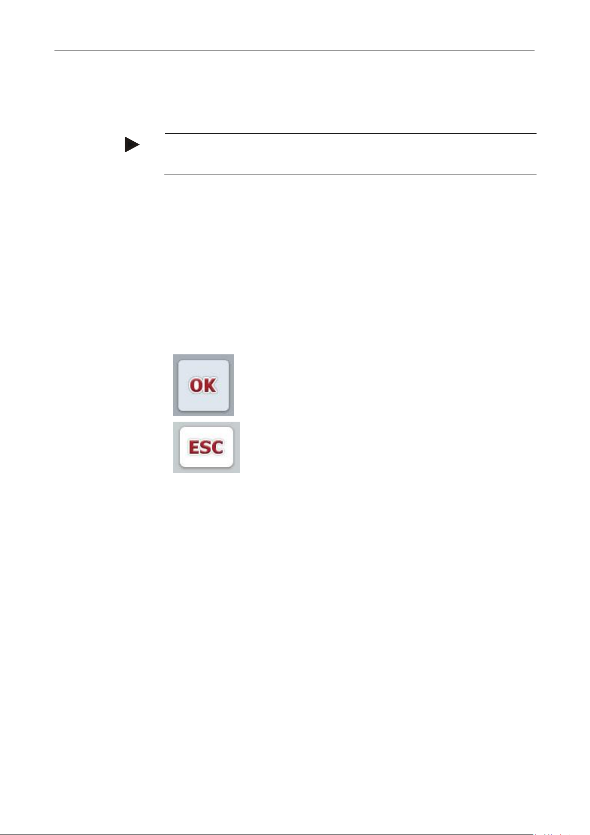
By using the "OK" button, the newly set target value is accepted
in all input dialogues. The previous value is overwritten.
Alternatively, the scroll wheel can be pressed to accept the new
value.
By using the "ESC" button, the input is aborted in all input
dialogues. The previous value is maintained.
Alternatively, the "ESC" button can be pressed on the scroll
wheel to abort the action.
Pos: 9 /CC-Isobus/Bedienung @ 9\mod _1287407049442_6.doc @ 148577 @ @ 1
5 Operation
5.1 Switching on the terminal
1. Switch on the terminal using the "ON/OFF" button on the casing at the bottom
left. Press the button for approx. 2 seconds.
5.2 Entering values
Values must be entered, changed or selected for the configuration and use of both
the terminal and the connected ISOBUS implements.
The values are modified by using the so-called input dialogues. These dialogues
are shown above the current active operating screen. After modification the input
dialogue is closed and the user returns to the operating screen.
5.2.1 Buttons in Input Dialogues
16
ISOBUS Terminal CCI 100/200 – Operation
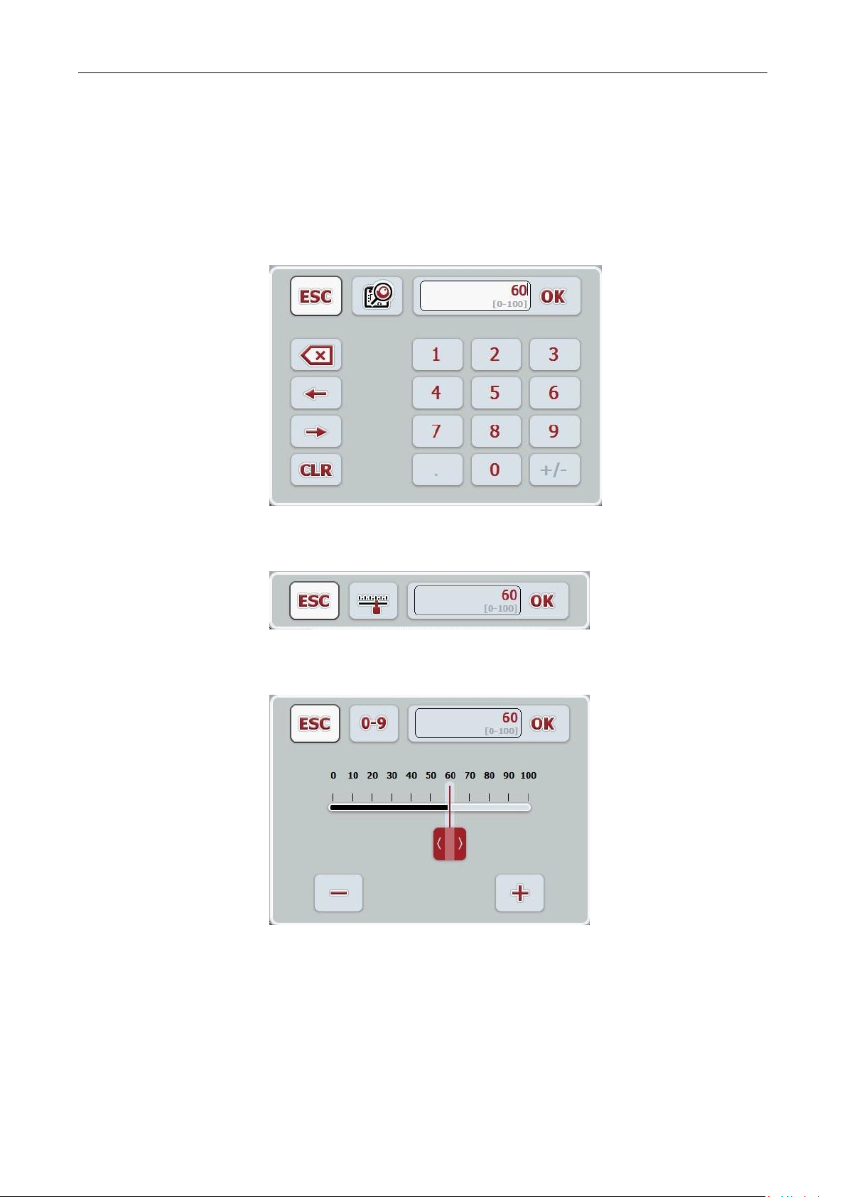
5.2.2 Entering numerical values
If a parameter is selected from an operating screen which has a numerical value,
the input dialogue for numerical values appears. There are three different dialogue
formats:
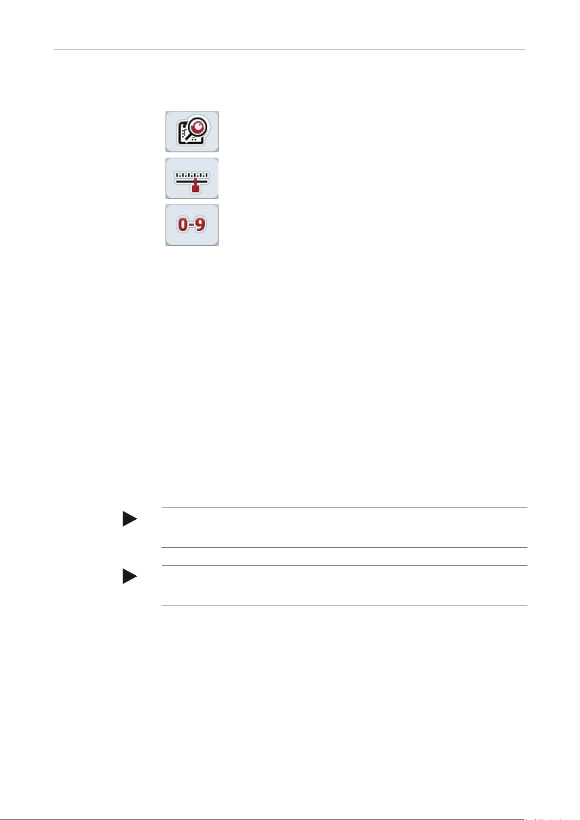
1. Number Block
2. Scroll wheel
3. Slider
17
ISOBUS Terminal CCI 100/200 – Operation
Change to scroll wheel setting.
Change to slider setting.
Change to number block setting.
Number Block
Enter the value using the buttons in the input dialogue or
by turning the scroll wheel.
Scroll wheel
Enter the value by turning the scroll wheel.
Slider
Drag the slider or press the "+" and "-" buttons until the
desired value is set.
Alternatively you can also enter the value by turning the
scroll wheel.
Note
The terminal takes note of the last format to be selected. The next time the input
dialogue for numerical values is requested this format is immediately selected.
Note
The input field is highlighted in red if a value is entered outside the valid value
range. In this case enter another value.
The following buttons can be used to change between the various formats of the
input dialogue for numerical values:
Proceed as follows to enter a numerical value:
1. In the operating screen, select the parameter for which the value needs to be
changed. Press on the parameter on the touchscreen or turn the scroll wheel
until the parameter is highlighted in white and then press on the scroll wheel.
Once the parameter is highlighted, alternatively you can also press the "OK"
button.
→ The input dialogue is opened.
2. Enter the new value. The input method depends on the format of the input
dialogue:
3. Confirm your input with "OK" or by pressing the scroll wheel.
18
ISOBUS Terminal CCI 100/200 – Operation
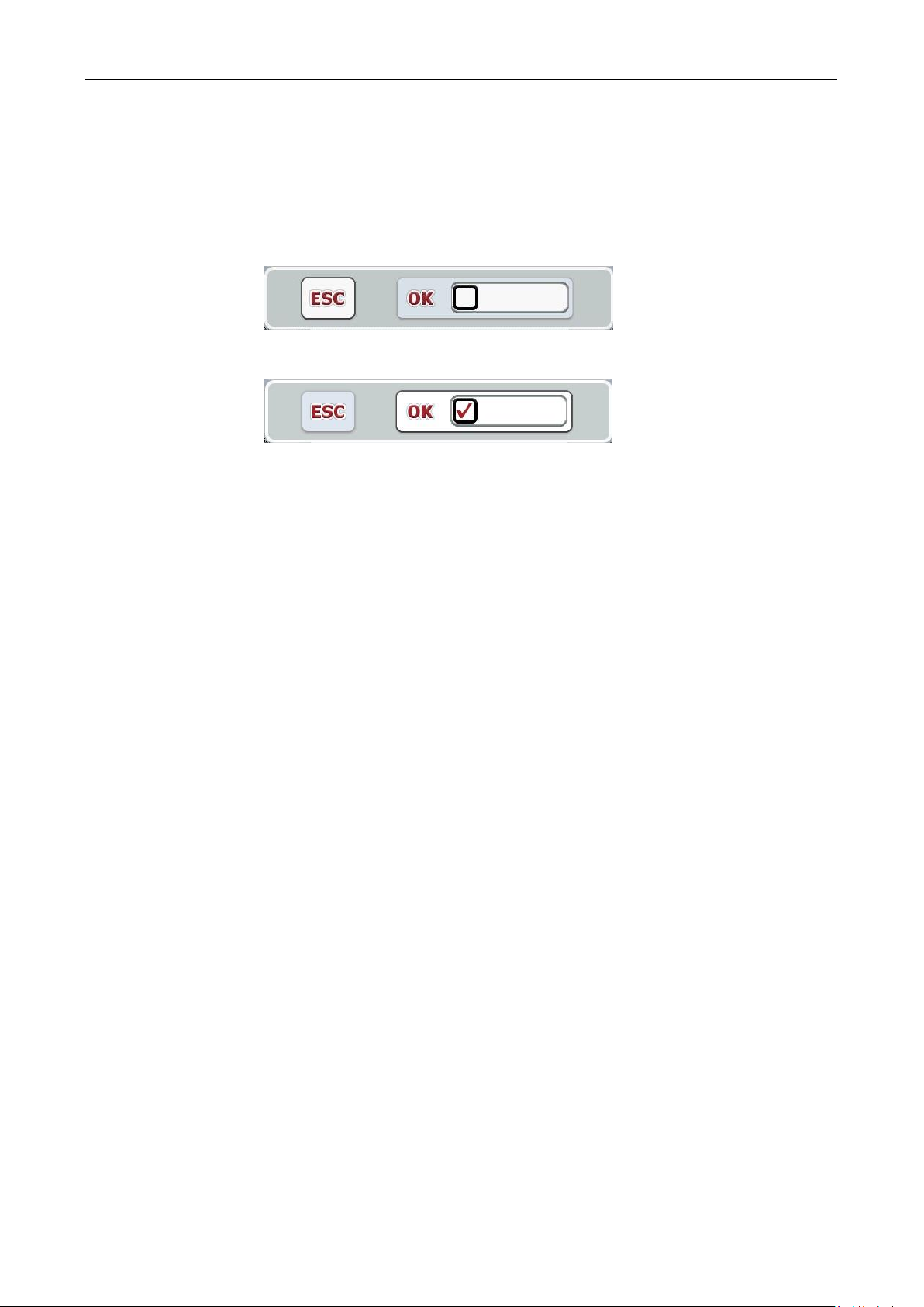
5.2.3 Entering Boolean Values
A Boolean value is a value whereby it is only possible to choose between
true/false, on/off, yes/no etc. If a parameter is selected in an operating screen
which has a Boolean value, the corresponding input dialogue appears.
Display for false, off, no:
Display for true, on, yes:
Proceed as follows to enter a Boolean value:
1. In the operating screen select the parameter for which the value needs to be
changed. Press on the parameter on the touchscreen or turn the scroll wheel
until the parameter is highlighted in white and then press on the scroll wheel.
Once the parameter is highlighted, alternatively you can also press the "OK"
button.
→ The input dialogue is opened.
2. Enter the new value. Press the square with the black border in the input field.
Alternatively you can also change the value by turning the scroll wheel.
3. Confirm your input with "OK" or by pressing the scroll wheel.
19
ISOBUS Terminal CCI 100/200 – Operation
Note
You can minimise the displayed list by pressing the input field (between "ESC" and
"OK"). The input dialogue for the list selection is then shown with a minimised list.
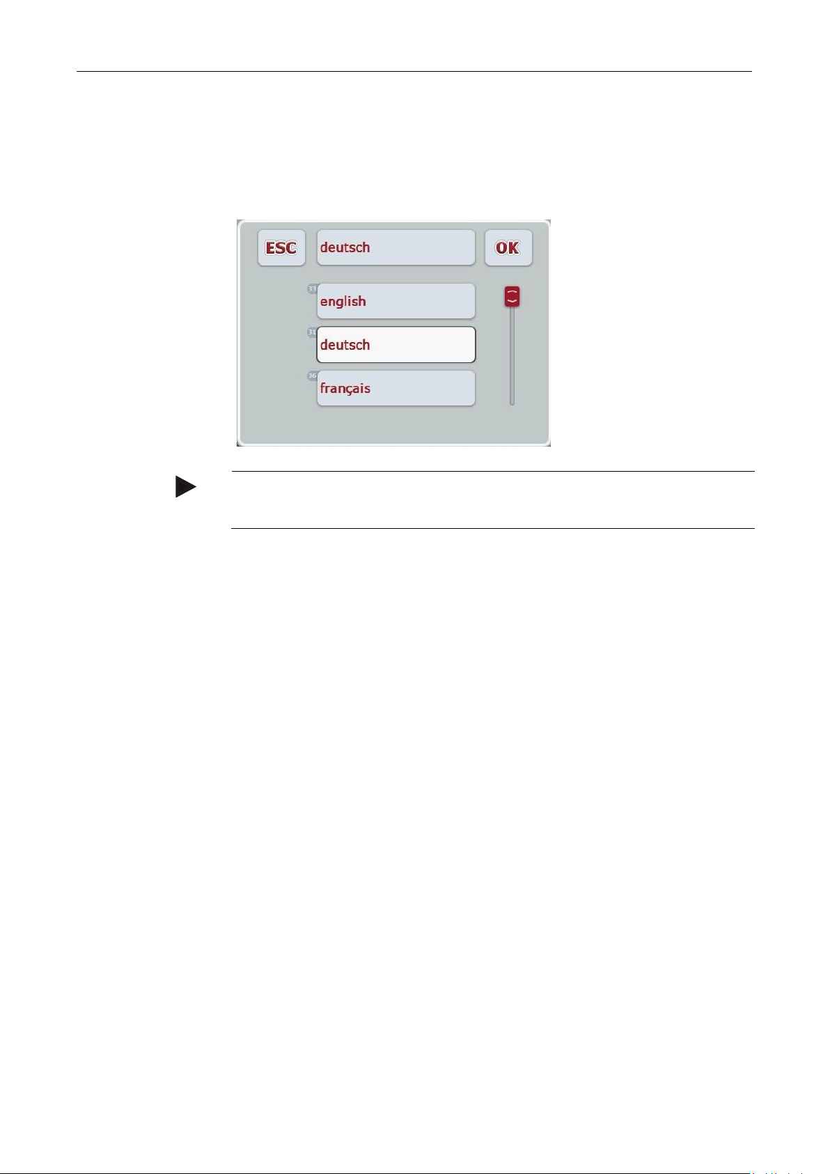
5.2.4 Selecting values from a list
For specific parameters there are lists of default values, e.g. the language setting.
If such a parameter is selected from an operating screen the input dialogue for the
list selection appears.
Proceed as follows to enter a value from a list:
1. In the operating screen select the parameter for which the value needs to be
changed. Press on the parameter on the touchscreen or turn the scroll wheel
until the parameter is highlighted in white and then press on the scroll wheel.
Once the parameter is highlighted, alternatively you can also press the "OK"
button.
→ A selection list opens.
2. Select the new value from the list. To do so press the button with the value or
turn the scroll wheel until the button is highlighted in white and then press on
the scroll wheel.
→ The value appears in the selection window.
3. Confirm your selection by pressing "OK" or pressing the button with the value
again or by pressing the scroll wheel.
20
ISOBUS Terminal CCI 100/200 – Operation
Note
A detailed description of the settings of a connected ISOBUS implement can be
referred to in the operating instructions of the relevant implement.
From each submenu (and their menu items) you can return to the
Main Menu directly by pressing this button, which is located on
the top screen edge.
5.3 Setting up the terminal
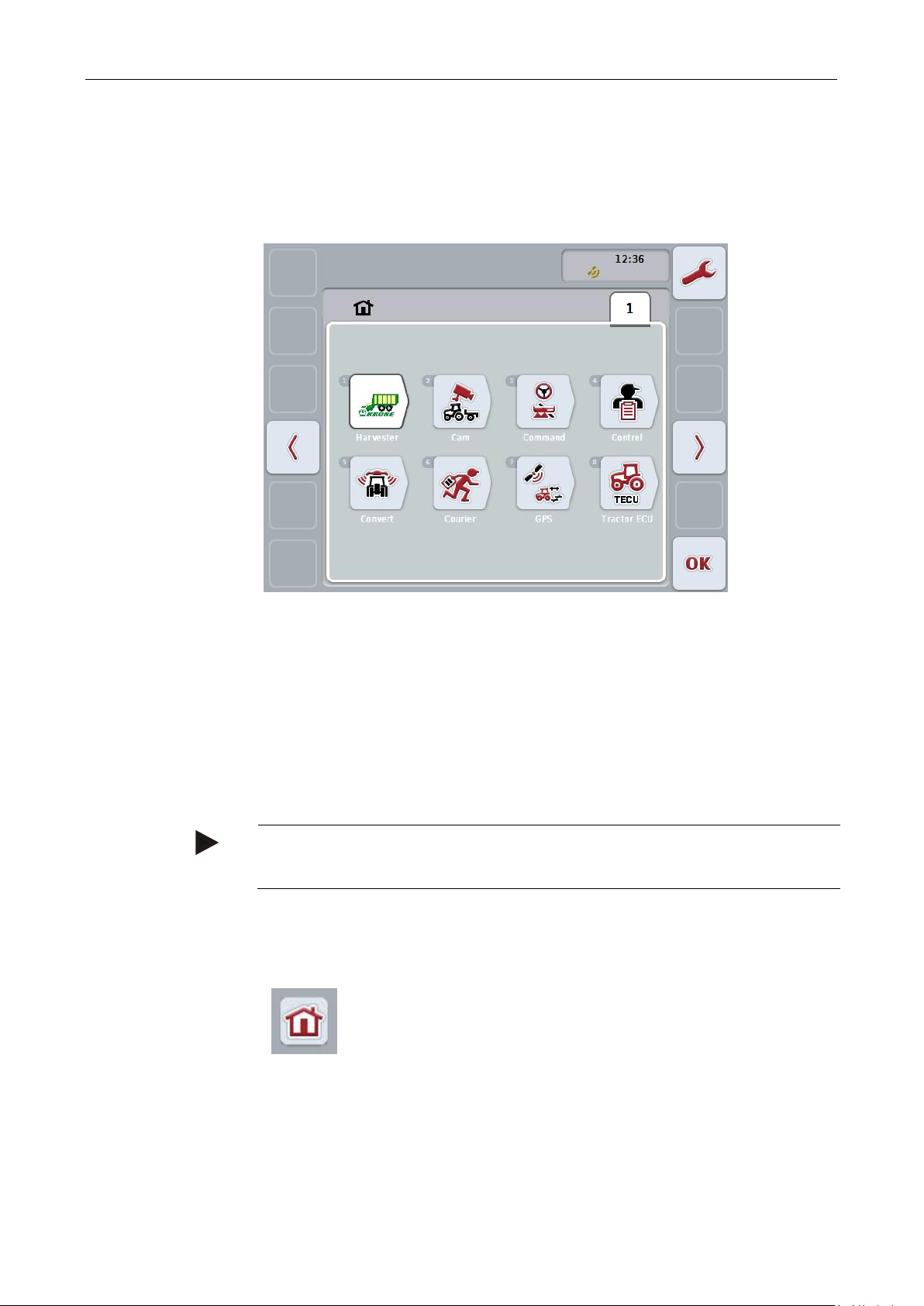
5.3.1 Main menu
Open the main menu:
All available apps are shown in the Main menu. These are the apps that are
enabled on the terminal, e.g. CCI.TECU and CCI.Cam and the operating images of
the connected implements.
1. To call up an application, on the touchscreen press on the operating image of
the implement or the app's symbol.
Once the button is highlighted white you can alternatively also press the scroll
wheel or the "OK" (F6) button.
You can directly access the settings (F1) from the Main Menu.
In the following sections the settings are described in detail. A graphic depiction of
the complete menu structure can be referred to in the chapter 8.
21
ISOBUS Terminal CCI 100/200 – Operation
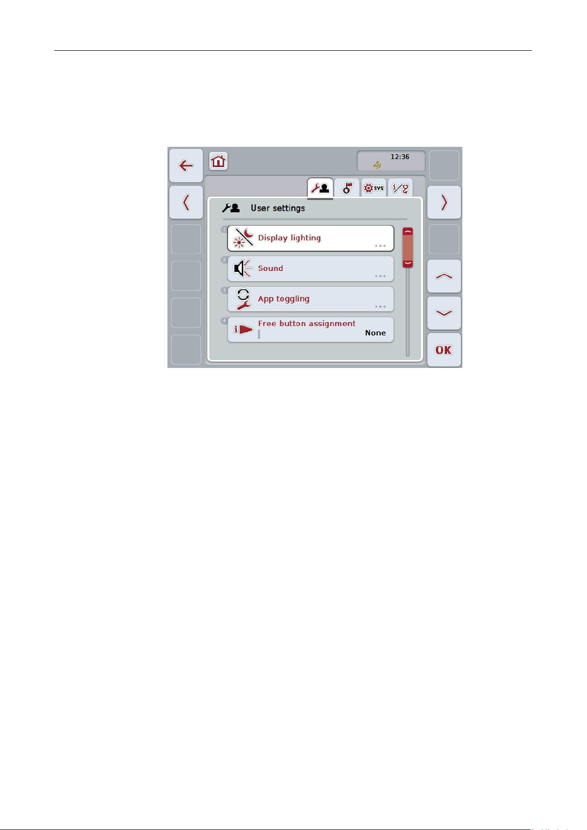
User settings:
Offers adjustment options for the display lighting,
sound, app toggling, free button assignment and the
button selection with the scroll wheel.
Country settings:
Offers setting options for language, keyboard,
system of units, and decimal symbol.
System settings:
Offers setting options for date and time, app
management, CAN, interfaces , calibration of the
touchscreen and access to the service menu.
Info and Diagnostics:
Provides information about the software and
hardware of the terminal, about the network
members, the internal, RAM and error memory.
Makes it possible to test the various hardware
components.
5.3.2 Settings
The settings are subdivided across 4 tabs: User settings, Country settings,
System settings and Info and Diagnostics.
These are organised as follows:
To switch between tabs, proceed as follows:
1. Press the corresponding tab on the touchscreen or select it using the arrow
keys (F8, F2).
22

ISOBUS Terminal CCI 100/200 – Operation
Change to Display lighting
Press the "Display lighting" button on the touchscreen.
The Display lighting screen opens.
More detailed information on Display lighting can be consulted in
chapter 5.3.3.4.
To change the sound
Press the "Sound" button on the touchscreen.
The Sound screen opens.
More detailed information on sound can be consulted in chapter
5.3.3.5.
App toggling
Free button assignment
Activate/deactivate button selection by scroll wheel
5.3.3 User settings
In the User Settings tab it is possible to adjust the terminal to match your personal
requirements.
You have the following operating options:
23

ISOBUS Terminal CCI 100/200 – Operation
Note
This setting only acts on implement operation.
5.3.3.1 App toggling
Proceed as follows to specify the apps between which it will be possible to switch
by pressing the toggle button:
1. Press on the button of the app in question on the touchscreen or turn the scroll
wheel until the button is highlighted in white and then press on the scroll
wheel.
2. Once the button is highlighted you can, alternatively, also press the "OK" (F6)
button.
3. Enter the Boolean value.
4. Confirm your entry with "OK".
5.3.3.2 Free button assignment
A choice of free button assignment can be made so that it is possible to choose
which app you can access directly via the i button.
To assign the i button, proceed as follows:
1. Press on the "Free button assignment" button on the touchscreen or turn the
scroll wheel until the button is highlighted in white and then press on the scroll
wheel.
Once the button is highlighted you can, alternatively, also press the "OK" (F6)
button.
→ A selection list opens.
2. Select the desired setting from the list. To do so press the button with the app
or turn the scroll wheel until the button is highlighted in white and then press
on the scroll wheel.
→ The app appears in the selection window.
3. Confirm your selection by pressing "OK" or pressing the button with the app
again or by pressing the scroll wheel.
5.3.3.3 Activate/deactivate button selection by scroll wheel
To activate/deactivate button selection by scroll wheel, proceed as follows:
1. Press on the "Button selection by scroll wheel" button on the touchscreen or
turn the scroll wheel until the button is highlighted in white and then press on
the scroll wheel.
Once the button is highlighted you can, alternatively, also press the "OK" (F6)
button.
2. Enter the Boolean value.
3. Confirm your entry with "OK".
24
ISOBUS Terminal CCI 100/200 – Operation
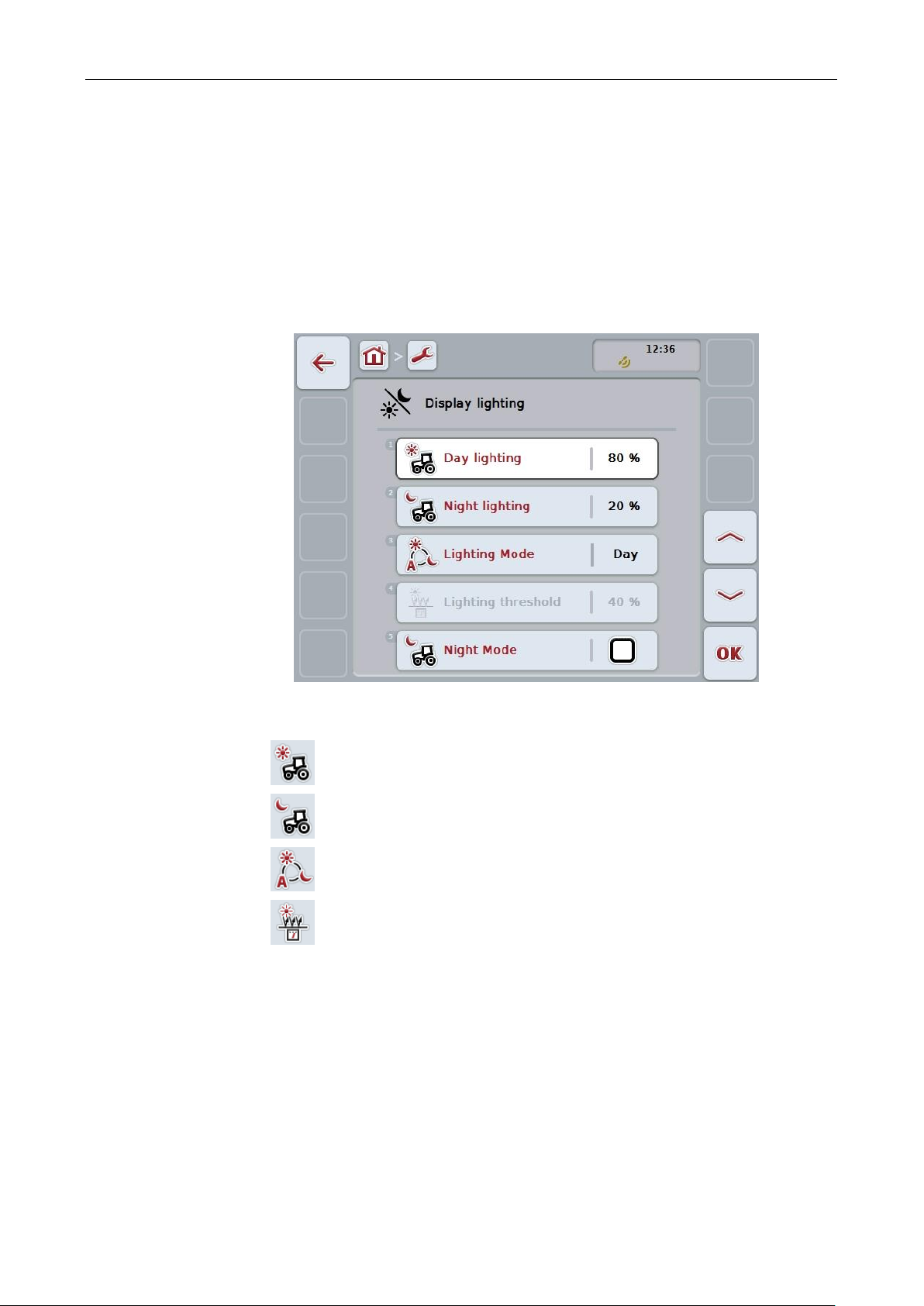
Enter Day lighting
Enter Night lighting
Select Lighting Mode
Enter Lighting threshold
5.3.3.4 Display lighting
To change to the Display lighting settings proceed as follows:
1. Press on the "Display lighting" button on the touchscreen or turn the scroll
wheel until the button is highlighted in white and then press on the scroll
wheel.
Once the button is highlighted you can, alternatively, also press the "OK" (F6)
button.
→ The following screen opens:
You have the following operating options:
25

ISOBUS Terminal CCI 100/200 – Operation
Note
The value for the Display lighting is given as a percentage and can be adjusted in
steps of 10%.
Note
The value for the Display lighting is given as a percentage and can be adjusted in
steps of 10%.
5.3.3.4.1 Enter Day lighting
To enter the desired display brightness for daytime operation, proceed as follows:
1. Press on the "Day lighting" button on the touchscreen or turn the scroll wheel
until the button is highlighted in white and then press on the scroll wheel.
Once the button is highlighted you can, alternatively, also press the "OK" (F6)
button.
2. Enter the value on the touchscreen using the number pad or the slider.
3. Confirm your entry with "OK".
5.3.3.4.2 Enter Night lighting
To enter the desired display brightness for night-time operation, proceed as
follows:
1. Press on the "Night lighting" button on the touchscreen or turn the scroll wheel
until the button is highlighted in white and then press on the scroll wheel.
Once the button is highlighted you can, alternatively, also press the "OK" (F6)
button.
2. Enter the value on the touchscreen using the number pad or the slider.
3. Confirm your entry with "OK".
26

ISOBUS Terminal CCI 100/200 – Operation
Note
The value for the Display lighting is given as a percentage and can be adjusted in
steps of 10%.
5.3.3.4.3 Select Lighting Mode
To select a Lighting Mode mode proceed as follows:
1. Press on the "Lighting Mode" button on the touchscreen or turn the scroll
wheel until the button is highlighted in white and then press on the scroll
wheel.
Once the button is highlighted you can, alternatively, also press the "OK" (F6)
button.
→ A selection list opens.
2. Select the desired setting from the list. To do so press the button with the
Lighting Mode or turn the scroll wheel until the button is highlighted in white
and then press on the scroll wheel.
→ The Lighting Mode appears in the selection window.
3. Confirm your selection by pressing "OK" or pressing the button with the
lighting mode again or by pressing the scroll wheel.
5.3.3.4.4 Enter Lighting threshold
An on/off point is specified for the display lighting. The value provided by the
brightness sensor is the reference variable.
The illumination is activated when exceeding the ON activation point and
deactivated when undershooting the OFF activation point.
Proceed as follows to enter the lighting threshold:
1. Press on the "Lighting threshold" button on the touchscreen or turn the scroll
wheel until the button is highlighted in white and then press on the scroll
wheel.
Once the button is highlighted you can, alternatively, also press the "OK" (F6)
button.
2. Enter the value on the touchscreen using the number pad or the slider.
3. Confirm your entry with "OK".
27
ISOBUS Terminal CCI 100/200 – Operation
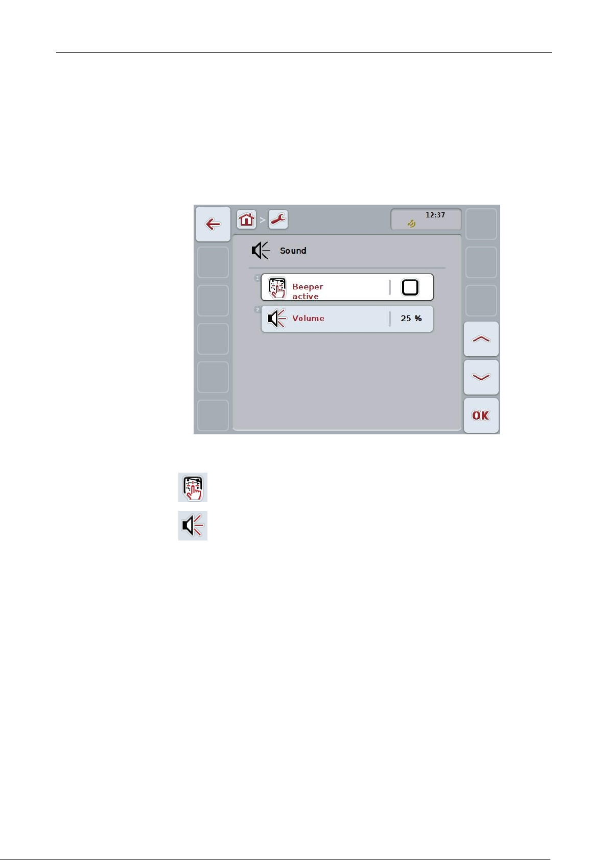
Activate/deactivate beeper
Enter volume
5.3.3.5 Sound
To change Sound settings proceed as follows:
1. Press on the "Sound" button on the touchscreen or turn the scroll wheel until
the button is highlighted in white and then press on the scroll wheel.
Once the button is highlighted you can, alternatively, also press the "OK" (F6)
button.
→ The following screen opens:
You have the following operating options:
28

ISOBUS Terminal CCI 100/200 – Operation
Note
The value for the volume is given as a percentage and can be adjusted in steps of
5% in the range 25% to 100%.
5.3.3.5.1 Activate/deactivate beeper
If the beeper is active, then you receive an acoustic acknowledgement upon
touching a button in the touchscreen or one of the function keys.
To activate/deactivate the beeper, proceed as follows:
1. Press on the "Beeper active" button on the touchscreen or turn the scroll
wheel until the button is highlighted in white and then press on the scroll
wheel.
Once the button is highlighted you can, alternatively, also press the "OK" (F6)
button.
2. Enter the Boolean value.
3. Confirm your entry with "OK".
5.3.3.5.2 Enter volume
To enter the beeper volume, proceed as follows:
1. Press on the "Volume" button on the touchscreen or turn the scroll wheel until
the button is highlighted in white and then press on the scroll wheel.
Once the button is highlighted you can, alternatively, also press the "OK" (F6)
button.
2. Enter the value on the touchscreen using the number pad or the slider.
3. Confirm your entry with "OK".
29
 Loading...