

Page 1

MANUAL TÉCNICO
VCR-505
Page 2
2
1. Before returning the instrument to the customer always make
a safety check of the entire instrument including but not limited
to the following items.
a. Be sure that no built-in protective devices are defective
and/or have been defeated during servicing (1) Protective
shields are provided on this instrument to protect both the
technician and the customer. Correctly replace all missing
protective shields. including any removed for servicing convenience. (2) When reassembling the instrument be sure to
put back in place all protective device including but not limited to nonmetallic control knobs insulating fishpapers
adjustment and compartment covers/shields and isolation
resistor capacitor networks. Do not operate this instru-
ment or permit it to be operated without all protective
devices correctly installed and functioning. Servicers
who defeat safety features or fail to perform safety
checks may be liable for any resulting damage, and may
expose themselves and others to possible injury.
b. Be sure that there are no cabinet openings through which an
adult or child might be able to insert their fingers and contact a hazardous voltage. Such openings include but are not
limited to (1) excessively wide cabinet ventilation slots and
(2) improperly fitted and/or incorrectly secured cabinet covers.
c. Leakage Cold Check – With the instrument AC plug
removed from any AC source, connect an electrical jumper
across the two AC plug prongs. Place the instrument AC
switch in the on position. Connect one lead of an ohmmeter
to the AC plug prongs tied together and touch the other
ohmmeter lead in turn to each push button/customer control
exposed metal screws, metalized overlays and to each
cable connector. If the measured resistance is less than 1.0
megohm or greater than 5.2 megohm an abnormality exists
that must be corrected before the instrument is returned to
the customer. Repeat this test with the AC switch in the off
position.
AC Leakage Test
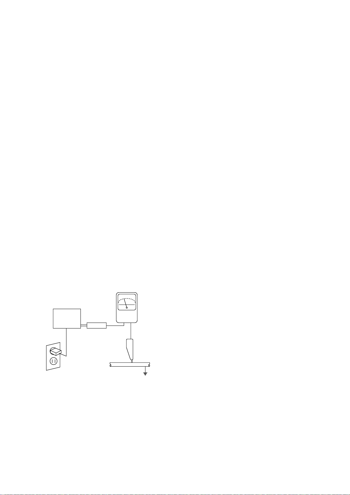
d. Leakage Current Hot Check
On completely assembled instrument, plug the AC line cord
directly into a 120V AC outlet. (Do not use an isolation transformer during this test). Use a leakage current tester or a
metering system that complies with American National
Standards Institute (ANSI) C101.1 Leakage Current for
Appliances and Underwriters Laboratories (UL) 1410, (59.7).
Measure for current from a known earth ground (metal
waterpipe, conduit, etc.) to all exposed metal or conductive
parts of the instrument (antenna connections, handle bracket, metal cabinet, screwheads, metallic overlays, push-buttons, control shafts, etc.) especially any exposed metal parts
that ofter an electrical return path to the chassis. Any current
measured must not exceed 0.5 milliamp. Reverse the instrument power cord plug in the outlet and repeat the test.
ANY MEASUREMENTS NOT WITHIN THE LIMITS SPECIFIED HEREIN INDICATE A POTENTIAL SHOCK HAZARD
THAT MUST BE ELIMINATED BEFORE RETURNING THE
INSTRUMENT TO THE CUSTOMER OR BEFORE CONNECTING TO ANTENNA OR ACCESSORIES.
e. Interconnected Equipment AC Leakage Test
Avoid shock hazards The instrument, accessory or cable(s)
to which this instrument is connected should have the
applicable sections of the leakage resistance cold check
and the leakage current hot check performed Do not connect this instrument to an antenna cable or accessory that
exhibits excessive leakage currents.
2. Read and comply with all caution and safety-related notes on or
inside the instrument cabinet and on the chassis.
3. Design Alteration Warning – Do not alter or add to the mechan-
ical or electrical design of this instrument. Design alterations
and additions, including, but not limited to circuit modifications
and the addition of items such as auxiliary audio output connections cables and accessories etc might alter the safety characteristics of this instrument and create a hazard to the user
Any design alterations or additions will void the manufacturer's
warranty and will make you the servicer responsible for personal injury or property damage resulting therefrom.
4. Observe original lead dress Take extra care to assure correct
lead dress in the following areas a near sharp edges b near
thermally hot parts – be sure that leads and components do not
touch thermally hot parts and c the AC supply Always inspect in
all areas for pinched out-of-place or frayed wiring Do not
change spacing between components and between components and the printed-circuit board Check AC power cord for
damage.
5. Components parts and/or wiring that appear to have overheated
or are otherwise damaged should be replaced with components, parts, or wiring that meet original specifications.
Additionally determine the cause of overheating and/or damage
and if necessary take corrective action to remove any potential
safety hazard.
6. PRODUCT SAFETY NOTICE – Many electrical and mechanical
parts have special safety-related characteristics some of which
are often not evident from visual inspection nor can the protection they give necessarily be obtained by replacing them with
components rated for higher voltage, wattage, etc. Parts that
have special safety characteristics are identified in this service
data by a star (¡ ) on schematics and a (¡ ) in the parts list. Use
of a substitute replacement that does not have the same safety
characteristics as the recommended replacement part in this
service data parts list might create shock, fire, and/or other
hazards. Product Safety is under review continuously and new
instructions are issued whenever appropriate. For the latest
information, always consult the appropriate current service literature.
DEVICE
UNDER
TEST
TEAKAGE
CURRENT
TESTER
TEST ALL
EXPOSED METAL
SURFACES
2WIRE CORD
ALSO TEST WITH
PLUG REVERSED
DSING AC ADAPTER
PCUG AS REOUIRED
EARTH
GROUND
READING SHOULD
NOT BE ABOVE
0.5mA
SAFETY PRECAUTIONS
Page 3

3
Power Input: 90~260 Volts AC 60Hz
Power Consumption: 14 Watts (4-head Hi-Fi)
13 Watts (4-head)
Operating Temperature: 5 degree C to 35 degree C
(41 degree F to 95 degree F)
Storage Temperature: -20 degree C to 60 degree C
(-4 degree F to 140 degree F)
Weight: 5.5 kg
Dimensions: 360mm Wide X 90mm High X
312mm Deep
Recording System:
4-head Hi Fi: Four video record/playback
heads
Rotary helical scan/luma: FM
recording/chroma: down
converted
subcarrier phase shifted
recording
Two audio record/playback
heads
Rotary helical scan, 2 channels
FM recording
4-head: Four video record/playback
heads
Rotary helical scan/luma: FM
recording/chroma: converted
subcarrier phase shifted recording
Video Signal: PAL-M/NTSC-M
Antenna: 75 ohm input impedance
Video Signal Level: 1Vp-p (140 IRE standard)
Audio Input Impedance: 47k ohms
Audio Output
Impedance: Less than 1.0k ohm
Tape Speed: SP: 33.35mm/sec.
SLP: 11.13mm/sec
Maximum Recording Time: T-60: 3 hours/SLP mode
T120: 6 hours/SLP mode
Fast Forward/Rewind Time: 3 minutes (T-120 tape)
Tuning System: Auto Program/Cable
Compatible/Frequency
Synthesis (FS)
Note: Specifications are subject to change without notice.
SPECIFICATIONS
Cleaning and Lubrication
A. Cleaning the Tape Transport System
The following parts should be cleaned after every 500 hours
of use.
• TENSION POLE
• S-GUIDE POST
• FE HEAD
• S GUIDE ROLLER
• S-SLANT POLE
• VIDEO HEAD/DRUM
• T-SLANT POLE
• T-GUIDE ROLLER
• AC HEAD/AE HEAD
• T-GUIDE POST
• CAPSTAN SHAFT
• PINCH ROLLER
Note: After cleaning with alcohol, allow the parts to dry thor-
oughly before using a cassette tape.
B. Cleaning the Drive System
The following parts should be cleaned after every 500 hours
of use.
• REEL TABLE
• T MAIN BRAKE
• S MAIN BRAKE
• T MAIN BRAKE
• CAPSTAN FLYWHEEL/PULLEY
• REEL PULLEY
C. Lubrication points
The following parts should be cleaned and lubricated after
every 500 hours of use. Apply one (1) or two (2) drops of oil.
Refer to the "Replacement Parts List" for the stock number of
the recommended oil.
• S REEL TABLE POST
• T REEL TABLE POST
• IDLER PULLEY
CLEANING AND LUBRICATION
Page 4
4
AC Millivolt Meter
Sensitivity: 1.0mVAC–400VAC
Dual-Trace Triggered Oscilloscope–with Lo–Cap (X10)
and Direct Probes.
Response: DC–20MHz
Sensitivity: 5mV/div.
Max. Sweep Rate: 0.1µsec./div.
Frequency Counter–7 digits
Sensitivity: 25mV-5V
Range: 50Hz–100MHz
DVM
Range: 0.1VDC–1000VD
Accuracy: 0.5%
PAL-M/NTSC Video Signal Generator–Must provide 1V p-p
negative sync video across a 75 ohm load and produce standard
PAL-M/NTSC 75% saturated color bars with a 100% white
window.
DC Power Supply
Range: 0-50V, 2A well filtered.
Temperature Controlled Soldering Station–Grounded tip
(Tip temperature: 500°F-600°F).
Note: 500 °F Maximum for leadless components.
AC Variac–Continuously variable.
TEST EQUIPMENT REQUIREMENTS
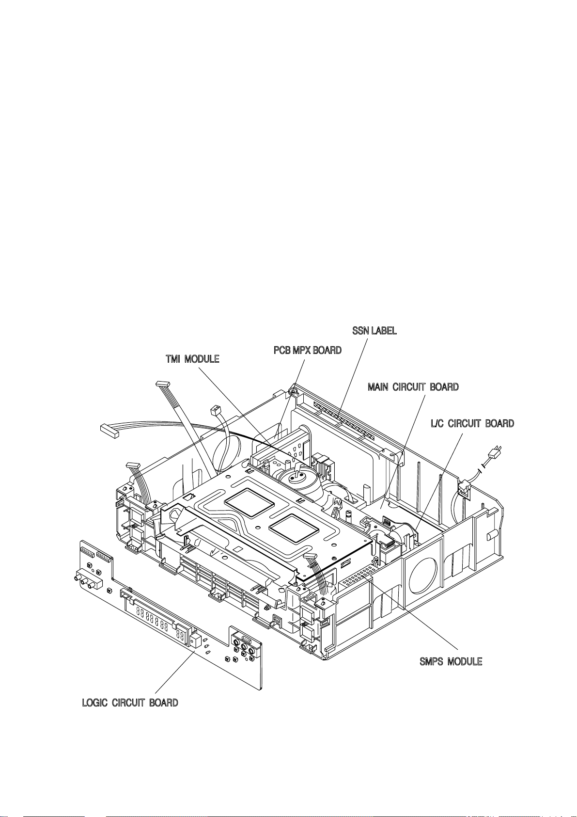
THE LOCATION OF THE "SSN LABEL"
The Location of the "SSN Label"
Page 5
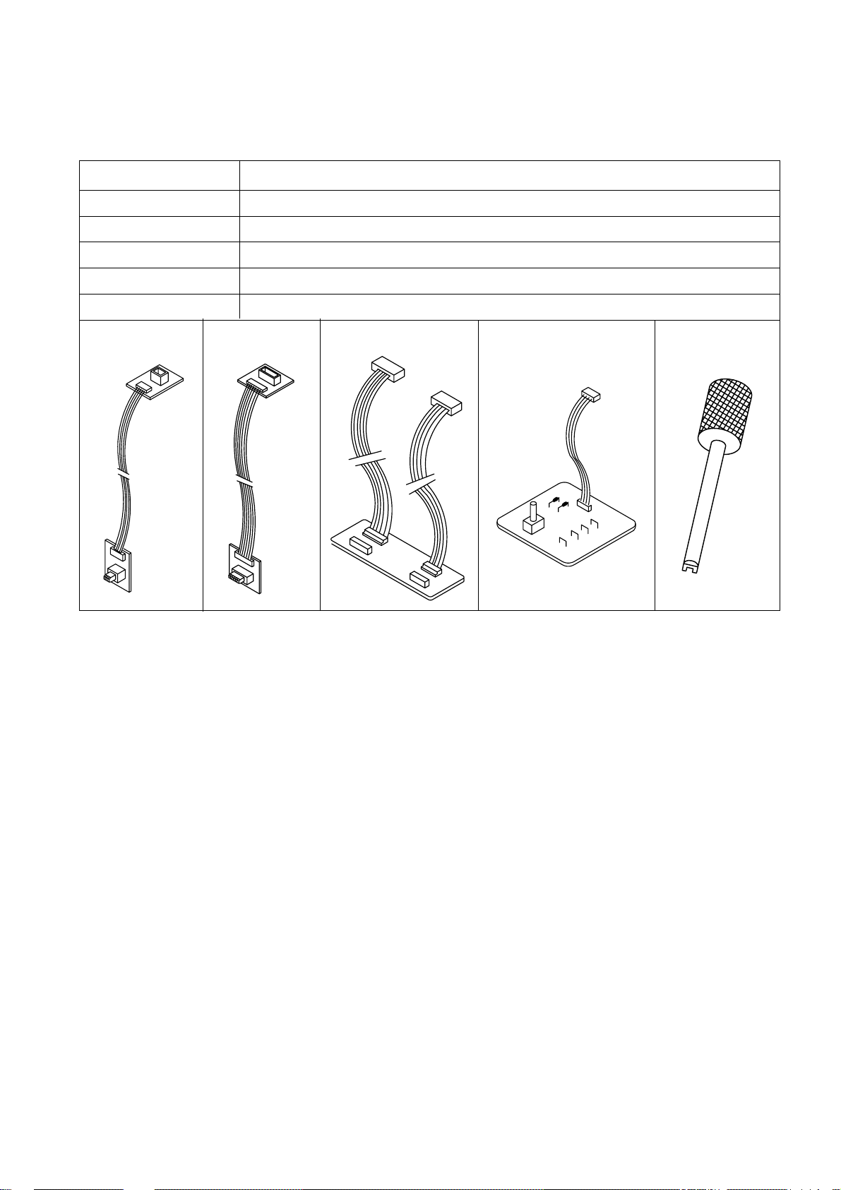
THE SERVICE FIXTURE
Cable 1 Cable 2 Cable 3 Path Adj Fixture Special Driver
5
FIXTURE ITEM DESCRIPTION
Extension Cable 1 Use for K mecha Drum Motor Connecting Cable
Extension Cable 2 Use for K mecha Capstan Motor connecting Cable
Extension Cable 3 Use for K mecha A/C head and L/C Motor Connecting Cable
Path Adj Fixture Use for X-position adjust/Tape path alignment
Special Driver Use for X-position adjust/Tape path alignment
Page 6
6
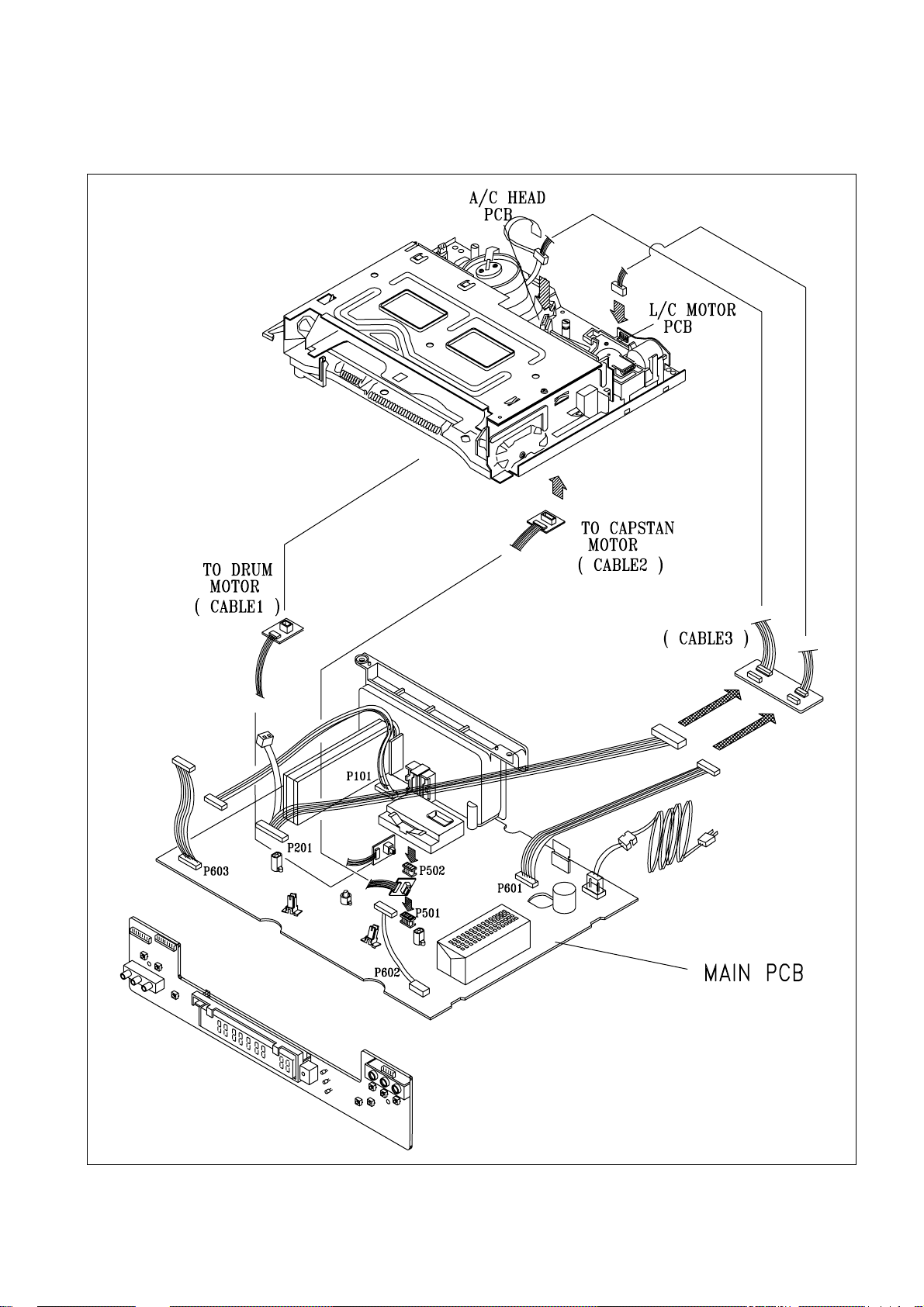
EXTENSION CABLE CONNECTION
Page 7
7
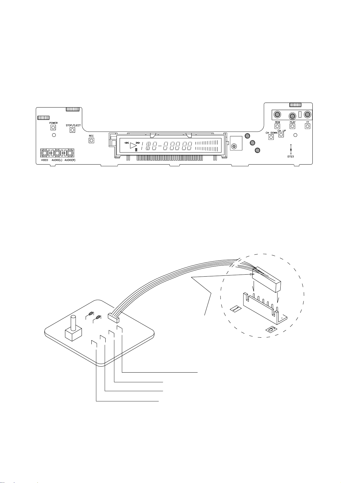
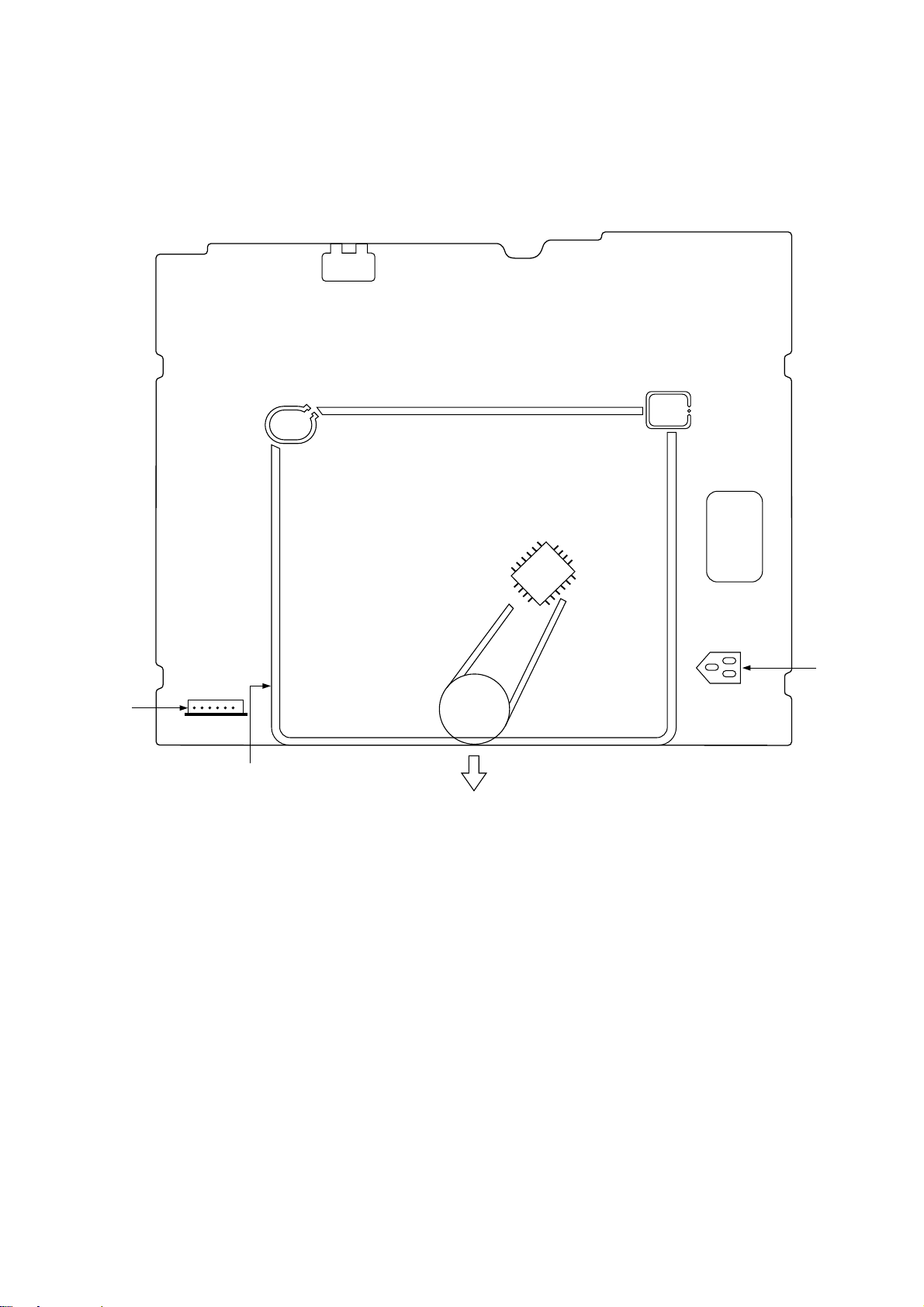
NOTE: PLACING THE UNIT IN THE SERVICE MODE
Service option
For this chassis, the sensors (start/end/reel) are located on the MAIN circuit board, not in the DECK assembly. There is an important
service option that has to be followed to repair the MAIN circuit board with the DECK assembly connected. To imitate the function of
the sensors, insert the SVC Mode Diode wire (D723) on the MAIN circuit board as shown below.
LOGIC PCB (FRONT SIDE)
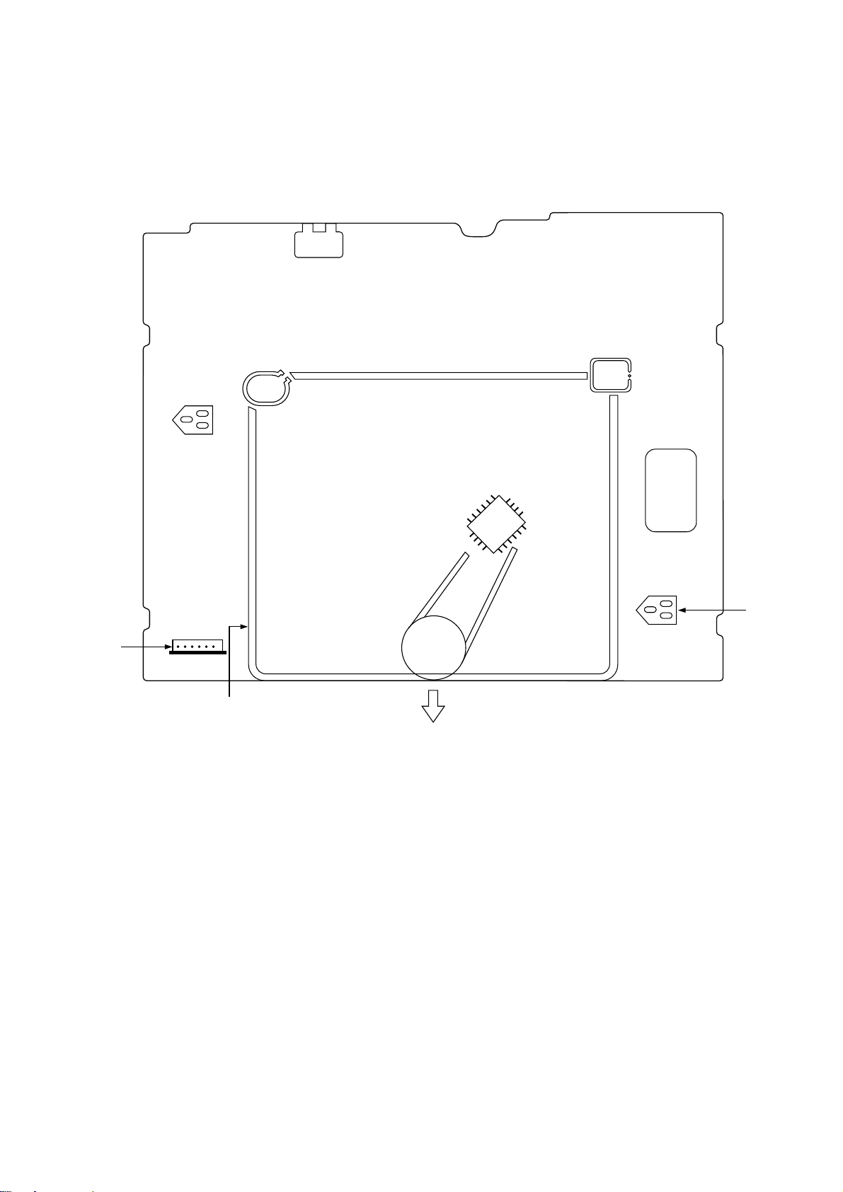
PATH FIXTURE CONNECTION/TEST POINT IDENTIFICATION
Refer to the adjustment of the tape transporting system.
Connect to PT01,
!pin-^pin of the
MAIN CIRCUIT BOARD.
CTL pulse test point
GND
S/W pulse test point
ENVE pulse test point
!
^
Page 8
8
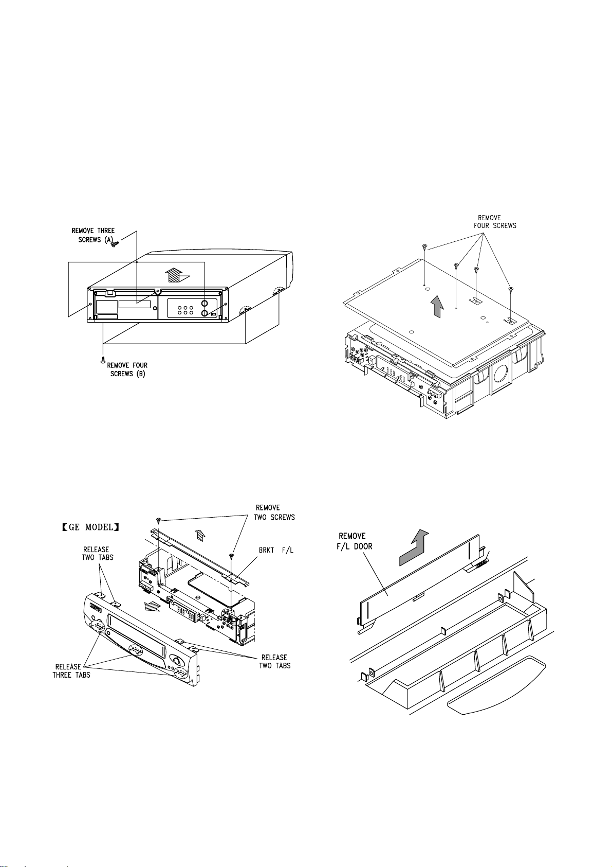
Top Cover Removal(Fig. 1)
1. Remove three screws(A) holding the top cover.
2. Remove four screws(B) holding the top/botton cover.
3. Carefully lift the back of the top cover and slide it to the rear
to remove it.
Front Panel Removal(Fig. 2)
1. Continued from (Fig. 1).
2. Remove two screws securing front panel & F/L bracket.
3. Remove the F/L brackat.
4. Release three bottom tabs holding the front panel.
5. Remove the front panel.
Bottom Cover Removal(Fig. 3)
1. Remove top cover and front panel.
2. Remove four screws.
3. Lift out the bottom cover in the direction of the arrow.
F/L Door Removal(Fig. 4)
1. Open the F/L door 90 degrees.
2. Remove the F/L door in the direction of the arrow.
Fig. 1 - Top Cover Removal
Fig. 3 - Bottom Cover Removal
Fig. 2 - Front Panel Removal
Fig. 4 - F/L Door Removal
INSTRUMENT DISASSEMBLY
Perform all disassembly procedures in the order presented. When reassembling, use the renerse procedure. Make sure that all
leads/wiring are routed correctly when reassembling.
Page 9
9
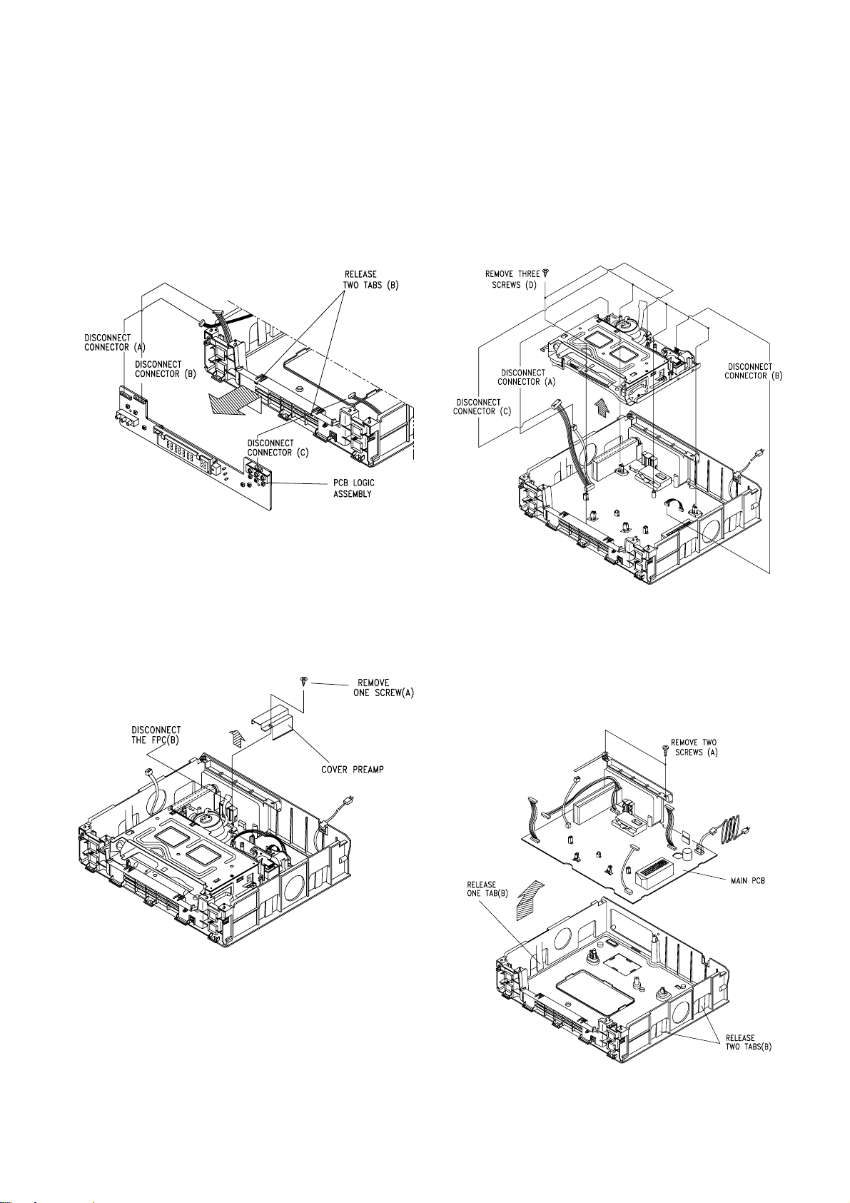
PCB Preamp Assembly Removal(Fig. 5)
1. Remove top cover and front panel.
2. Disconnect connectors (A,B,C).
3. Remove two(2) tabs (B) holding the PCB logic assembly.
4. Tilt the PBC Logic Assembly forward and remove it in the
direction of the arrow.
COVER Preamp Removal(Fig. 6)
1. Remove top cover, bottom cover and front panel.
2. Remove one screw (A).
3. Remove the cover preamp in the direction of the arw.
4. Disconnect the FPC (B).
Deck Assembly Removal(Fig. 7)
1. Remove top cover, bottom cover, front panel.
2. Disconnect three connectors (A) (B) (C).
3. Remove three screws (D).
4. Pull out the Deck Assembly in the direction of the arrow.
Main PCB Assembly Removal(Fig. 8)
1. Remove top cover, bottom cover, front panel.
2.Remove three screws (A).
3. Release three tabs (B) and lift out the Main PCB in the
direction of the arrow.
Fig. 5 - PCB Preamp Assembly Removal
Fig. 6 - COVER Preamp Removal
Fig. 7 - Deck Assembly Removal
Fig. 8 - Main PCB Removal
INSTRUMENT DISASSEMBLY (Continued)
Page 10
10
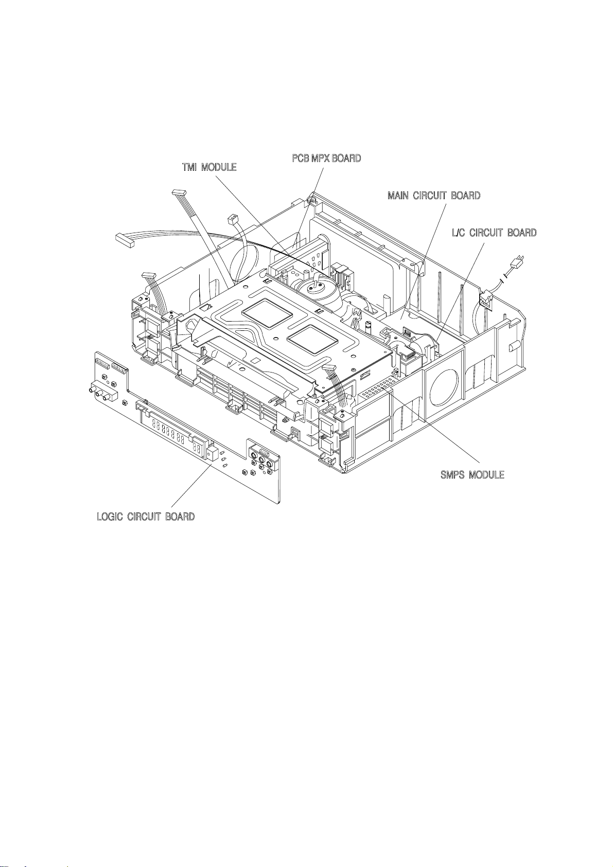
ELECTRICAL ADJUSTMENT
Fig. 1 - Circuit Board Location
Page 11
11
ELECTRICAL ADJUSTMENTS (Hi-Fi MODEL)
FRONT
A/V JACK
DECK ASSEMBLY
PT01
POWER
SUPPLY
#3
SW30Hz
R199
STEREO
SEPARATION
PG
SHIFTER
R599
Fig. 2 - Main board test point/control location guide (Component)
ƒRConnect the Fixture (6pin) to ! pin–^pin of PT01
ƒR
Page 12
12
ELECTRICAL ADJUSTMENTS (4HEAD MODEL)
FRONT
A/V JACK
DECK ASSEMBLY
PT01
POWER
SUPPLY
#3
SW30Hz
PG
SHIFTER
R599
Fig. 3 - Main board test point/control location guide (Component)
ƒRConnect the Fixture (6pin) to ! pin–^pin of PT01
ƒR
Page 13
13
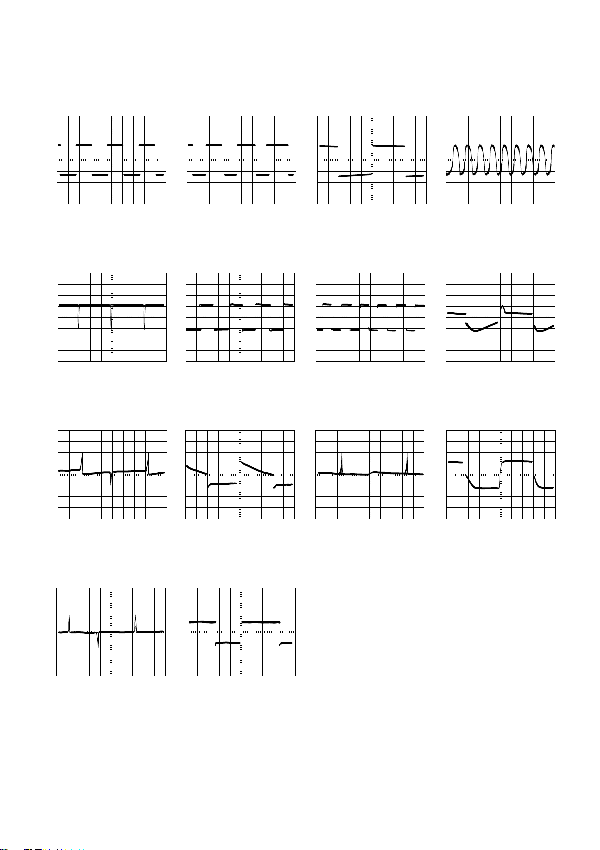
SERV O WAVEFORMS
!
(IC601-3) 5.6Vp-p
2V/5µsec/cm
REC/PLAY
@
(IC601-4) 5.6Vp-p
2V/5µsec/cm
REC/PLAY
#
(IC601-18) 5.6Vp-p
2V/5msec/cm
REC/PLAY
$
(IC601-34) 5.6Vp-p
2V/50nsec/cm
REC/PLAY
%
(IC601-66) 4.8Vp-p
2V/10msec/cm
REC/PLAY
^
(IC601-67) 4.8Vp-p
2V/0.5msec/cm
REC/PLAY
&
(IC601-68) 4.8Vp-p
2V/0.5msec/cm
REC/PLAY
*
(IC601-71) 5.2Vp-p
2V/5msec/cm
REC
*
(IC601-71) 3Vp-p
1V/5msec/cm
PLAY
(
(IC601-72) 4.8Vp-p
2V/5msec/cm
REC
(
(IC601-72) 3Vp-p
1V/5msec/cm
PLAY
)
(IC601-73) 5Vp-p
2V/5msec/cm
REC
)
(IC601-73) 3Vp-p
1V/5msec/cm
PLAY
1
(IC601-77) 4Vp-p
2V/5msec/cm
REC
Page 14

14
LUMI/CHROMA WAVEFORMS
!
(IC301-14) 440mVp-p
200mV/10µsec/cm
REC
@
(IC301-15) 800mVp-p
200mV/10µsec/cm
PLAY
#
(IC301-17) 1.16Vp-p
500mV/10µs/cm
PLAY
$
(IC301-18) 340mVp-p
100mV/10µsec/cm
REC
%
(IC301-20) 1Vp-p
500mV/5ms/cm
PLAY
^
(IC301-26) 510mVp-p
200mV/10µsec/cm
REC
^
(IC301-26) 500mVp-p
200mV/10µsec/cm
PB
&
(IC301-28) 1Vp-p
500mV/10µsec/cm
REC
*
(IC301-37) 4.2Vp-p
2V/20µsec/cm
REC/PLAY
(
(IC301-38) 2.15Vp-p
500mV/10µsec/cm
REC
(
(IC301-38) 2.05Vp-p
500mV/10µsec/cm
PLAY
)
(IC301-40) 350mVp-p
100mV/10µsec/cm
REC
)
(IC301-40) 310mVp-p
100mV/10µsec/cm
PLAY
1
(IC301-42) 390mVp-p
100mV/10µsec/cm
REC
1
(IC301-42) 360mVp-p
100mV/10µsec/cm
PLAY
2
(IC301-45) 450Vp-p
200mV/10µsec/cm
PB
Page 15

15
LUMI/CHROMA WAVEFORMS
3
(IC301-14,50) 320mVp-p
200mV/10µsec/cm
REC
3
(IC301-48, 50) 240mVp-p
100mV/10µsec/cm
PB
4
(IC301-52) 320mVp-p
100mV/10µs/cm
REC
4
(IC301-52) 240mVp-p
100mV/10µsec/cm
PLAY
5
(IC301-55) 480Vp-p
200mV/0.5ms/cm
REC/PLAY
6
(IC301-56) 500mVp-p
200mV/0.5µsec/cm
REC
6
(IC301-56) 500mVp-p
200mV/0.5µsec/cm
PB
7
(IC301-58) 480mVp-p
200mV/0.5µsec/cm
REC
7
(IC301-58) 480mVp-p
200mV/0.5µsec/cm
PB
8
(IC301-60) 480Vp-p
200mV/0.5µsec/cm
REC/PB
Page 16

16
AUDIO WAVEFORMS
9
(IC301-73) 90mVp-p
20mV/0.2msec/cm
REC
0
(IC301-77) 1.5Vp-p
0.5V/0.2msec/cm
REC
“
(IC301-79) 0.4Vp-p
50mV/0.2msec/cm
REC
‘
(IC301-1) 2Vp-p
0.5V/0.2msec/cm
REC
+
(IC301-10) 85mVp-p
20mV/0.5msec/cm
PLAY
=
(T201-5) 60Vp-p
30V/20µsec/cm
REC
Q
(T201-6) 75Vp-p
40V/20µsec/cm
REC
Page 17
17
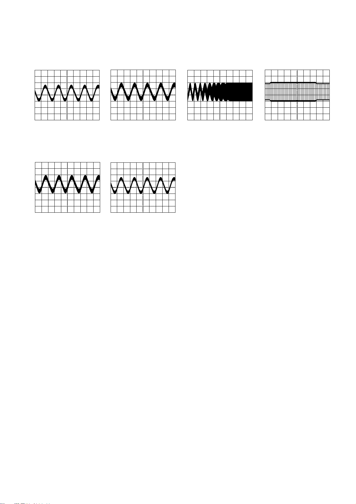
Hi-Fi AUDIO WAVEFORMS
q
(IC901-45) 360mVp-p
100mV/0.5msec
EE/REC/PLAY
W
(IC901-7) 900mVp-p
200mV/0.5msec
EE/REC
w
(IC901-22) 1100mVp-p
500mV/1msec
REC
E
(IC901-25) 400mVp-p
200mV/2msec
PLAY
e
(IC901-33) 900mVp-p
200mV/0.5msec
EE/REC
R
(IC901-47) 360mVp-p
100mV/0.5msec
EE/REC/PLAY
Page 18

18
SERV O/SYSCON/TIMER µ-COM VOLT AGE CHARTS
MODE µ-COM
PIN No.
STOP REC PLAY
REW/ REV/FWD REC PLAY
F.FWD SEARCH PAUSE PAUSE
1 0 2.7 3.2 2.6 3.2 5.3 5.3
20000000
3 0 2.7 2.7 2.7 2.7 0 5.3
4 2.4 2.4 0 2.3 2.4 2.3 2.4
5 5 0-5 0-5 0-5 0-5 0 0
6 5 0-5 0-5 0-5 0-5 0 0
70000000
8 5.3 5.3 0 5.3 0 5.3 0
90000000
10 2.6 2.6 0 2.6 2.6 2.6 2.6
11 5.2 5.2 5.2 0 5.2 5.2 5.2
12 2.7 2.7 2.8 2.8 2.8 0 0
13 5.3 0 0 5.3 0 0 0
14 0 5.3 0 5.3 5.3 5.3 5.3
15 2.6 2.6 0 2.6 3 2.6 5.3
160000202.6
17 0 0 0 0 2.3 0 2.5
18 2.6 2.6 2.6 2.6 2.6 2.6 2.6
190000000
20 5.3 2.6 0 2.6 2.6 2.6 2.6
MODE µ-COM
PIN No.
STOP REC PLAY
REW/ REV/FWD REC PLAY
F.FWD SEARCH PAUSE PAUSE
210000000
22 0 5.3 0 0 0 0 0
23 5.3 5.3 5.3 5.3 5.3 5.3 5.3
240000000
250000000
26 5.3 5.3 5.3 5.3 5.3 5.3 5.3
27 5.3 5.3 5.3 5.3 0 5.3 5.3
28 4.9 4.9 4.9 4.9 4.9 4.9 4.9
29 4.9 4.9 4.9 4.9 4.9 4.9 4.9
300000000
31 5.2 0 0 0 0 0 0
320000000
33 5.2 5.2 5.2 5.2 5.2 5.2 5.2
34 5.3 5.3 5.3 5.3 5.3 5.3 5.3
350000000
360000000
37 5.3 5.3 5.3 5.3 5.3 5.3 5.3
38 2.39 2.38 2.39 2.4 2.4 2.39 2.39
39 2.42 2.4 2.41 2.52 2.52 2.52 2.51
400000000
MODE POWER
PIN No.
STOP REC PLAY
REW/ REV/FWD REC PLAY
F.FWD SEARCH PAUSE PAUSE
CN11 CAUTION: TEST POINT (Pin (1) (2) ¡Œ(4) (5)
1 297 297 297 297 297 297 297
2 297 297 297 297 297 297 297
3 N.C N.C N.C N.C N.C N.C N.C
4 0.0 0.0 0.0 0.0 0.0 0.0 0.0
5 0.0 0.0 0.0 0.0 0.0 0.0 0.0
CN21
1 38.7 38.9 38.4 38.4 38.6 38.6 39.6
2 12.5 12.3 12.5 12.1 12.3 12.5 13.1
3 6.1 6.1 6.1 6.1 6.1 6.1 6.1
40000000
50000000
6 -28.0 -28.0 -28.0 -28.1 -27.7 -28.0 -28.1
7 -16.1 -16.0 -16.2 -15.7 -16.0 -16.0 -16.9
8 -21.1 -21.1 -21.2 -20.8 -21 -21 -22.0
MODE POWER
PIN No.
STOP REC PLAY
REW/ REV/FWD REC PLAY
F.FWD SEARCH PAUSE PAUSE
Q810
E 9.2 9.2 9.3 9.2 9.3 9.2 9.3
C 12.5 12.3 12.2 12.0 12.3 12.5 13.0
B 9.9 9.8 9.9 9.8 9.9 9.8 9.9
Q811
E 5.1 5.0 5.0 5.0 5.0 5.0 5
C 6.0 6.0 6.0 6.0 6.0 6.0 6.0
B 5.7 5.7 5.7 5.7 5.7 5.7 5.7
Q812
E0000000
C 9.8 9.8 9.8 9.8 9.8 9.8 9.9
B0000000
POWER VOLTAGE CHARTS
Page 19

19
SERV O/SYSCON/TIMER µ-COM VOLT AGE CHARTS
MODE µ-COM
PIN No.
STOP REC PLAY
REW/ REV/FWD REC PLAY
F.FWD SEARCH PAUSE PAUSE
410000000
42 1.24 1.25 1.25 1.24 1.24 1.25 12.5
43 1.2 1.2 1.2 1.2 1.2 1.2 1.2
44 0 0 5.3 0 5.3 0 5.3
45 0 0 0 0 5.3 0 5.3
46 0 0 0 0 5.3 0 5.3
47 4.5 4 4 4.2 4 4.4 4.4
48 4.7 4.3 4.3 4.4 4.3 4.5 4.5
49 0 0 4.1 0 0 0 0
50 5.2 5.2 5.2 5.2 5.2 5.2 5.2
51 5.2 5.2 5.2 0 5.2 5.2 5.2
52 0 5.2 5.2 5.2 0 0 0
53 0 0 0 0 5.2 0 0
540000000
550000000
560000000
570000000
580000000
59 5.3 5.3 5.3 5.3 5.3 5.3 5.3
60 0 0 0 0 5.3 0 0
61 0 0 5.3 0 5.3 0 0
62 0 0 0 5.3 0 0 0
630000000
64 5.3 5.3 0 5.3 0 5.3 0
65 5.2 5.2 5.2 5.2 5.2 5.2 5.2
66 0.25 4.5 4.4 4.4 4.4 4.4 4.4
67 4.6 2.4 2.4 2.4 2.4 2.4 2.4
68 5.1 2.6 2.6 2.6 2.5 5.1 5.1
69 2.6 2.6 2.6 2.6 2.6 2.6 2.6
70 2.6 2.6 2.6 2.6 2.6 2.6 2.6
MODE µ-COM
PIN No.
STOP REC PLAY
REW/ REV/FWD REC PLAY
F.FWD SEARCH PAUSE PAUSE
71 2.8 1.7 2.6 2.8 2 2.8 2.8
72 2.4 3.4 0 2.4 2.9 2.4 2.4
73 0 2.6 2.6 2.6 2.6 2.6 0
74 2.6 2.6 2.6 2.6 2.6 2.6 2.6
75 2.6 2.6 2.6 2.6 2.6 2.6 0
76 2.6 0 2.6 2.6 2.6 2.6 2.6
77 2.6 0 2.6 2.6 2.6 2.6 2.6
780000000
790000000
800000000
81 5.3 5.3 0 5.3 5.3 5.3 5.3
82 5.2 0 5.2 5.2 5.2 5.2 5.2
83 4.7 4.6 4.7 4.7 4.7 4.7 4.7
840000000
850000000
865555555
87000000.10
88 2.8 2.8 2.8 2.8 2.8 2.8 2.8
89 1.7 1 3.8 1.3 3.3 0 3.3
90 0-3 0-3 0-3 0-3 0 0-3 0
91 0-3 0-3 0-3 0-3 0 0-3 0-3
92 1.8 1.8 0.2 1.8 0.2 1.9 0.2
93 0.6 0.6 0.6 0.6 0.6 0.6 0.6
940000000
95 0.6 0.6 0.6 0.6 0.6 0.6 0.6
96 5.2 5.2 5.2 5.2 5.2 5.2 5.2
97 0.5 0.5 0.5 0.5 0.5 0.5 0.5
980000000
99 5.3 5.3 5.3 5.3 5.3 5.3 5.3
100 0 0 0 0 0 0 0
Page 20
20
MODE CI DRIVE (IC602)
PIN No.
STOP REC PLAY
REW/ REV/FWD REC PLAY
F.FWD SEARCH PAUSE PAUSE
10000000
2 0.5 0.5 0.5 0.5 0.5 0.5 0.5
3 0.9 0.9 0.9 0.9 0.9 0.9 0.9
4 6.3 6.3 6.3 6.3 6.3 6.3 6.3
50000000
60000000
7 12.25 12.15 12.28 11.98 12.15 12.24 12.82
8 12.25 12.15 12.28 11.98 12.15 12.24 12.82
9 0.95 0.95 0.95 0.95 0.95 0.95 0.95
10 0.5 0.5 0.5 0.5 0.5 0.5 0.5
MODE IC RESET (IC604)
PIN No.
STOP REC PLAY
REW/ REV/FWD REC PLAY
F.FWD SEARCH PAUSE PAUSE
1 5.3 5.3 5.3 5.3 5.3 5.3 5.3
2 5.3 5.3 5.3 5.3 5.3 5.3 5.3
30000000
VIDEO/AUDIO IC VOLTAGE CHARTS
MODE IC A/V
PIN No.
STOP REC PLAY
REW/ REV/FWD REC PLAY
F.FWD SEARCH PAUSE PAUSE
1 2.3 2.3 2.3 2.3 2.3 2.3 2.3
2 0.0 0.0 0.0 0.0 0.0 0.0 0.0
3 2.3 2.3 2.3 2.3 2.3 2.3 2.3
4 0.0 0.0 0.0 0.0 0.0 0.0 0.0
5 5.5 2.5 5.5 0.0 5.5 4.6 5.5
6 0.0 0.5 0.0 0.0 0.0 0.0 0.0
7 2.3 2.3 2.3 2.3 2.3 2.3 2.3
8 2.3 2.3 2.3 2.3 2.3 2.3 2.3
9 2.3 2.3 2.3 2.3 2.3 0 2.3
10 2.3 2.3 2.3 2.3 2.3 0 2.3
11 2.3 3.2 2.3 2.3 2.3 2.3 2.3
12 0.0 2.3 2.3 2.3 2.3 2.3 2.3
13 1.7 1.7 2.4 1.7 2.0 1.7 2.0
14 2.9 2.9 0.0 2.9 0.0 2.9 0.0
15 0.0 0.0 3.2 0.0 2.3 0.2 2.3
16 2.6 2.6 2.6 2.6 2.6 2.6 2.6
17 2.6 2.6 1.5 2.6 1.5 2.6 1.5
18 2.2 2.2 2.5 2.2 2.5 2.2 2.5
19 0.0 3.9 0.0 0.0 0.0 0.0 0.0
20 3.1 3.1 3.1 3.1 0.0 0.0 0.0
21 0.0 0.0 0.0 0.0 4.2 0.0 4.2
22 1.6 1.6 2.6 1.6 2.6 1.6 2.2
23 0.0 0.0 1.8 0.0 1.8 0.0 1.8
24 2.3 2.3 1.8 2.3 1.8 2.3 1.8
25 2.1 2.1 1.9 2.1 2.1 2.1 1.9
26 3.0 3.0 1.9 3.0 1.9 3.0 3.0
27 0.0 0.0 0.0 0.0 0.0 0.0 0.0
MODE IC A/V
PIN No.
STOP REC PLAY
REW/ REV/FWD REC PLAY
F.FWD SEARCH PAUSE PAUSE
28 2.0 2.0 0.0 2.0 0.0 2.0 0.0
29 2.1 2.1 2.1 2.1 2.1 2.1 2.1
30 1.8 1.8 0.0 1.8 0.0 1.8 0.0
31 4.1 4.1 4.1 4.1 4.1 4.1 4.1
32 1.7 1.7 0.0 1.7 0.0 0.0 0.0
33 0.0 0.0 0.0 0.0 0.0 0.0 0.0
34 2.1 2.1 2.1 2.1 2.1 2.1 2.1
35 3.0 3.0 3.0 3.0 3.0 3.0 3.0
36 5.0 5.0 5.0 5.0 5.0 5.0 5.0
37 0.3 0.3 0.3 0.3 0.0 0.3 0.3
38 1.4 1.4 1.4 1.4 1.4 1.4 1.4
39 3.1 3.1 3.1 3.1 3.1 3.1 3.1
40 3.0 3.0 3.0 3.0 3.0 3.0 3.0
41 4.2 4.2 4.2 4.2 4.2 4.2 4.2
42 2.0 2.0 2.0 2.0 2.0 2.0 2.0
43 0.4 0.4 0.4 0.4 0.4 0.4 0.4
44 1.7 1.7 1.7 1.7 1.7 1.7 1.7
45 1.9 1.9 1.9 1.9 0.0 1.9 0.0
46 0.2 0.2 2.7 0.2 2.7 0.2 0.0
47 5.0 5.0 5.0 5.0 5.0 5.0 5.0
48 2.8 2.8 2.8 2.8 2.8 2.8 2.8
49 4.1 4.1 4.1 4.1 4.1 4.1 4.1
50 2.9 2.9 2.9 2.9 2.9 2.9 2.9
51 4.1 4.1 4.1 4.1 4.1 4.1 4.1
52 3.2 3.2 3.2 3.2 3.2 3.2 3.2
53 0.0 0.0 0.0 0.0 0.0 0.0 0.0
54 2.2 2.2 2.2 2.2 2.2 2.2 2.2
Page 21

21
VIDEO/AUDIO IC VOLTAGE CHARTS
MODE IC A/V
PIN No.
STOP REC PLAY
REW/ REV/FWD REC PLAY
F.FWD SEARCH PAUSE PAUSE
55 4.0 4.0 4.0 4.0 4.0 4.0 4.0
56 2.5 2.5 2.5 2.5 2.5 2.5 2.5
57 0.0 0.0 0.0 0.0 0.0 0.0 0.0
58 2.4 2.4 2.4 2.4 2.4 2.4 2.4
59 0.0 0.0 0.0 0.0 0.0 0.0 0.0
60 4.0 4.0 4.0 4.0 4.0 4.0 4.0
61 2.0 2.0 2.0 2.0 2.0 2.0 2.0
62 0.0 0.0 0.0 0.0 0.0 0.0 0.0
63 0.1 0.1 0.1 0.1 0.1 0.1 0.1
64 0.1 0.1 0.1 0.1 0.1 0.1 0.1
65 0.3 0.3 0.3 0.3 0.3 0.3 0.3
66 0.0 0.0 0.0 0.0 0.0 0.0 0.7
67 0.0 0.0 0.0 0.0 0.0 0.0 0.0
MODE IC A/V
PIN No.
STOP REC PLAY
REW/ REV/FWD REC PLAY
F.FWD SEARCH PAUSE PAUSE
68 0.9 0.9 0.9 0.9 0.9 0.9 0.9
69 2.6 2.6 2.6 2.6 2.6 2.6 2.6
70 0.0 0.0 0.0 0.0 4.9 0.0 4.9
71 2.3 2.3 2.3 2.3 2.3 2.3 2.3
72 0.0 0.0 0.0 0.0 0.0 0.0 0.0
73 2.3 2.3 2.3 2.3 2.3 2.3 2.3
74 2.3 2.3 2.3 2.3 2.3 2.3 2.3
75 2.3 2.3 2.3 2.3 2.3 2.3 2.3
76 5.1 5.1 5.1 5.1 5.1 5.1 5.1
77 2.3 2.3 2.3 2.3 2.3 2.3 2.3
78 0.0 0.0 0.0 0.0 0.0 0.0 0.0
79 2.3 2.3 2.3 2.3 2.3 2.3 2.3
80 0.0 0.0 0.0 0.0 0.0 0.0 0.0
CCD & HEADAMP IC VOLTAGE CHARTS
MODE IC CCD
PIN No.
STOP REC PLAY
REW/ REV/FWD REC PLAY
F.FWD SEARCH PAUSE PAUSE
1 2.3 2.3 2.3 2.3 2.3 2.3 2.3
2 5.0 5.0 5.0 5.0 5.0 5.0 5.0
3 2.3 2.3 2.3 2.3 2.3 2.3 2.3
4 0.0 0.0 0.0 0.0 0.0 0.0 0.0
5 2.0 2.0 2.0 2.0 2.0 2.0 2.0
6 4.2 4.2 4.2 4.2 4.2 4.2 4.2
7 1.5 1.5 1.5 1.5 1.5 1.5 1.5
MODE IC CCD
PIN No.
STOP REC PLAY
REW/ REV/FWD REC PLAY
F.FWD SEARCH PAUSE PAUSE
8 9.5 9.5 9.5 9.5 9.5 9.5 9.5
9 2.5 2.5 2.5 2.5 2.5 2.5 2.5
10 0.9 0.9 0.9 0.9 0.9 0.9 0.9
11 0.0 0.0 0.0 0.0 0.0 0.0 0.0
12 0.4 0.4 0.4 0.4 0.4 0.4 0.4
13 1.9 1.9 1.9 1.9 1.9 1.9 1.9
14 0.0 0.0 0.0 0.0 0.0 0.0 0.0
MODE IC HEADAMP (LA70011:4'CH)
PIN No.
STOP REC PLAY
REW/ REV/FWD REC PLAY
F.FWD SEARCH PAUSE PAUSE
1 2.0 2.0 2.0 2.0 3.8 2.0 3.8
2 0.0 0.0 0.0 0.0 0.5 0.0 0.5
3 0.0 0.0 0.0 0.0 0.0 0.0 0.0
4 0.0 0.0 0.0 0.0 0.0 0.0 0.0
5 0.1 0.1 0.1 0.1 0.1 0.1 0.1
6 0.9 0.5 4.2 0.9 3.0 2.5 3.5
7 1.7 0.0 1.7 1.7 1.7 1.7 1.7
8 0.0 0.0 0.0 0.0 0.0 0.0 0.0
9 0.0 3.5 0.0 0.0 0.0 0.0 0.0
10 0.0 3.5 0.0 0.0 0.0 0.0 0.0
11 0.0 3.9 0.0 0.0 0.0 0.0 0.0
12 2.5 2.5 2.5 2.5 2.5 2.5 2.5
MODE IC HEADAMP (LA70011:4'CH)
PIN No.
STOP REC PLAY
REW/ REV/FWD REC PLAY
F.FWD SEARCH PAUSE PAUSE
13 5.0 5.0 5.0 5.0 5.0 5.0 5.0
14 5.0 4.4 5.0 5.0 5.0 5.0 5.0
15 0.0 1.5 0.0 0.0 0.0 0.0 0.0
16 2.0 4.0 2.0 2.0 2.0 2.0 2.0
17 2.0 4.0 2.0 2.0 2.0 2.0 2.0
18 0.0 2.5 0.0 0.0 0.0 0.0 0.0
19 2.0 4.0 2.0 2.0 2.0 2.0 2.0
20 0.0 0.0 0.0 0.0 0.0 0.0 0.0
21 0.6 0.9 0.6 0.6 2.0 0.6 2.0
22 0.6 0.6 0.6 0.6 0.6 0.6 0.6
23 0.0 2.5 0.0 0.0 0.0 0.0 0.0
24 0.6 0.9 0.6 0.6 2.0 0.6 2.0
Page 22

22
HEADAMP IC VOLTAGE CHARTS
MODE IC HEADAMP (LA70020:6'CH)
PIN No.
STOP REC PLAY
REW/ REV/FWD REC PLAY
F.FWD SEARCH PAUSE PAUSE
1 5.06 5.02 5.05 5.05 5.04 5.07 5.05
2 2.149 4.0 2.14 2.15 2.14 2.15 2.14
3 0.0 2.4 0.0 0.0 0.0 0.0 0.0
4 2.15 3.94 2.14 2.15 2.14 2.15 2.14
5 2.15 4.0 2.14 2.15 2.14 2.15 2.14
6 0.0 0.0 0.0 0.0 0.0 0.0 0.0
7 2.0 2.0 2.0 2.0 3.8 2.0 3.8
8 0.0 0.0 0.0 0.0 0.5 0.0 0.5
9 0.0 0.0 0.0 0.0 0.0 0.0 0.0
10 0.0 0.0 0.0 0.0 0.0 0.0 0.0
11 0.1 0.1 0.1 0.1 0.1 0.1 0.1
12 0.9 0.5 4.2 0.9 3.0 2.5 3.5
13 1.7 0.0 1.7 1.7 1.7 1.7 1.7
14 0.0 0.0 0.0 0.0 0.0 0.0 0.0
15 0.0 3.5 0.0 0.0 0.0 0.0 0.0
16 0.0 3.5 0.0 0.0 0.0 0.0 0.0
17 0.0 3.9 0.0 0.0 0.0 0.0 0.0
18 2.5 2.5 2.5 2.5 2.5 2.5 2.5
MODE IC HEADAMP (LA70020:6'CH)
PIN No.
STOP REC PLAY
REW/ REV/FWD REC PLAY
F.FWD SEARCH PAUSE PAUSE
19 5.0 5.0 5.0 5.0 5.0 5.0 5.0
20 5.0 4.4 5.0 5.0 5.0 5.0 5.0
21 0.0 1.5 0.0 0.0 0.0 0.0 0.0
22 2.0 4.0 2.0 2.0 2.0 2.0 2.0
23 2.0 4.0 2.0 2.0 2.0 2.0 2.0
24 0.0 2.5 0.0 0.0 0.0 0.0 0.0
25 2.0 4.0 2.0 2.0 2.0 2.0 2.0
26 0.0 0.0 0.0 0.0 0.0 0.0 0.0
27 0.6 09 0.6 0.6 2.0 0.6 2.0
28 0.6 0.6 0.6 0.6 0.6 0.6 0.6
29 0.0 2.5 0.0 0.0 0.0 0.0 0.0
30 0.6 0.9 0.6 0.6 2.0 0.6 2.0
31 0.02 1.41 1.39 1.39 1.39 1.39 1.39
32 1.75 0.78 1.74 1.75 1.74 1.75 1.74
33 0.0 0.70 0.0 0.0 0.0 0.0 0.0
34 0.0 2.97 0.0 0.0 0.0 0.0 0.0
35 0.0 0.0 0.0 0.0 0.0 0.0 0.0
36 2.85 3.52 2.84 2.84 2.80 2.85 2.81
OSD VOLTAGE CHARTS
MODE IC OSD
PIN No.
STOP REC PLAY
REW/ REV/FWD REC PLAY
F.FWD SEARCH PAUSE PAUSE
10000000
2 4.7 4.7 4.7 4.7 4.7 4.7 4.7
3 5.1 5.1 5.1 5.1 5.1 5.1 5.1
4 0.0 0.0 0.0 0.0 0.0 0.0 0.0
5 2.0 2.0 2.0 2.0 2.0 2.0 2.0
6 2.0 2.0 2.0 2.0 2.0 2.0 2.0
7 0.0 0.0 0.0 0.0 0.0 0.0 0.0
8 0.1 0.1 0.1 0.1 0.1 0.1 0.1
9 0.1 0.1 0.1 0.1 0.1 0.1 0.1
10 0.1 0.1 0.1 0.1 0.1 0.1 0.1
11 0.0 0.0 0.0 0.0 0.0 0.0 0.0
12 0.0 0.0 0.0 0.0 0.0 0.0 0.0
13 5.3 5.3 5.3 5.3 5.3 5.3 5.3
14 0.0 0.0 0.0 0.0 0.0 0.0 0.0
15 5.1 5.1 5.1 5.1 5.1 5.1 5.1
MODE IC OSD
PIN No.
STOP REC PLAY
REW/ REV/FWD REC PLAY
F.FWD SEARCH PAUSE PAUSE
16 1.4 1.4 1.4 1.4 1.4 1.4 1.4
17 5.0 5.0 5.0 5.0 5.0 5.0 5.0
18 1.04 1.4 1.4 1.4 1.4 1.4 1.4
19 0.0 0.0 0.0 0.0 0.0 0.0 0.0
20 2.3 2.3 2.3 2.3 2.3 2.3 2.3
21 2.0 2.0 2.0 2.0 2.0 2.0 2.0
22 0.0 0.0 0.0 0.0 0.0 0.0 0.0
23 0.2 0.2 0.2 0.2 0.2 0.2 0.2
24 2.7 2.7 2.7 2.7 2.7 2.7 2.7
25 2.3 2.3 2.3 2.3 2.3 2.3 2.3
26 2.3 2.3 2.3 2.3 2.3 2.3 2.3
27 2.5 2.5 2.5 2.5 2.5 2.5 2.5
28 2.5 2.5 2.5 2.5 2.5 2.5 2.5
29 0.0 0.0 0.0 0.0 0.0 0.0 0.0
30 5.1 5.1 5.1 5.1 5.1 5.1 5.1
Page 23

23
AUDIO Hi-Fi VOLTAGE CHARTS (Hi-Fi ONLY)
MODE IC OSD
PIN No.
STOP REC PLAY
REW/ REV/FWD REC PLAY
F.FWD SEARCH PAUSE PAUSE
IC901
1 4.4 4.4 4.4 4.4 4.4 4.4 4.4
2 4.5 4.5 4.5 4.5 4.5 4.5 4.5
3 4.5 4.5 4.5 4.5 4.5 4.5 4.5
4 4.5 4.5 4.5 4.5 4.5 4.5 4.5
5 4.5 4.5 4.5 4.5 4.5 4.5 4.5
6 4.5 4.5 4.5 4.5 4.5 4.5 4.5
7 4.5 4.5 4.6 4.6 4.6 4.5 4.5
80000000
9 4.5 4.5 4.5 4.5 4.5 4.5 4.5
1000005.205.2
11 4.5 4.5 4.5 4.5 4.5 4.5 4.5
120000000
13 4.5 4.5 4.5 4.5 4.5 4.5 4.5
140000000
150000000
160000000
17 4.9 4.6 4.5 4.5 4.5 4.8 4.8
18 4.8 4.4 4.4 4.4 4.4 4.6 4.7
19 4.6 4.1 4.6 4.1 4.1 4.6 4.4
200000000
210000000
22 1.6 0.9 1.6 1.2 0.7 1.5 0.5
23 5.1 5.1 5.1 5.1 5.1 5.1 5.1
24 0 0.9 1.5 0 1.5 0 1.5
25 1.9 3.5 1.9 1.9 1.9 1.9 1.9
26 0 0 3.6 0 0 0 0.9
2700004.504.4
28 4.6 4.6 4.6 4.6 4.6 4.6 4.6
290000000
30 2.4 2.4 0.8 2.4 0.8 2.4 0.8
31 4.5 4.5 4.5 4.0 4.0 4.5 4.5
320000000
33 4.5 4.5 4.5 4.5 4.5 4.5 4.5
34 4.5 4.5 4.5 4.5 4.5 4.5 4.5
35 4.5 4.5 4.5 4.5 4.5 4.5 4.5
36 4.5 4.5 4.5 4.5 4.5 4.5 4.5
MODE IC OSD
PIN No.
STOP REC PLAY
REW/ REV/FWD REC PLAY
F.FWD SEARCH PAUSE PAUSE
Page 24

24
TMI PIN VOLTAGE (MONO/Hi-Fi)
MODE
PIN NO NAME EE. REC EE. REC REMARK
(TUNER) (LINE)
1 AUDIO IN 0 0
2 CH S/W 0.3 0.3 3CH:2.8V
3 5V 4.9 4.9
4 TV VCR 5.3 5.3 TV:0V
5 VIDEO IN 1.3 1.3
6 5V 5.0 5.0
7 32V 31.0 31.2
8 PLL CLK 0 0
9 PLL DATA 0 5.3
MODE
PIN NO NAME EE. REC EE. REC REMARK
(TUNER) (LINE)
10 PLL STB 0 0
11 N.C 0 4.8
12 N.C 0 0
13 9V 8.8 0.7
14 AUDIO OUT 3.8 0
15 N.C 0 0
16 AFT 4.2 0.3
17 N.C 0 0
18 VIDEO OUT 5.7 5.7
MPX MODULE PIN VOLTAGE (Hi-Fi ONLY)
MODE
PIN NO NAME EE. REC EE. REC REMARK
(TUNER) (LINE)
1 Vcc 8.9 0.7
2 N.C 0 0
3 L-OUT 4.4 0
4 R-OUT 4.4 0
5 A•MUTE 0 0 A.MUTE:5.3V
6 GND 0 0
7 FORCE (SW1) 0 0 F.M:5V
8
MSO (SW2)
0 0 STEREO:0V
SAP:5V
MODE
PIN NO NAME EE. REC EE. REC REMARK
(TUNER) (LINE)
9
MSI (SW2)
4.5 4.6 STEREO:5V
SAP:0V
10 SAP IND 5.0 5.0 SAP:0V
11 ST IND 5.0 5.0 STEREO:0V
12 MPX IN 4.4 0
13 GND 0 0
Page 25

25
NO NAME PORT IN/OUT ASSIGNMENT ACTIVE
1 CTL TEST P80/CSTO/RTSO OUTPUT CONTROL PLUSE TEST PORT PULSE
2 N.C P77/PWM2 3 CAP PWM P76PWM1 OUTPUT CAPSTAL CONTROL PWM OUTPUT PULSE
4 DRUM PWM P75/PWM0 OUTPUT DRUM CONTROL PWM OUTPUT PULSE
5 SUPPLY R/P P74/INT1 INPUT SUPPLY REEL PULSE PULSE
6 TAKE-UP R/P P73/INT0 INPUT TAKE UP REEL PULSE PULSE
7 PAL-M/NTSC P72/TB3IN OUTPUT PAL-M/NTSC MODE SWITCHING HIGH
8 PIF ON(H) P71/TBIN OUTPUT IN TUNER MODE, HIGH OUTPUT H/L
9 PLL STB P70/TB0IN OUTPUT PLL STROBE LOW
10 SERVO REF P67/RTP15/P-Hsy INPUT REFERENCE Vcc
11 REMOCON IN P66/RTP14/GEN INPUT REMOCON DATA INPUT PORT PULSE
12 CAP I.LIM P65/RTP13 OUTPUT CAPSTAN I. CONTROL LOW
13 CAP F/R P64/RTP12 OUTPUT CAPSTAN MOTOR FWD/RVS L/H
14 STEREO/SAP P63/RTP11 OUTPUT STEREO/SAP SWITCHING PORT LOW
15 COLOR ROT P62/RPT10/EXOR OUTPUT COLOR ROTARY PULSE
16 HA.SW P61/RTP9/EXOR OUTPUT HEAD AMP SWITCHING PULSE
17 ENVE COMP P60/RTP/8EXOR INPUT ENVE COMPARE PULSE
18 V.SW P57/RTP7 OUTPUT VIDEO SWITSHING PULSE
19 QV.SYNC P56/RTP6 OUTPUT Q.Vsync OUTPUT PULSE
20 A.SW P55/RTP5 OUTPUT AUDIO SWITCHING PULSE
21 50/60Hz P54/RTP4 OUTPUT 50/60Hz SWITCHING HIGH
22 REC(H) P53/RTP3 OUTPUT IN REC MODE, HIGH OUTPUT HIGH
23 SP(H) P52/RTP2 OUTPUT
24 LP(H) P51/RTP1 OUTPUT IN LP MODE, HIGH OUTPUT HIGH
25 EP(H) P50/RTP0 OUTPUT
26 Vcc Vcc Vcc
27 TV/VCR P47 OUTPUT TV/VCR MODE SWITCHING LOW
28 STERE0(L) P46 INPUT IN STEREO MODE, LOW INPUT LOW
29 SAP(L) P45 OUTPUT IN SAP MODE, LOW INPUT LOW
30 50Hz SP(H) P44 OUTPUT 50Hz SP SEARCH(H) PULSE
31 REC SAFTY P43 INPUT REC SAFETY SW DATA IN PULSE
32
FORCED MONO(H)
P42 OUTPUT IN FORCED MONO, HIGH OUTPUT PULSE
33 DRUM SEL P41 INPUT SYSTEM DRUM SELECT L/H
34 N.C P40
35 GND NUMA GND
36 GND NUMB GND
37 RESET RESET INPUT RESET INPUT PORT LOW
38 OSC 1 IN Xin INPUT 16MHz OSC IN
39 OSC 1 OUT Xout OUTPUT 16MHz OSC OUT
40 CLK SEL CLKSEL INPUT GND
41 Vss Vss GND
42 OSC 2 IN P140/Xcin INPUT 32.768KHz OSC IN
43 OSC 2 OUT Xcout OUTPUT 32.768KHz OSC OUT
44 N.C. P32
45 TRICK(H) P31 OUTPUT IN TRICK PLAY MODE, HIGH OUTPUT HIGH
46 A.MUTE(H) P30 OUTPUT AUDIO MUTE HIGH OUTPUT L/H
47 II2 DATA P21 IN/OUT Hi-Fi, A/V,EEPROM IC DATA SERIAL SERIAL
48 II2 CLK P20 OUTPUT Hi-Fi, A/V, EEPROM IC CLOCK SERIAL SERIAL
49 Hi-Fi(H) P17 INPUT Hi-Fi HIGH INPUT LOW
50 CAM A P16 INPUT CAM DATA INPUT PULSE
PIN NAME & FUNCTION OF MICOM
Page 26

26
NO NAME PORT IN/OUT ASSIGNMENT ACTIVE
51 CAM B P15 INPUT CAM DATA INPUT LOW
52 CAM C P14 INPUT CAM DATA INPUT LOW
53 CAM D P13 INPUT CAM DATA INPUT LOW
54 LM ON P12 OUTPUT LOADING MOTOR ON PULSE
55 LM F/R P11 OUTPUT LOADING MOTOR FWD/RVS PULSE
56 EJECT OUT (H) P10 OUTPUT CASSETTE DOWN OUT HIGH
57 PAL LED P07 OUTPUT IN PAL-M MODE, HIGH OUTPUT HIGH
58 NTSC LED P06 OUTPUT IN NTSC MODE, HIGH OUTPUT HIGH
59 AUTO LED P05 OUTPUT IN AUTO MODE, HIGH OUTPUT HIGH
60 REW LED P04 OUTPUT IN REW/REV, HIGH OUTPUT HIGH
61 PLAY LED P03 OUTPUT IN PLAY MODE, HIGH OUTPUT HIGH
62 FF LED P02 OUTPUT IN FF/QUICK VIEW, HIGH OUTPUT HIGH
63 POWER ON (L) P01 OUTPUT IN POWER ON, LOW OUTPUT LOW
64 PB (L) P00 OUTPUT
65 AMP VCC AMP Vcc INPUT AMP Vcc
66 DRUM PG DRPGin INPUT DRUM PG INPUT PULSE
67 DRUM FG DRFGin INPUT DRUM FG INPUT PULSE
68 CAP FG CPFGin INPUT CAPSTAN FG INPUT PULSE
69 AMP REF OUT AMPVrefout OUTPUT AMP REFERENCE OUT
70 AMP REF IN Vrefin INPUT AMP REFERENCE IN
71 CTL CLAMP(+) CLAMPF OUTPUT REFERENCE TO CTL CIRCUIT
72 CTL CLAMP(-) CLAMPR OUTPUT REFERENCE TO CTL CIRCUIT
73 CTL AMP OUT CTLAMPout OUTPUT REFERENCE TO CTL CIRCUIT
74 CTL AMP C AMPC OUTPUT REFERENCE TO CTL CIRCUIT
75 CTL AMP IN CTLAMPin INPUT REFERENCE TO CTL CIRCUIT
76 CTL SW OUT CTL+Swout OUTPUT REFERENCE TO CTL CIRCUIT
77 CTL (+) CTL + OUTPUT REFERENCE TO CTL CIRCUIT
78 CTL (-) CTL - OUTPUT REFERENCE TO CTL CIRCUIT
79 CTL VSS CTL Vss GND
80 AMP VSS AMP Vss GND
81 VCC Vcc Vcc
82 VREF Vref REFERENCE Vcc
83 POWER FAIL (L) P101/C INPUT IN POWER FAIL, LOW INPUT LOW
84 KILLER IN (H) P100/INT2 INPUT
IN COLOR KILLER DETECT, HIGH INPUT
HIGH
85 TAPE START P97/AN7/Adtrg INPUT TAPE START SENSOR DATA INPUT A/D
86 PATH ADJ P96/AN6 INPUT USE FOR PATH ADJUST A/D
87 TAPE END P95/AN5 INPUT TAPE END SENSOR DATA INPUT A/D
88 PG DLY P94/AN4 INPUT PG DELAY ADJUST A/D
89 DC ENVE P93/AN3 INPUT VIDEO DC ENVE DETECT INPUT A/D
90 A. LEVEL L P92/AN2 INPUT L-CH AUDIO LECEL DETECT INPUT A/D
91 A. LEVEL R P91/AN1 INPUT R-CH AUDIO LEVEL DETECT INPUT A/D
92 AFT P90/AN0 INPUT AFT INPUT PORT A/D
93 C SYNC CSYNCin INPUT C.SYNC INPUT PORT PULSE
94 VFD DATA OUT P87/SOUT1 OUTPUT VFD DATA OUTPUT SERIAL
95 VFD DATA IN P86/SIN1 INPUT VFD DATA INPUT SERIAL
96 VFD CLK P85/SCLK1 OUTPUT VFD CLOCK SERIAL
97 VFD STB P84/SRDY1 OUTPUT VFD STROBE LOW
98 PLL/OSD DATA P83/TxD0 OUTPUT PLL/OSD DATA SERIAL
99 OSD STB P82/RxD0 OUTPUT OSD STROBE LOW
100 PLL/OSD CLK P81/CLK0 OUTPUT PLL/OSD CLOCK SERIAL
Page 27

27
GENERAL INFORMATIONS
Operation Modes
Play, still, slow (4 head only), frame advance (4 head only),
index search, commercial scan, speed forward (reverse) picture
search, record, record pause, fast forward and rewind, time
counter, zero search, automaitc and manual tracking operations
are possible.
4 HEAD
4 Video head system uses four video heads on the upper cylinder. Four video head (SP CH-1/CH-2, 48um/60um, LP/SLP
CH1/CH2: 28um/28um) are used during record and playback at
SP and LP/EP respectively.
Only Hi-Fi system uses two Hi-Fi audio heads (CH-1/CH-2:
28um/28um) on the upper cylinder.
Timer Recording
The programmable timer can be preset up to one year in
advance to record up to 8 preselected programs. (One Time
Program, Daily Program, Weekdays Program or Weekly
Program)
The timer turns your VCR on and off and changes channels
automatically.
One Touch Recording
One touch recording lets you record up to four hours without
using the timer program feature. The VCR turns off automatically at the end of the recording.
Picture Search
Searches for a specific tape location during playback by fast forwarding or rewinding the tape. Sound is turned off during picture search. Picture search works best for tapes recorded in SP or
SLP speed.
Time Counter
The time counter shows the actual time it takes to record a program or play back a segment of a prerecorded tape. It helps
locate the beginning or end of programs you taped.
The time counter resets to 0:00:00 when the tape is ejected from
the VCR.
Slow Motion
The tape is viewed in slow motion during play or play pause,
Sound is turned off during slow motion playback. Slow motion
works best in the SP or SLP speed.
FRAME ADVANCE
Lets you view one frame with each press of the button when the
tape is in stop-action pause. And advances the tape 60 seconds
during playback.
Zero Search
The zero search feature lets you quickly return to a counter reading of 0:00:00 anywhere on the tape. This is especially convenient when you want to watch a segment of a tape several times.
Automatic Power On
The VCR will automatically turn power on when you insert a
cassette without pressing the power button.
Automatic Playback
When you insert the cassette with the record safety tab removed,
the VCR will turn power on and playback automatically without
pressing power and play button.
If you use the cassette with record safety tab intact, the VCR
will turn power on automatically and be in stop mode but does
not playback.
Select OFF in MENU-PREFERENCES-Auto play if you do not
want a tape with its safety tab removed to start playback automatically.
Auto TV/VCR
Select ON if you watch the VCR on channel 3 or 4 of your TV.
The VCR will automatically switch the TV/VCR setting to VCR
every time the VCR is turned on, tape with the safety tab
removed is inserted, or you press PLAY.
Select OFF if you watch the VCR on the Video input of your
TV. The VCR indicator will not turn on automatically and the
signal from your antenna or cable to your TV will not be interrupted.
Automatic Rewind
The VCR automatically rewinds the tape when end of the tape is
reached. A tape automatically goes to rewind mode if it reaches
at the end in playback, forward search, normal record or slow
mode.
Rewind Shut-Off
If the VCR is in rewind mode and the power button is pushed,
the VCR continues to rewind the tape until the beginning is
reached.
Commercial Scan
This is useful for scanning commercials or short program segments. Press SEARCH once during playback to advance the
tape approximately 30 seconds. And press SEARCH twice during playback to advance the tape approximately 60 seconds.
TECHNICAL EXPLANATION INDEX.
Page 28

28
Index Search
Index search feature lets you automatically record on index mark
on the tape every time you stop and start recording. During playback, you can locate the program you want to play be searching
for the index marks. The VCR stops automatically at each point
of which new recording marked and previews a brief segment in
the play mode and continues to the playback until the next index
signal is reached.
Mode indication in the Multifunction Display
The VCR modes will be indicated in the multifunction display in
a sign or character, so the operator can see the mode easily. This
display will indicate: TAPE SPEED, NORMAL OPERATION
such as PLAY, REC, FF, REW etc.
Remote Control with Special Effects
This remote offers POWER, PLAY, STOP, RECORD,
REWIND, FAST FORWARD, PAUSE, TV/VCR SELECTION, NUMBER SELECTION (0 though 9), CHANNEL
DOWN/UP, INPUT, PREV CH, TAPE SPEED, FRAME
ADVANCE, SLOW, TRACKING UP, TRACKING DOWN,
MENU, SEARCH, CLEAR, DISPLAY. Two models which
adopt universal remote, i.e., VR518, VR611HF have 5 keys
more; VCR, TV, VOL +/– and mute.The VCR is compatible
with the GE/RCA remote.
On screen Display
White graphics will be displayed on a background. When VCR
is turned on, menu graphics are displayed on screen by pressing
the MENU button on the remote. The mode will be selected by
pressing the appropriate digit buttons on the remote.
Cable-Ready Frequency Synthesis Tuner
You can select unscrambled CABLE TV channels A-1 to A-5,
A-8 and A through w+84 just like broadcast channel without
using an external converter. The frequency-synthesis tuner can
select total 181 channels including 113 cable channels.
Page 29

29
CONNECTION DIAGRAM (VCR-505)
Page 30

30
POWER SUPPLY SCHEMATIC (VCR-505)
*C811(K525M)
0.1F/5.5V
Page 31
31
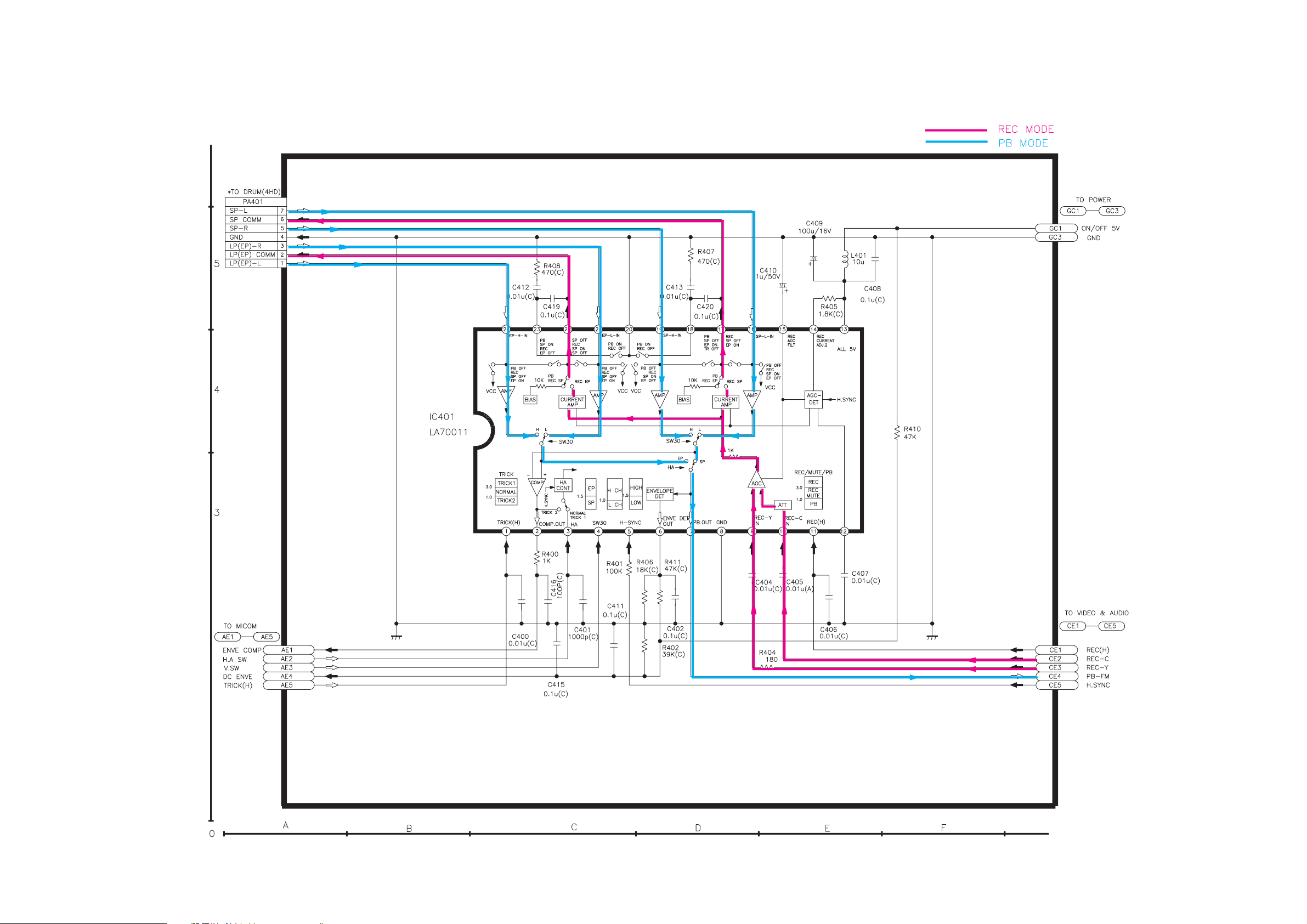
4HD(MONO) PREAMP CIRCUIT DIAGRAM (VCR-505)
Page 32

32
VIDEO & AUDIO SCHEMATIC DIAGRAM (VCR-505)
Page 33

33
PIF SCHEMATIC DIAGRAM (VCR-505)
Page 34
34
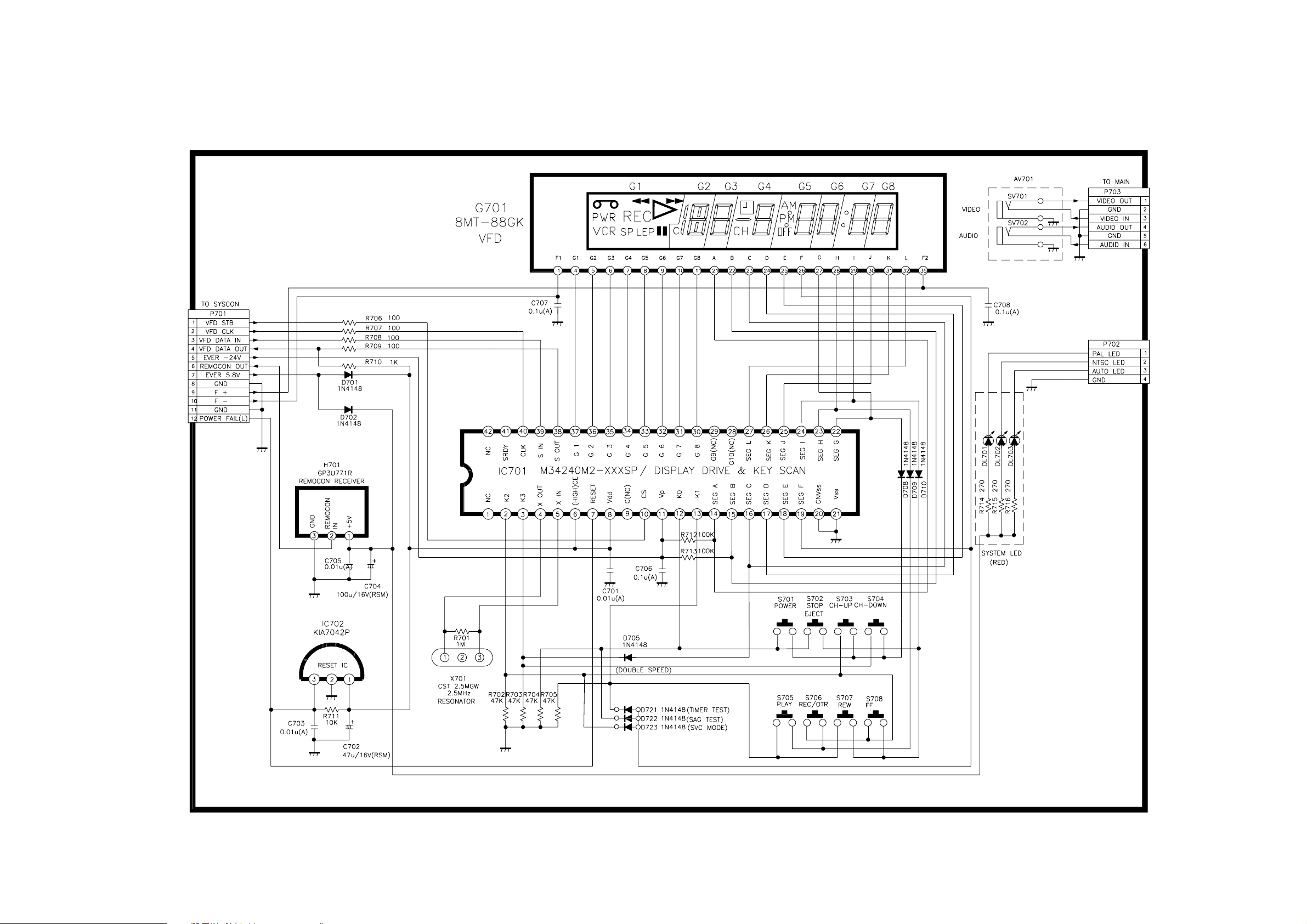
TIMER CIRCUIT (VCR-505)
Page 35

35
SERVO/SYSCON SCHEMATIC DIAGRAM (VCR-505)
L601
BI3857
Page 36

36
OSD SCHEMATIC DIAGRAM (VCR-505)
 Loading...