

Page 1

Service Manual
Model M-400
CCE da AMAZÔNIA
Cliente: Wal Mart – Argentina
Customer
CODE: 1.01.72360.50
_______________________________
Assinatura de Aprovação
Approved Signature
Page 2

M-400
1
INDEX
1. GENERAL..................................................................................................................................................................2
2. TECHNICAL SPECIFICATION........................................................................................................................4
2.1. PRODUCT:...............................................................................................................................................................4
2.2. SPECIFICATIONS:...............................................................................................................................................4
2.3. FUNCTIONS:...........................................................................................................................................................5
2.4. SAFETY REQUISITES:.......................................................................................................................................5
3. TEST INSTRUCTION ........................................................................................................................................... 6
3.1. MICROWAVES CREEPAGE.............................................................................................................................6
3.2. OUTPUT POWER MEASUREMENT OF MICROWAVES......................................................................6
3.3. INPUT POWER.......................................................................................................................................................6
3.4. OSCILLATION FREQUENCY OF THE MICROWAVES.......................................................................7
3.5. CREEPAGE CURRENT AND DIELECTRIC HARDENESS. ................................................................. 7
3.6. HEATING.................................................................................................................................................................7
3.7. OPERATION WITHOUT LOAD.....................................................................................................................8
3.8. SUPERVISION DEVICE.....................................................................................................................................8
3.9. PROTECTION AGAINST ELECTRIC CHOCK (MINIATURE STANDARD FINGER) ............. 8
3.10. CUTTING PARTS.................................................................................................................................................8
3.11. INSULATION........................................................................................................................................................8
3.12. AMIANTHUS .........................................................................................................................................................8
3.13. INTERNAL WIRING..........................................................................................................................................8
3.14. INTERNAL WIRING INSULATION. ............................................................................................................ 9
3.15. WIRE HEART IDENTIFICATION................................................................................................................9
3. MATERIAL LIST...............................................................................................................................................10
4. ELECTRICAL SCHEME.................................................................................................................................17
4.1 MAIN PCB ............................................................................................................................................................18
5. SILKTOP AND SOLDERS ..............................................................................................................................19
5.1 MAIN PCB ............................................................................................................................................................19
6. EXPLODED VIEW ............................................................................................................................................21
Page 3
M-400
2
1. GENERAL
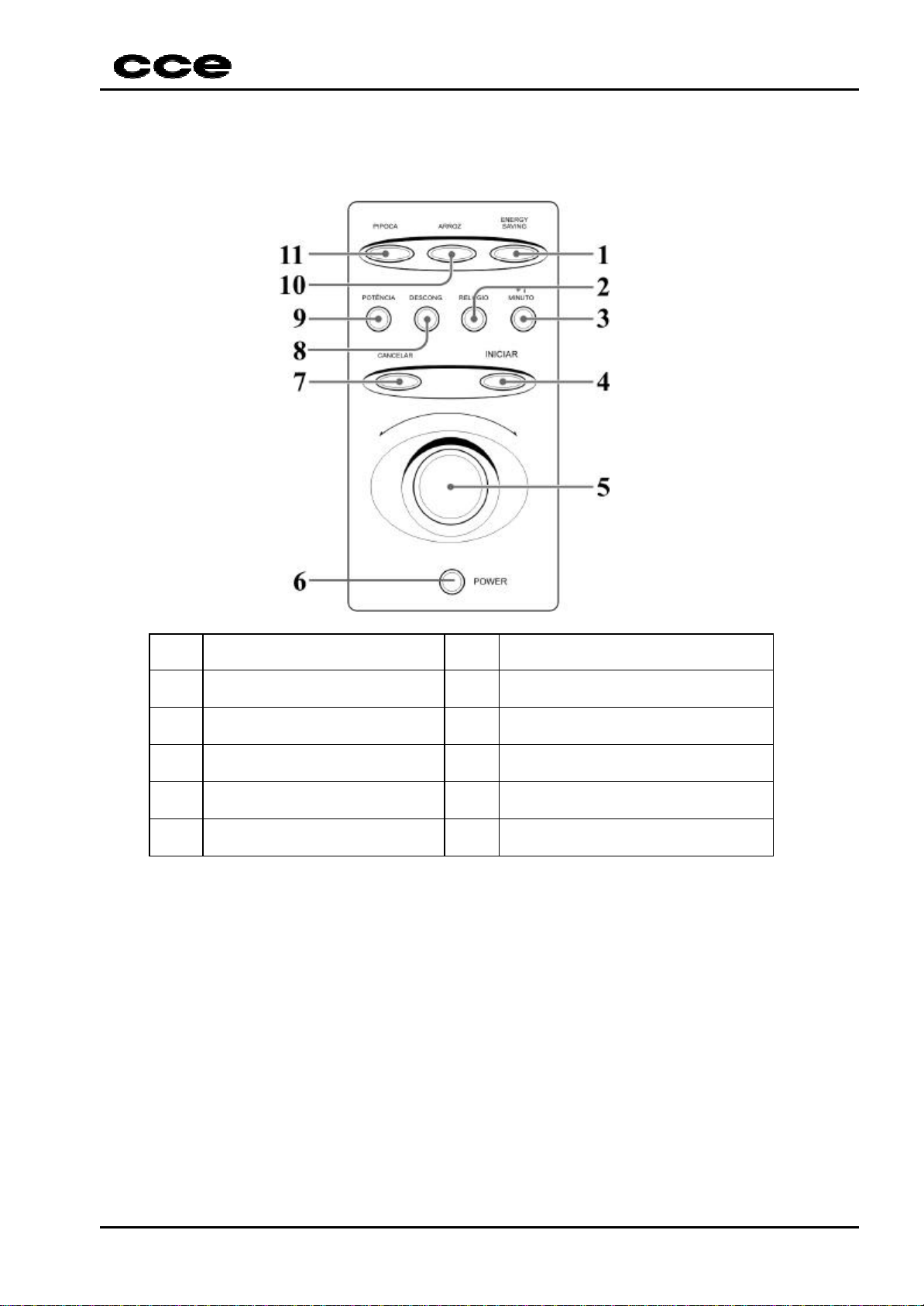
1.1 Panel Description
1 Energy Saving 7 Cancel
2 Clock 8 Defrost
3 +1 minute 9 Power
4 Start 10 Rice
5 Adjustment Switch 11 Pop Corn
6 Power On/Off
Page 4
M-400
3
1.2 Acessories and Parts
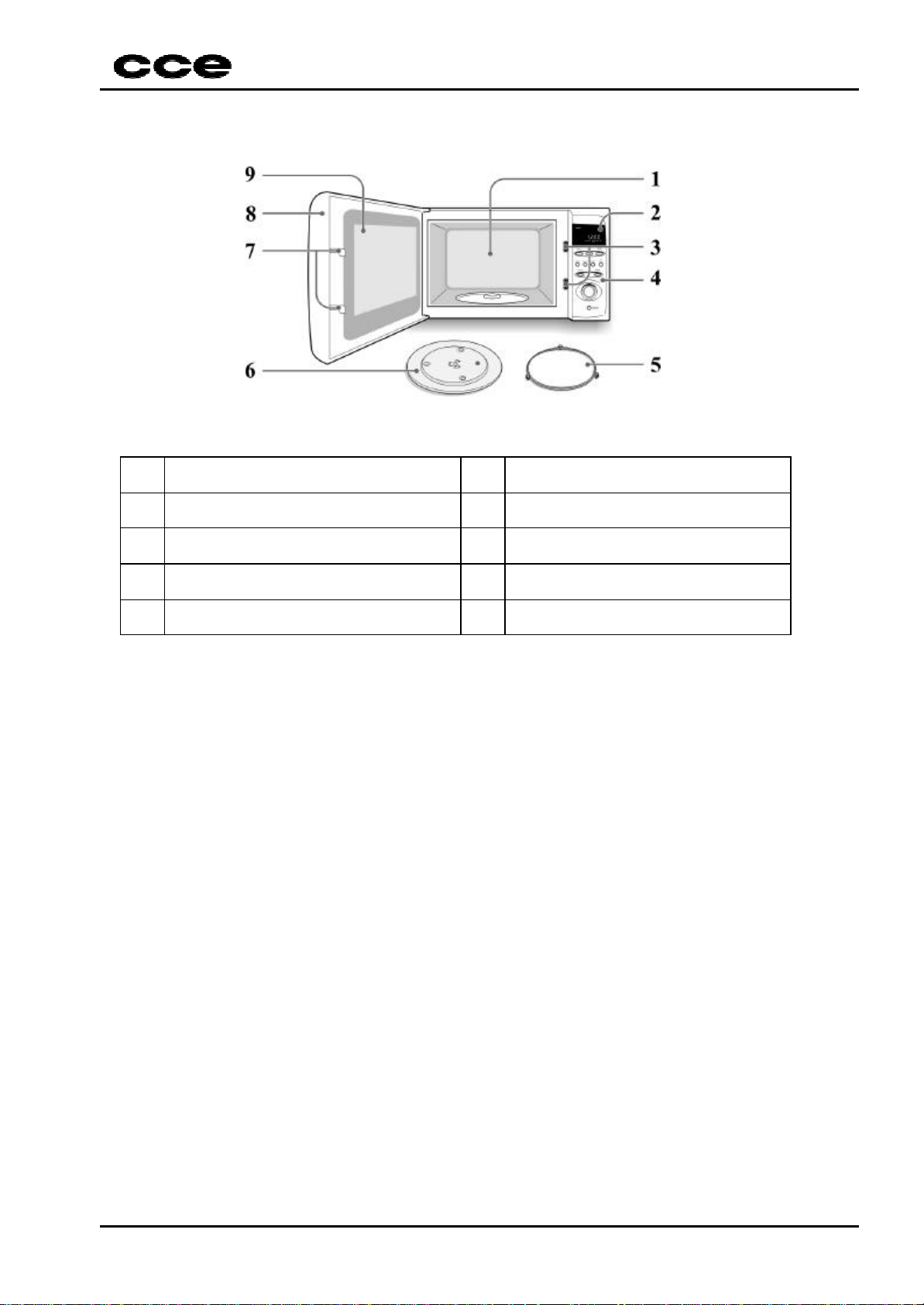
1 Oven Cavity 6 Turntable
2 Digital Display 7
Door′s Security System
3
Door′s lockers
8 Oven Door
4 Control Panel 9 Transparent Screen of the Door
5 Sliding Guide of the Turntable
Page 5
M-400
4
2. TECHNICAL SPECIFICATION
Procedure to check up microwaves parameters
2.1. Product:
Device: Microwaves Oven
Model: M-400.
Capacity: 30 liters
Cavity Frontal Panel - Material: Steel SAE 1010 ZCL Miniatured Crystals
Lateral Panel ( NBR 7008 ).
Back Panel - Weld by projections ( capacitive and resisti ve )
Chassis - Finishing: Painting the to the hot one – Epox.
Cabinet - Color: ABS white euro.
Dimensions: Product
Packing
Weight: Product
Packed Product
Display Led 7 segments.
Clock 12h
Browner
≈ 530X320X430 mm
≈ 612X376X477mm
≈ 15,80 Kg
≈ 18,10Kg
2.2. Specifications:
a) Supply:
Supply voltage: V 120 108 132
Supply Frequency: Hz 60 - -
Microwaves Frequency ( ISM ): MHz 2450 2435 2465
Consumed Power : M-400 W 1450 - Microwaves Power : M-400 W 900 - Browner Power : M-400 W 1050
Nominal Current: M-400 A 13 - -
b) PCB Voltage
Trafo: Primary Vac 120 - -
Secondary Vac 10 - 12V + / - C05 Vdc 14 - 5V + / - C15 Vdc 5 - -
UN. Nominal Min. Max.
V 220 209 231
point UN. Nominal Min. Max.
Vac 220 - -
Page 6
M-400
5
c) High Voltage.
Magnetron voltage KV 4,25 - Filament current A 10 - Diode current mA 300 - -
d) General:
− Resonance frequency ( XTAL ): 8,00MHz;
− Alarm frequency ( Buzzer ): 2,00KHz;
− Duration time of the sonorous alarm when pressed the key: 0,05 second;
− Duration time of the sonorous alarm when finished the process: 0,5 second/3 touches;
− Indication when the electric net: Access 4 segments / two points blink, to indicate that
the pr oduct is power on at the electric net.
2.3. Functions:
01 Energy Saving Cook wiht the 80% power.
02 Clock Clock function 12:00h.
03 +1 more Heat for 1 minute or add + 1 minute for the time.
04 Power on Execute the programed option.
05 Set Set the time and set the clock.
06 Power off / Canc el Stop the work or cancel the programming.
07 Defrost Execute the defrost pre programed function.
08 Power Set the level power desired.
09 Browner Execute durador function.
10 Pop corn Execute the pop corn pre programed function.
11 POWER Master Key
2.4. Safety Requisites:
a) Specification:
Accordance Product: IEC325-2-25 ( 1996 ).
b) Safety divices:
- Fuse of net: 20A/120V
- Monitored microwaves: 1st Monitored key of the door (otice the microcontroler the
- Cavity thermostat : Temperature = 95ºC;
- Magnetron thermostat: Temperature = 135ºC;
10A/220V
door state).
2nd Monitored key of the electric net (em parallel with AC, in
case of relay fail and of the third key in series with electric net,
provoke the fuse bu rning.).
3rd Key in serires with the electric net ( interrupt the circuit
supply at the moment when is opened the door. ).
Page 7
M-400
6
3. TEST INSTRUCTION
3.1. Microwaves creepage
Specification: the microwaves creepage – a distance of 50mm of the external
surface of the device could not exceed 1miliwatts for squared centimeters.
Experience: a (275 +/- 5) g load of potable water at (20 +/- 2) ºC temperature inside a
recipient of thin walls of borosilicate glass with diameter upper 85mm is places at the
horizontal support center, the device supplied with nominal voltage and operated with
controls adjusted to maximim power. The microwaves meter is moved over the device
surface with objective the locate microwaves creepage.
The maximum creepage colud not exceed 1 miliwatts per squared centimeters.
3.2. Output power measurement of microwaves.
It must be utilized borosilicate recipient with external diameter of aproximately
190mm and height of 90mm and thickness of 3mm.
At the begining of the experience, the oven and the recipient must be at
environment temperature. And used to the experince potable water with 10 +/- 1 ºC
initial temperature. The water temperature is measured immediately before to
placed in recipient.
An amount of 1000 +/- 5g of water is added in recipient. The recipient is placed at
plate center of the oven. The device is supplied with nominal voltage at the
adjustment of maximum power. It must be placed the needed time for that the water
reach 20 +/- 2ºC. After the time finishing it leave the recipient and it measured
immediately.
Notas:
ü The water is mixed before your temperature be measured.
ü Device of mixing and measurement must have low capability of heating.
ü Specified power 900 Watts (IEC 705)
The output power of the microwaves is calculated by formulation:
P = (1/T) x [4,187 x Mw x (T2 – T1) + 0,55 x Mc x (T2 – T0)] / T
Where:
P = microwaves output in watts.
Mw = water mass in grammes.
Mc = recipient mass in grammes.
T0 = environment temperature in ºC.
T1 = water initial temperature in ºC.
T2 = water final temperature in ºC.
T = heating time in seconds, excluding the heating time of the magneton filament.
3.3. Input power.
The oven will have to be supplied with nominal voltage and a load of 1 liter of water.
The measured input power could not present deviation more than 60W in relation to
the specified value, A potência de entrada medida não poderá apresentar desvio
maior que 60W em relação ao valor especificado, or either, the speficied value for
consumed power will be:
Consumed power = 1450 + 60W.
Page 8

M-400
7
3.4. Oscillation frequency of the microwaves.
The nominal frequency 2450MHz can vary +/- 15MHz.
3.5. Creepage current and dielectric hardeness.
Inicial experience: Submit a device to a climstic expereince during 72 hours at the
following conditions: 24 hours at the environment temperature and 48 hours a 30 +/2ºC and 93 +/- 2% of relative wetly.
Creepage current
The device creepage current could not exceed 0,5mA for class 01, when submitted
to a 1000V voltage.
3.5.1 Dielectric hardness
It could not occur anything spark ou fail when submitted to sinusoidal voltage of
60Hz frequency, during 1 minute accordance the following description:
- beetwen the body and the poles of the supply cord, 1250V
3.6. Heating.
The device is placed as if was inlaid under of ceiling as the following
specifications.
a) minimum height in relation to device 150mm
b) depht of the ceiling 300mm, from the wall of the corner of experience.
c) minimum length 150mm more than the device width.
d) the device must be supplied with voltage 1,06 time the nominal voltage.
As the microwaves, the device is operated during 9 consutives periods of 10
minutes separated by an rest period of 1 minute.
It was adopted as load 1000g of water at 20ºC temperature. During the rest period,
the door is opened and replaced in the recipient.
During the heating experience, the temperature addition could not
exceed the specified values in the table A.
Measured points A B
1. Internal superior of the oven close of the thermostat cable.
2. Next the motor of the revolving.
3. External lateral of the oven beside the transformer.
4. External central superior of the oven
5. Insulation of white cable next the superior interlock.
6. Insulation of the black grey that come from the transformer primary rolling.
160
60
60
60
65
65
Page 9

M-400
8
3.7. Operation without load.
The microwaves oven must be operated without load during the most
time permitted by timer.
The oven could not suffer no damage. Any device of safety will have
to act.
3.8. Supervision device
To curt-circuit the supervisor device of the door. Supply the device
with nominal voltage with the door closed. The door opening will
provoke the automatic power off of the microwaves generator.
3.9. Protection against electric chock (Miniature standard finger)
The standard finger miniature (figure 101 of the IEC 335 - - 25)
cannot touch live parts when applied without appreciable force in
device parts that are accessible only when the oven is operated in
normal use.
3.10. Cutting parts
The device will not have present cutting partes that can bring risk to
the user during a normal operation or maintans.
3.11. Insulation
Do not have be used as insulation the following materials:
ü wood, cotton, silk, ,commom paper, with staple, hygroscopic.
3.12. Amianthus
Amianthus cannot be used in construction of devices.
3.13. Internal wiring
3.13.1 Internal wiring guide
The internal wiring guide must be smooth and free of cutting parts.
The wiring cannot have contact with wings barbs of cooling or similar.
The metallic orifice must be smooth and corners without tips except if
have bushings.
The wiring must not have contact with mobile parts.
Page 10

M-400
9
3.14. Internal wiring insulation.
The internal wiring insilation must resiste at the voltage experience
applied of 2000V, 60Hz during 15 minutes if have not marking
equivalent to IEC227, IEC245, NBR 13249 and NBR 9374.
3.15. Wire heart identification.
The supply cord of class 01 devices must have a wire heart that
connect the earthing terminal of the device to the earthing terminal of
the electric net.
Page 11

M-400
10
3. MATERIAL LIST
CAPACITORS
CODE DESCRIPTION POSITION
1380471932 ELCO 470UF/10V M 8X11MM C18
1380100524 ELCO 10UF/50V M 5x11mm C22
1380109622 ELCO 1UF/100V M 5x11mm C21
1364104102 C.C.D.Y5V 100KPF>=25V Z C8
1363103601 C.C.D. Y5U 10KPF/500V Z C1
1363103601 C.C.D. Y5U 10KPF/500V Z C2
1363103601 C.C.D. Y5U 10KPF/500V Z C3
1363103601 C.C.D. Y5U 10KPF/500V Z C4
1363103303 C.C.D.Y5U 10KPF>=100V Z C14
1363103303 C.C.D.Y5U 10KPF>=100V Z C20
1363103300 C.C.D. Y5U 10KPF/50V Z C14
1363103300 C.C.D. Y5U 10KPF/50V Z C20
1364104102 C.C.D.Y5V 100KPF>=25V Z C10
1364104102 C.C.D.Y5V 100KPF>=25V Z C6
1360330300 C.C.D.NPO 33PF/50V K C11
1360330300 C.C.D.NPO 33PF/50V K C12
1380101328 ELCO 100UF/25V M 6,3X11MM C9
1291222422 ELCO 2200UF/25V M 16X20MM C5
1364104102 C.C.D.Y5V 100KPF>=25V Z CX/GND
1291222422 ELCO 2200UF/25V M 16X20MM C15
1259995898 CAPACITOR DE ALTA TENSAO 7(B11)
1265224563 C.POLY.M.220KPF/250VAC K SUPX2
RESISTORS
CODE DESCRIPTION POSITION
1183510392 RES.METAL.FILME 1/2W 10K 5% N R12
1183510392 RES.METAL.FILME 1/2W 10K 5% N R17
1183510392 RES.METAL.FILME 1/2W 10K 5% N R57
1183510392 RES.METAL.FILME 1/2W 10K 5% N R58
1183510392 RES.METAL.FILME 1/2W 10K 5% N R59
1183510392 RES.METAL.FILME 1/2W 10K 5% N R6
1183510392 RES.METAL.FILME 1/2W 10K 5% N R60
1183510492 RES.METAL FILME 1/2W 100K 5% N R63
1183522392 RES.METAL FILME 1/2W 22K 5% N R41
1183522392 RES.METAL FILME 1/2W 22K 5% N R61
1183522392 RES.METAL FILME 1/2W 22K 5% N R8
1183510292 RES.METAL FILME 1/2W 1K 5% N R1
1183510292 RES.METAL FILME 1/2W 1K 5% N R21
1183510292 RES.METAL FILME 1/2W 1K 5% N R22
1183510292 RES.METAL FILME 1/2W 1K 5% N R23
1183510292 RES.METAL FILME 1/2W 1K 5% N R24
1183510292 RES.METAL FILME 1/2W 1K 5% N R25
1183510292 RES.METAL FILME 1/2W 1K 5% N R26
1183510292 RES.METAL FILME 1/2W 1K 5% N R27
1183510292 RES.METAL FILME 1/2W 1K 5% N R28
1183510292 RES.METAL FILME 1/2W 1K 5% N R29
1183510292 RES.METAL FILME 1/2W 1K 5% N R50
Page 12

M-400
11
CODE DESCRIPTION POSITION
1183556292 RES.METAL FILME 1/2W 5,6K 5% N R52
1183556292 RES.METAL FILME 1/2W 5,6K 5% N R53
1183556292 RES.METAL FILME 1/2W 5,6K 5% N R54
1183556292 RES.METAL FILME 1/2W 5,6K 5% N R55
1183556292 RES.METAL FILME 1/2W 5,6K 5% N R56
1183547392 RES.METAL.FILME 1/2W 47K 5% N R49
1183547392 RES.METAL.FILME 1/2W 47K 5% N R5
1183547292 RES.METAL FILME 1/2W 4,7K 5% N R13
1183547292 RES.METAL FILME 1/2W 4,7K 5% N R14
1183547292 RES.METAL FILME 1/2W 4,7K 5% N R19
1183547292 RES.METAL FILME 1/2W 4,7K 5% N R4
1183547292 RES.METAL FILME 1/2W 4,7K 5% N R42
1183547292 RES.METAL FILME 1/2W 4,7K 5% N R48
1183547292 RES.METAL FILME 1/2W 4,7K 5% N R62
1183510192 RES.METAL FILME 1/2W 100R 5% N R10
1183522292 RES.METAL FILME 1/2W 2,2K 5% N R11
1183522292 RES.METAL FILME 1/2W 2,2K 5% N R18
1183522292 RES.METAL FILME 1/2W 2,2K 5% N R9
1183533392 RES.METAL FILME 1/2W 33K 5% N R2
1183533392 RES.METAL FILME 1/2W 33K 5% N R3
1183510292 RES.METAL FILME 1/2W 1K 5% N R51
1183510192 RES.METAL FILME 1/2W 100R 5% N R32
1183510192 RES.METAL FILME 1/2W 100R 5% N R33
1183510192 RES.METAL FILME 1/2W 100R 5% N R34
1183510192 RES.METAL FILME 1/2W 100R 5% N R35
1183510192 RES.METAL FILME 1/2W 100R 5% N R36
1183510192 RES.METAL FILME 1/2W 100R 5% N R37
1183510192 RES.METAL FILME 1/2W 100R 5% N R38
1183510192 RES.METAL FILME 1/2W 100R 5% N R39
1183547192 RES.METAL FILME 1/2W 470R 5% N R20
1183547192 RES.METAL FILME 1/2W 470R 5% N R30
1182510632 RES.CARBONO 1/4W 10M 5% N R40
DIODES
CODE DESCRIPTION POSITION
1414621902 DIODO 1N4148 75V SINAL D8
1415180901 DIODO RETIFICADOR SK107 D1
1415180901 DIODO RETIFICADOR SK107 D2
1415180901 DIODO RETIFICADOR SK107 D3
1415180901 DIODO RETIFICADOR SK107 D4
1415180901 DIODO RETIFICADOR SK107 D5
1415180901 DIODO RETIFICADOR SK107 D7
1410430015 DIODO RETIFICADOR 1N4004 D1
1410430015 DIODO RETIFICADOR 1N4004 D2
1410430015 DIODO RETIFICADOR 1N4004 D3
1410430015 DIODO RETIFICADOR 1N4004 D4
1410430015 DIODO RETIFICADOR 1N4004 D5
1410430015 DIODO RETIFICADOR 1N4004 D7
1415172201 DIODO UF-4004 D1
1415172201 DIODO UF-4004 D2
Page 13

M-400
12
CODE DESCRIPTION POSITION
1415172201 DIODO UF-4004 D3
1415172201 DIODO UF-4004 D4
1415172201 DIODO UF-4004 D5
1415172201 DIODO UF-4004 D7
1410430015 DIODO RETIFICADOR 1N4004 D1
1410430015 DIODO RETIFICADOR 1N4004 D2
1410430015 DIODO RETIFICADOR 1N4004 D3
1410430015 DIODO RETIFICADOR 1N4004 D4
1410430015 DIODO RETIFICADOR 1N4004 D5
1410430015 DIODO RETIFICADOR 1N4004 D7
1410440015 DIODO 1N-4005 RETIFICADOR D1
1410440015 DIODO 1N-4005 RETIFICADOR D2
1410440015 DIODO 1N-4005 RETIFICADOR D3
1410440015 DIODO 1N-4005 RETIFICADOR D4
1410440015 DIODO 1N-4005 RETIFICADOR D5
1410440015 DIODO 1N-4005 RETIFICADOR D7
1415172101 DIODO UF-4005 D1
1415172101 DIODO UF-4005 D2
1415172101 DIODO UF-4005 D3
1415172101 DIODO UF-4005 D4
1415172101 DIODO UF-4005 D5
1415172101 DIODO UF-4005 D7
1414621902 DIODO 1N4148 75V SINAL D10
1414621902 DIODO 1N4148 75V SINAL D9
1127613200 DIODO ALTA TENSAO ESJC13-12BX
TRANSISTORS AND IC´s
CODE DESCRIPTION POSITION
1320020102 TRANSISTOR BC-547B Q1
1320020102 TRANSISTOR BC-547B Q11
1320020102 TRANSISTOR BC-547B Q12
1320020102 TRANSISTOR BC-547B Q13
1320020102 TRANSISTOR BC-547B Q14
1320020102 TRANSISTOR BC-547B Q15
1320020102 TRANSISTOR BC-547B Q16
1320020102 TRANSISTOR BC-547B Q17
1320020102 TRANSISTOR BC-547B Q2
1320020102 TRANSISTOR BC-547B Q3
1320020102 TRANSISTOR BC-547B Q5
1320020102 TRANSISTOR BC-547B Q7
1320020102 TRANSISTOR BC-547B Q8
1149376899 I.C. 7805 (PLASTICO) IC1
1146100353 I.C. 7805 (METAL) IC1
1711000103 I.C. GRAVADO 1711000000 IC2
1711000003 I.C. SOFT V1.0 (MC68HC908JL3)
1711000000 I.C.OTP MC68HC908JL3CDW
1710100091 I.C. OTP MC68HC908JL3
Page 14

M-400
13
SWITCH
CODE DESCRIPTION POSITION
1449009600 CHAVE DE TOQUE 4,3MM 260g SW1
1449009600 CHAVE DE TOQUE 4,3MM 260g SW2
1449009600 CHAVE DE TOQUE 4,3MM 260g SW3
1449009600 CHAVE DE TOQUE 4,3MM 260g SW4
1449009600 CHAVE DE TOQUE 4,3MM 260g SW5
1449009600 CHAVE DE TOQUE 4,3MM 260g SW6
1449009600 CHAVE DE TOQUE 4,3MM 260g SW7
1449009600 CHAVE DE TOQUE 4,3MM 260g SW8
1449009600 CHAVE DE TOQUE 4,3MM 260g SW9
1449009500 CHAVE DE TOQUE 4,3MM 260g SW1
1449009500 CHAVE DE TOQUE 4,3MM 260g SW2
1449009500 CHAVE DE TOQUE 4,3MM 260g SW3
1449009500 CHAVE DE TOQUE 4,3MM 260g SW4
1449009500 CHAVE DE TOQUE 4,3MM 260g SW5
1449009500 CHAVE DE TOQUE 4,3MM 260g SW6
1449009500 CHAVE DE TOQUE 4,3MM 260g SW7
1449009500 CHAVE DE TOQUE 4,3MM 260g SW8
1449009500 CHAVE DE TOQUE 4,3MM 260g SW9
1449009800 MICRO CHAVE 29(2G7)
1449008200 CHAVE MICRO 533A 29(2G7)
ACESSORIES AND DIVERSE
CODE DESCRIPTION POSITION
1677236001 CJT.PAINEL CONTROLES 39(G3)
1027236001 CJT.PCI MANUAL/MONTADO
1027236011 CJT.PCI IA/SMD MONTADO
1107220431 PCI PRINCIPAL (4PCS)
1160300347 CABO FRAY 300V 24AWG PR 60MM DE:C15(+)P/R12
1777220415 PLACA ISOLANTE
1631028604 BASE CONECTORA 04VIAS CN01
1347220501 TRAFO DE FORCA 220V TF1/5(F11)
1397211603 RELE 12V RL3
1397211602 RELE 12V RL3
1397211601 RELE OMIF-S-112LM RL1
1129305299 VARISTOR TNR-15G 471K
1511302600 BUZZER BZ1
1404004400 DISPLAY DL1
1404003700 DISPLAY DL1
1425011700 CRISTAL 8,000MHZ HC-49U X1
1442903024 ENCODER ROTATIVO EN01
1677227701 PAINEL DE CONTROLE
1677235801 VISOR DO DISPLAY
1677220408 KNOB MULTI JOG
1600005120 PAR.AA.PAN.PH.PP1 3,0X10 ZNA 34(9G5)
1677220416 MASCARA DO PAINEL
1876306800 ADESIVO JET-MELT
1647660500 CABO MONT.22AWG 2V AZ 395MM
1647661300 CABO FRAY 2,54 07V 24AWG 65MM
1657220403 BLINDAGEM
Page 15

M-400
14
CODE DESCRIPTION POSITION
1537215505 TERMOSTATO MAGNETRON P135-120 17(D10)
1537215502 TERMOSTATO MAGNETROM P135-120 17(D10)
1537215504 TERMOSTATO CAVIDADE P95-80 41(A8)
1537215501 TERMOSTATO P/CAVIDADE P95-80 41(A8)
1461359402 FUS.ACAO RET.3AG 10A/250V 37(G8)
1027235880 CABO FLEX.A.T.18AWG C/DIODO MT
1537211601 MAGNETRON 15(D10)
1537211609 PRATO 49(C6)
1537220501 MOTOR DO VENTILADOR 220V
1537211605 MOTOR DO VENTILADOR 220V
1347220502 CJT.TRAFO ALTA TENSAO 220V
1347222601 CJT.TRAFO ALTA TENSAO 220V
1457103400 LAMPADA 220V 25W 33(F6)
1747235801 PORTA FUSIVEL 35(G8)
1747211601 PORTA FUSIVEL 35(G8)
1537211603 MOTOR DO PRATO 220V 47(E6)
1850473502 FILME PORTA 283X149X0,2TR.ADES 48(E6)
1449009900 MICRO CHAVE 30(G6)
1449008100 CHAVE MICRO 532A 30(G6)
1777220411 SUPORTE DO PRATO 52(D7)
1537220403 CAVIDADE MONTADA 110/220V 12(B7)
1697220402 CHASSI
1838290492 ACO C.1010 ZCHDZ0,65 385X852ZQ
1677220401 PAINEL SUPERIOR 2(F8)
1838290392 ACO C.1010 ZCHDZ0,65 400X400ZQ
1677220402 PAINEL FRONTAL
1838290592 ACO C.1010 ZCHDZ0,65 350X570ZQ
1677220403 PAINEL TRASEIRO
1838290292 ACO C.1010 ZCHDZ0,65 365X580ZQ
1727211605 SUPORTE DO MOTOR DO PRATO
1830029992 ACO C.LF EEP0,61 128,5BOB P.ZN
1727220402 GUIA DE ONDAS
1838290692 ACO C.1010ZC HDZ0,65X185X255ZQ
1727220403 SUPORTE DO MAGNETRON
1838691190 ACO C.1010 ZCHDZ 0,95 170X3 ZQ
1873363000 TINTA EPOXI EM PO BRANCA
1677220411 PORTA METALICA MONTADA 9(F4)
1677220404 PORTA METALICA
1838390792 ACO C.1010ZC HDZ0,80X400X530ZQ
1727220411 CJT.SUPORTE DA DOBRAD.INF/SUP
1727220404 SUPORTE DA DOBRADICA INF/SUP
1838591090 ACO C.LQ E2MM 320MMX2MT Z.BRI
1727220407 PINO DA DOBRADICA
1873368600 TINTA EPOXI PRETO
1597220401 TAMPA INFERIOR 1(E9)
1830209921 ACO CARB.1010 ESP.0,80 376X574
1657220401 DOBRADICA INFERIOR 2(F8)
1657220404 DOBRADICA INFERIOR
1838490892 ACO C.LQ ESP3MM 90MMX3MT Z.BRI
1657220402 DOBRADICA SUPERIOR 43(A5)
Page 16

M-400
15
CODE DESCRIPTION POSITION
1657220405 DOBRADICA SUPERIOR
1838490990 ACO C.LQ E3MM 150MMX3MT ZI.BRI
1777220402 SUPORTE DAS MICRO CHAVES 31(G6)
1777220401 ACIONADOR DAS MICRO CHAVES 27(G7)
1777220403 TRAVA DA PORTA 16(E5)
1687220401 MOLA DA TRAVA DA PORTA 20(F5)
1777220404 SUPORTE DO VENTILADOR 21(C11)
1777211610 HELICE 24(C11)
1777220406 ARO DA PORTA 46(E6)
1677220406 PAINEL DA PORTA 53(F3)
1677225903 VISOR DA PORTA 56(E3)
1677235803 EMBLEMA CCE
1777220412 CJT.GUIA DOS ROLETES 54(E3)
1727211602 CINTA DO CAPACITOR 8(C11)
1830118912 ACO C.LF EP0,76 153XBOB P.ZN
1777220409 PE DE APOIO 32(2G11)
1057234602 CALCO DE PAPELAO 3X16,5
1057220498 CJT.CALCO PROT.PRATO ESQ/DIR
1057220499 CJT.CALCO PROT.SUP/INF/DIR/ESQ
1057235801 CAIXA DE EMBALAGEM
1727220405 GABINETE SUPERIOR 55(B1)
1838791292 ACO C.LF R.ZIN0,5 410X1160 ZQ
1600015112 PAR.AA.P.PH.PP1 4,0X12 ZNA RES 14(2D9.2C12)
1600015120 PAR.AA.P.PH.PP1 3,0X10 ZNA RES 18(2C9)
1600214027 PAR.AA.LEN.TRUSS PH.AB4X10ZNA 38(4A3.F7.6G9)
1600062112 P.AALEN.TR.PH.AB4X12 ZNA 22(A9)
1600016107 PAR.AA.P.PH.BEMLI3,0X 8ZNA RES 45(4E11)
1600214027 PAR.AA.LEN.TRUSS PH.AB4X10ZNA 28(B4)
1600038140 P.M.SEXT.PH.4X16ZNA C/ARR PRES 3(2B5.2G8)
1600615033 PAR.AA.SEX.PH.B5X12ZNA AR.FIX 6(4G10)
1600004118 PAR.A.A.PAN.PH. AB4,0X10 ZNA 42(2F6)
1600003115 PAR.A.A.PAN.PH.B 4,0X25 ZNA 50(2C11)
1760609401 ARRUELA NYLON 13,5X20X0,5 51(D7)
1888250100 PANO P/LIMPEZA BR
1889401800 FITA A.ADES.S/LOG L=38X100MT
1769900019 SACO PLASTICO 120X100X0,05 AD
1850021502 FILME POLIETILENO 350X400X0,02
1067235802 MANUAL DE INSTRUÇOES M-400
1067236001 ETIQUETA DE IDENTIFICAÇAO 220V
1069100073 FOLHETO OFICINAS AUTORIZADAS
1069100070 FOLHETO OFICINAS AUTORIZADAS
1068126600 ETIQ.ALERTA P/CABO FORCA 220V
1068126400 ETIQ.COD.BARRAS 50X86
1889500900 PAPEL DE SEDA
1644507200 CABO FORCA 2X1,5X1280 P.CHATO 40(A11)
1647657100 FIO TERRA 1X1,20MT C/TERMINAL
1889801400 RIBBON WAX CERA
1878504000 GRAXA MO-2000
1069100071 CERTIFICADO DE GARANTIA
1057222304 CALCO VINCADO
Page 17

M-400
16
CODE DESCRIPTION POSITION
1873368600 TINTA EPOXI PRETO
1647660600 CABO FLEX.A.T.18AWG 1V 130MM
1873363000 TINTA EPOXI EM PO BRANCA
1647660700 CABO FLEX.A.T.18AWG 1V 310MM
1647678900 CJT.CABO MONTADO
1610008104 PORCA ESP.SEX.4,0 ZNA C/FLANGE 4(2E9.2A5)
1761502800 ESPUMA AMORTECEDORA 26(G11)
1761502900 ESPUMA DO MAGNETRON 19(B2)
1600061121 PAR.AA.LEN.TR.B4X8 AR.ESTR.ZNA 25(F10.F11)
1600015120 PAR.AA.P.PH.PP1 3,0X10 ZNA RES 18(G8)
1600007106 PAR.AA.PAN.PH.BEMLI3,0X6 ZNA 44(2D10)
1600015112 PAR.AA.P.PH.PP1 4,0X12 ZNA RES 14(C10)
1606414027 P.AA.PH.LENT.AB4X10ARR ZNA EST 28(B11)
1876301600 TRAVA QUIMICA P/PARAFUSO
1440090046 CHAVE DE PRESSAO 1UNIDADE
1677227703 TECLA POWER
1068127201 ETIQ.ADES.N.SERIE C/5
1577220401 TAMPA SAIDA DE ONDAS
1610001116 ARR.FE LISA 22,5X6,5X1,2 ZNA FIX.TRAFO
Page 18

M-400
17
4. ELECTRICAL SCHEME
4.1 MAIN PCB
5. SILKTOP AND SOLDERS
5.1 MAIN PCB
6. EXPLODED VIEW
Page 19

PCI TRAFO/RELEPCI TRAFO/RELE
12V12V
REDEREDE
FUSIVELFUSIVEL
PROTECAOPROTECAO
TERMICA DATERMICA DA
CAVIDADECAVIDADE
PCI TRAFO/RELEPCI TRAFO/RELE
opcionalopcional
CN01CN01
**
TF01TF01
F2F2
PROTECAOPROTECAO
TERMOSTATOTERMOSTATOTERMICA DOTERMICA DO
F1F1
SW-REDESW-REDE
F1F1
F2F2
11
VRS1VRS1
220V-TNG475220V-TNG475
22
120V-TNG275120V-TNG275
**
33
11
R44R44
BC547BC547
R46R46
10K10K
R43R43
Q9Q9
10K10K
D11D11
BZV55F3V3BZV55F3V3
R47R47
10K10K
R45R45
150R150R 22K22K
Q01Q01
BC547BC547
+5V+5V+5V+5V
R51R51
5K65K6
12V12V
33
D01D01D03D03
D02D02D04D04
C05C05 C06C06
44
1000u/25V1000u/25V
100kpF100kpF
CN02/2CN02/2
CN02/4CN02/4
LM7805-CVLM7805-CV
CN03/2CN03/2
41461003534146100353
CN03/4CN03/4
1N41481N4148
D08D08
IC01IC01
GNDGND
OUT OUT ININ
10kpF10kpF
C14C14
C15C15
47OuF/10V47OuF/10V
R03R03
33k33k
R02R02
33k33k
Q10Q10
BC547BC547
+5V+5V
R42R42
C18C18
+5V+5V
EN01EN01
ENCODERENCODER
R01R01
1K1K
R42R42
10K10K
4k74k7
BZ1BZ1
CN02/1CN02/1
+5V+5V
CN03/1CN03/1
C18C18
1uF/50V1uF/50V
470uF/50V470uF/50V
R58R58
10K10K
R49R49
47k47k
R59R59
10K10K
R48R48
4k74k7
Q11Q11
BC547BBC547B
R20R20
470470
R21R21
1k1k
R22R22
1k1k
M.AQUECM.AQUEC
R23R23
1k1k
AQUECAQUEC
R24R24
R25R25
1k1k
1k1k
SW01 - LIGARSW01 - LIGAR
SW02 - DESL./CANC.SW02 - DESL./CANC.
SW03 - DESCONG.SW03 - DESCONG.
SW04 - POTENCIASW04 - POTENCIA
SW05 - RELOGIOSW05 - RELOGIO
SW06 - +1minSW06 - +1min
SW07 - PIPOCASW07 - PIPOCA
SW08 - AQUECERSW08 - AQUECER
SW09 - M.AQUEC.SW09 - M.AQUEC.
R26R26
1k1k
POT.POT.
R27R27
1k1k
RELOGRELOGDESCONG.DESCONG. DESLG.DESLG.
+1 min+1 min
+5V+5V
R31R31
1010
R30R30R29R29R28R28
4704701k1k1k1k
LIGARLIGARPIPOCAPIPOCA
C9C9 C10C10
100u100u 100n100n
CHAVE REDECHAVE REDE
VENTILADORVENTILADORPRATOPRATOLAMPADALAMPADA
PARALELAPARALELA
RESISTENCIA BLINDADARESISTENCIA BLINDADA
1050 W 1050 W
CN03/3CN03/3
CN02/3CN02/3
22
LAMPADALAMPADA
RL-03RL-03
RL02RL02
12V12V
D07D07
1N40021N4002
+5V+5V +5V+5V
CN03/7CN03/7
CN02/7CN02/7
CN03/6CN03/6
CN02/6CN02/6
Q03Q03
BC547BC547
Q04Q04
BC547BC547
R15R15
2k22k2
R11R11
22K22K
Q8Q8
BC5447BC5447
R13R13
4K74K7
R41R41
22k22k
R16R16
4K74K7
R4R4
4K74K7
R12R12
10k10k
+5V+5V
R14R14
10k10k
+5V+5V
R9R9
2k22k2
10K10K
R52R52
10K10K
R53R53
28282727262625252424232322222121202019191818171716161515
10K10K
RSTRST
PTA5PTA5
PTD5PTD5
PTD4PTD4
PTA4PTA4
PTD2PTD2
PTB0PTB0
PTD3PTD3
PTD1PTD1
PTB1PTB1
PTB3PTB3
PTB2PTB2
PTB4PTB4
PTD0PTD0
MC68HC908JL3MC68HC908JL3
Q06Q06
BC547BC547
R07R07
22k22k
+5V+5V
R10R10
100R100R
IRQ1IRQ1
VSSVSS
PTA0PTA0
PTA6PTA6
OSC1OSC1
VDDVDD
PTA1PTA1
PTA2PTA2
PTB7PTB7
PTA3PTA3
PTB5PTB5
PTB6PTB6
PTD6PTD6
PTD7PTD7
14141313121211111010998877665544332211
10K10K
R55R55
BROWNERBROWNER
D06D06
1N40021N4002
+5V+5V
Q12Q12
BC547BC547
DL01DL01
11
Q13Q13
BC547BC547
22
Q14Q14R54R54
BC547BC547
44
Q15Q15
BC547BC547
CAPACITORCAPACITOR
ALTA TENSAOALTA TENSAO
IC02IC02
RL01RL01
12V12V
CN03/5CN03/5
CN02/5CN02/5
Q05Q05
BC547BC547
R17R17
10k10k
10K10K
66
C21C21
1uF/50V1uF/50V
R56R56
Q16Q16
BC547BC547
88
R18R18
2k22k2
Q07Q07
BC547BC547
R08R08
22k22k
MAGNETRONMAGNETRON
D05D05
1N40021N4002
12V12V
+5V+5V
R57R57
10k10k
CHAVE PROTECAOCHAVE PROTECAO
ALTA TENSAOALTA TENSAO
TRANSFORMADORTRANSFORMADOR
CN04CN04
11
22
C20C20
10kpF10kpF
R50R50
1k1k
Q02Q02
BC547BC547
R19R19
4K74K7
R05R05
47k47k
R06R06
10k10k
D09D09
1N41481N4148
C22C22
10uF/50V10uF/50V
D10D10
1N41481N4148
C08C08
10kpF10kpF
R40R40
10K10K
C11C11
1OpF1OpF
+5V+5V
R32R32
150R150R
R33R33
150R150R
R34R34
150R150R
R35R35
150R150R
R36R36
150R150R
1616
1515
1414
1313
1111
(B)(B)
(G)(G)
(A)(A)
(C)(C)
(F)(F)
R37R37
150R150R
33
(D)(D)
MAGNETRONMAGNETRON
DIODODIODO
ALTA TENSAOALTA TENSAO
P/ CHAVE MONITORAP/ CHAVE MONITORA
MONITORAMONITORA
PORTA FECHADAPORTA FECHADA
11
22
R38R38
150R150R
R39R39
150R150R
55
(E)(E)
(DP)(DP)77
BB
AA
DES.DES.
PROJ.PROJ.
APRO.APRO.
EMAILEMAIL
EMAILEMAIL
P.A.P.A.ALT.ALT.
NOMENOME
SCHUMACHERSCHUMACHER
SCHUMACHERSCHUMACHER
WALTERWALTER
ACRESC.MOD.:M-3010 / M-400ACRESC.MOD.:M-3010 / M-400
ACRESC.MOD.:M300/CASSINO/TOK LINE E CH REDEACRESC.MOD.:M300/CASSINO/TOK LINE E CH REDE
DISCRIMINACAODISCRIMINACAO
TITULO:TITULO:
ESQUEMA ELETRICOESQUEMA ELETRICO
DATADATA
14.12.9914.12.99
14.12.9914.12.99
14.12.9914.12.99
MOD.MOD.
MW-2000MW-2000
COD.COD.
SHUMSHUM
SHUMSHUM
N.N.
A1A1
1.00.72204.011.00.72204.01
27/01/0327/01/03
25/06/0125/06/01
DATADATAVISTOVISTO
Page 20

JE01
TF01
VRS1
RL03
CN01
1
ENT.AC
BROWNER
RL02
3
RL01
MAGNETRON
LAMPADA
D01
D5
Q1
R20
C01
D02
C13
R24
R25
R26
JA05
R2
C7
EBC
CN04
C9
R33
Q10
C
B
E
JB02
DL01
D03
JC04
R23
C25
R3
R4
JA04
R22
D04
7805
IC03
S C E
RA01
R19
R13
R10
R7
C24
C19
12
11
C10
R21
R34
R32
Q9
Q11
C
C
B
B
E
E
8 4 1
9
R55
C03
C02
M-304/M-308
+12V
REF.AC
+12V
R29
R28
Q18
GND
GND
R12
R11
R15
D11
R48
Q17
R56
BROW.
REF.AC
BROW.
JC03
R14
EBC
EBC
R5
EBC
Q8
C
B
E
EBC
E
B
C
R52
R53
D06D07
CN02
MAG.
LAMP.
7
7
JB01
MAG.
LAMP.
Q4
R8
Q3
72223.01
Q2
R45R46
R47
R49
E
B
Q14
C
Q15
Q16
R51
C
B
E
R57
D12
D13
D14
C04
C5
CN05
11 1
R35
JC05
JH01
22
1
C12
EBC
1613
D08
JE02
R30
R17
D9
C16
C17
JA02
23
44
C26
33
C27
34
C22
C11
X1
C21
R27
R31
R36
C
B
E
Q13
Q12
R43
R44
D10
R18
R16
R9
R6
R54
JC08
JC01
R50
JA01
JC06
C20
1
BZ01
CN03
1
EBC
EBC
E
B
C
R1
JA03
C23
C18
BUZZER
BUZZER
Q7
EBC
Q19
JC07
R37
R38
R39
R40
R41
R42
Q6
Q5
C
B
E
NOME
DES.
PROJ.
APRO.
TÍTULO:
DATA MAT.
15/08/00
15/08/00
15/08/00
ACAB.
ESC.
MOD.
MAIN PCB
M-400
TOL.
PROJEÇÃO
dimensões em mm
N.º
Page 21

D14
Q18
R55
DL01
Q10
Q11
E
E
C
C
R34
R33
C9
R22
CN04
R20
R4
Q1
E
C
R03
R02
C07
D5
R25
R26
R23
R24
R32
R21
C10
C19
12
C25
RA01
CN05
Q12
Q9
E
E
C
R35
C12
1
C24
R07
R10
R13
R19
Q13
C
E
C
R36
R31
C20
R27
X1
R54
C21
C11
C22
34
C27
C26
IC01
23
R06
R09
R16
R18
C
E
C17
E
D10
C16
E
D09
R17
R50
E
R44
R43
C
R53
R42
R41
R40
R39
R38
R37
C18
C23
R28
R29
R01
Q19
R11
C
Q05
R15
C
Q06
R12
E
C
D13
D12
R52
R56
C
E
R48
D11
E
R05
E
R08
E
R14
Q07
R57
E
R51
Q17
C
Q16
E
C
Q15
C
Q14
E
R49
R46
R47
R45
E
Q08
C
C
Q02
C
Q03
C
Q04
D1
TÍTULO:
1
IC03
BZ01
C13
C5
D4
D3
D2
C2
C1
C4
C3
1
R30
D8
D7
7
CN03
CN02
7
D6
RL01
RL03
RL02
TF01
CN01
VRS1
MAIN PCB
PROJEÇÃO
dimensões em mm
NOME
DES.
PROJ.
APRO.
DATA MAT.
15/08/00
15/08/00
15/08/00
ACAB.
ESC.
MOD.
M-400
TOL.
N.º
Page 22

 Loading...