

Page 1

Service Manual
Model HPS-1478
Customer: Makro
CODE: 1.01.72451.54
_____________________
Approved Signature
Page 2

HPS-1478
INDEX
1. PRODUCT SPECIFICATION
2. PACKAGING BOX
3. TECHNICAL SPECIFICATION
4. CALIBRATION SCRIPT
5. MATERIAL LIST
6. ELECTRICAL SCHEME
6.1 MAIN AND REMOTE CONTROL PCB
7. SILKTOP AND SOLDERS
7.1 MAIN PCB
7.2 REMOTE CONTROL PCB
8. EXPLODED VIEW
9. BLOCK DIAGRAM
Page 3
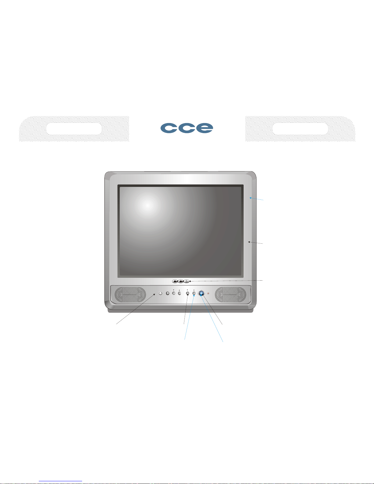
GABINETE FRONTAL
MEC 1.57.72451.02
INJ 1.67.72451.01
ACAB 1.67.72451.02
TECLADO FUNÇÕES
MEC 1.77.72411.06
INJ 1.67.72411.09
ACAB 1.67.72411.10
TECLA POWER
MEC 1.67.72411.03
INJ 1.67.72411.01
ACAB 1.67.72411.02
ESCALA
1:3
FOLHA
2/4
HPS-1478
GABINETE FRONTAL
ABS R PR
1.86.90200.90
PS HI 478 DOW + CZ MÉDIO OPCIONAL
1.86.02063.99 + 1.86.96123.08
EMBLEMA CCE
1.67.72369.04
SENSOR
ON OFF
VOL
CH
MENU
PINTURA
PRATA CRISTAL
1.87.33801.29
IMPRESSÃO
BRANCO
1.87.33701.28
TECLA POWER
SAN AZUL MARINHO
1.86.91604.60
PINTURA
PRATA MEDIUM
1.87.33801.17
TECLADO FUNÇÕES
ABS CZ
1.86.90014.08
IMPRESSÃO
PRETO
1.87.33701.50
Page 4
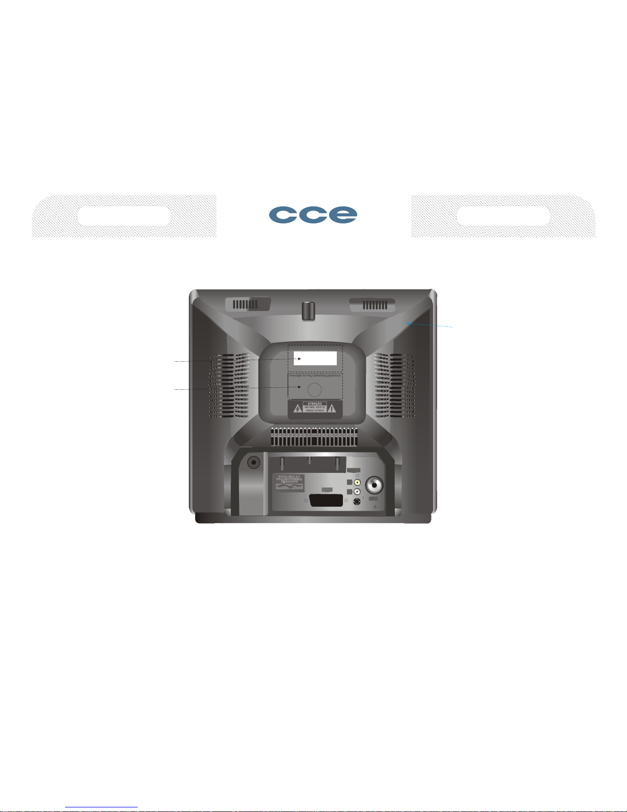
GABINETE TRASEIRO
MEC 1.57.72411.02
INJ 1.57.72411.09
INJ 1.57.72411.05 OPCIONAL
ETIQUETA IDENTIFICAÇÃO
ACAB 1.06.72451.04
GABINETE TRASEIRO
PS HI PRETO
ETIQUETA
IDENTIFICAÇÃO
ESCALA
1:3
FOLHA
3/4
HPS-1478
CONHEÇA A AMAZÔNIA
CONHEÇA A AMAZÔNIACONHEÇA A AMAZÔNIA
PRODUZIDO NO
PÓLO INDUSTRIAL
DE MANAUS
A
(MONO)
L
R
AV 1 IN
V
ATENCIÓNATENCIÓN
CAUTIONCAUTION
NO ABRA, RIESGO DE CHOQUE ELÉCTRICO.NO ABRA, RIESGO DE CHOQUE ELÉCTRICO.
RISK OF ELECTRIC SHOCK. DO NOT OPEN.RISK OF ELECTRIC SHOCK. DO NOT OPEN.
EXT 1
ANT
75
UHF/VHF
CONHEÇA A AMAZÔNIA
ETIQUETA
Nº SÉRIE
Page 5

RC-206
ESCALA
1:1
FOLHA
4/4
GABINETE SUPERIOR
MEC 1.57.72254.05
INJ 1.57.72411.03
ACAB 1.57.72411.04
GABINETE INFERIOR
MEC 1.57.52181.04
ACAB 1.57.72254.08
TAMPA PORTA PILHAS
MEC 1.57.52181.05
ACAB 1.57.72254.09
TECLADO DE BORRACHA
ACAB 1.77.72357.02
IMPRESSÃO
BRANCO
1.87.33701.28
GABINETE SUPERIOR
GABINETE INFERIOR
TAMPA P/ PILHAS
ABS A.F. CZ
1.86.90011.08
ABS A.F. CZ PH OPCIONAL
1.86.90020.08
P.SKIPP.SKIP
P.CHANNELP.CHANN EL
OSD/OUTOSD/OUT
MENUMENU
AVAV
TIMERTIMER
DSCDSC
CCCC
AUTO IMAGEAUTO IMAGE
ON/OFFON/OFF
MUTEMUTE
SLEEPSLEEP
RC-206RC-206
11
44
77
22
55
88
00
33
66
9 9
CH+CH+
VOL+VOL+VOL-VOL-
CH- CH-
Page 6

Page 7

HPS-1478
3. TECHNICAL SPECIFICATION
Procedure to check up color TV electrical parameters
3.1 Audio
3.1.1 Output power at 10% THD
1st method: antenna input connection
a) TV setup in “PP” condition (frequency and channel factory defined).
b) Apply 60dBµV signal to antenna input, modulated with white pattern in 88%
and audio signal with 1kHz frequency modulated in FM with ± 25kHz
deviation.
c) Connect to the audio power amplifier output a resistive load with equivalent
Ohm value of speaker used on the tested TV.
d) Connect a AC Voltmeter/Distortion Meter to the resistive load and increase
volume control until Distortion Meter reading be 10%.
e) Measure voltage on the resistive load and calculate power through next
equation:
P = (V²/R)
Where “V” is voltage in VOLTS, “R” is resistive load in OHMS e “P” is power
in WATTS.
2nd method: connection through external video and audio input
a) TV setup in “PP” condition.
b) Connect a color bar generator (PAL-M system) to video input.
c) Connect an audio generator with 500mVAC level and 400Hz sinusoidal
frequency to audio input.
d) Connect to the power amplifier output a resistive load with equivalent Ohm
value of speaker used on the tested TV.
e) Connect a AC Voltmeter/Distortion Meter to the resistive load and increase
volume control until Distortion Meter reading be 10%. Measure voltage on
the resistive load and calculate power through next equation:
P = (V²/R)
Where “V” is voltage in VOLTS, “R” is resistive load in OHMS and “P ” is power
in WATTS.
Minimum Nominal Maximum Unit
2.00 2.90 - W
3.1.2 Audio Residual
a) TV setup in “PP” condition.
b) Apply 60dBµV signal (frequency and channel factory defined) to antenna
input modulated with white pattern at 88% and audio signal with 1kHz
frequency modulated in FM with 25kHz de viation.
Page 8
HPS-1478
c) Connect an oscilloscope to power amplifier output (connect for the
speaker).
d) Adjust volume to minimum.
e) Use the oscilloscope to measure peak-to-peak voltage, in Volt peak-to-peak
(Vpp).
Minimum Nominal Maximum Unit
- 25 500 mVpp
3.1.3 Audio frequency response in TV’s without tone control
a) TV setup in “PP” condition.
b) Connect a color bar generator (PAL-M system) to video-in.
c) Connect to the audio input TV - an audio generator adjusts to 500 mVac
level, and sine wave 1kHz.
d) Connect to the output power amplifier a resistive load with the same value
of the impedance speaker.
e) Connect an AC voltmeter over the resistive load and adjust volume control
until obtain 1 Vac).
f) Realign the audio generator to 100 Hz sine wave at the same level (500
mVac).
g) Read the new voltage in the resistive load and calculate the change in dB
through next equation:
A
(100Hz)
=20 log(VLF /V
REF)
The result is defined in “Decibel units “
h) Readjust the audio generator frequency to 10 kHz at the same level.
i) Read the new voltage Vh at the resistive load and calculate the change in
dB through the next equation:
A
(10kHz)
=20log(VHF/V
REF
)
Condition Minimum Nominal Maximum Unit
100Hz -4,00 0,00 +2,00 dB
10kHz -5,00 -1,00 +3,00 dB
Page 9

HPS-1478
3.1.4 Áudio frequency response for the stereo television set with tonality
control
a) Repeat the above procedures (item 1.3) for the following additional
conditions:
Condition Minimum Nominal Maximum Unit
Bass control in max. position 100Hz
- - - dB
Treble control in the meddle. 10kHz
- - - dB
Bass control in the min posit ion. 100Hz
- - - dB
Treble control in the meddle. 10kHz
- - - dB
Bass contr. in the meddle post.. 100Hz
- - - dB
Treble control int the min pos.. 10kHz
- - - dB
Bass contr. in the meddle pos. 100Hz
- - - dB
Treble contr in the max. pos.. 10kHz
- - - dB
3.1.5 Channel separation in Stereo reception for the stereo television set
a) TV setup in PP condition.
b) Apply a 60dBµV signal (frequency and channel factory defined) with 88%
video modulation and audio stereo carrier modulation within the standard
“MTS” (BTSC).
c) Connect an AC double voltmeter at the audio output L-R.
d) Adjust the volume control to max. and the tremble, bass and balance to
middle position.
Note:
ü Disconnect the speakers for more comfortable work.
e) Adjust the stereo generator for left channel only – with 30% modulation of
300 Hz sine wave and 7.5 kHz deviation.
f) Read the Double Voltammeter value Vac corresponding of Left and Right
channel and calculate the stereo separation trough the equate:
Sep
(300Hz) L →R
= 20 log (VL/VR)
g) Adjust the stereo generator for left channel only – with 30% modulation of
3kHz sine wave and 7.5 kHz deviation.
Sep
(3kHz) L→R
= 20 log (VL/VR)
h) Repeat the procedures e, f and g, and now select Right channel only, at the
same conditions above mentioned.
Sep
(300Hz) R→L
= 20 log (VR/VL)
Sep
(3kHz) R →L
= 20 log (VR/VL)
Page 10
HPS-1478
Condition Minimum Nominal Maximum Unit
Sep
(300Hz) L →R
- - - dB
Sep
(3kHz) L →R
- - - dB
Sep
(300Hz) R →L
- - - dB
Sep
(3kHz) R →L
- - - dB
3.1.6 Output and distortion level of S.A.P. signal for the stereo television set.
a) TV setup in PP condition.
b) Apply a 60dBµV signal (frequency and channel factory defined) with 88%
video modulation, and Stereo / S.A.P audio signal carrier in accordance of
standard “MTS” (BTSC).
c) Connect an AC volt-distortion-meter at the Left channel (pin 27 – IC604)
small signal output.
Note:
ü Disconnect the speakers for more comfortable work.
d) Adjust the Stereo/SAP generator for 400 Hz sine wave and 100%
modulation.
e) Active the SAP function in the Test Television.
f) Read Vac at the AC volt -distortion-meter.
g) Repeat all above procedures, connecting the volt-distortion-meter at the
Right channel (pin 21 – IC604) small signal audio output.
Minimum Nominal Maximum Unit
Output Level
- 490 - mVAC
Distortion (THD)
- - 2 %
3.1.7 AM Rejection
a) TV setup in PP condition.
b) Connect at the IF sound input a FM generator adjust to 4.5 MHz modulated
with 400 Hz sine wave and +/ - 25 kHz deviation and 90 dBuV level.
c) Connect an AC voltmeter in the audio detector output (after the emphasis
circuit) and read the VFM tension.
d) Connect at the IF sound input a AM generator pre -adjust to 4.5 MHz 40%
modulated with 400 Hz sine wave, and 90 dBuV level.
e) Read the Vam value in the voltmeter.
AM rejection will now be calculated by the equation:
RejAM = 20 log( VFM/VAM)
Note:
ü Because this parameter is designed to define only the one circuit TV perform,
the startup conditions adjust and what’s circuits will be supplied, it will be
defined separately for each one model.
Page 11
HPS-1478
Minimum Nominal Maximum Unit
30,00 40,00 60,00 dB
3.2 POWER SUPPLY
3.2.1 Consume
Consume
a) Connect the TV under test through an electronic wattmeter at the
234Vac/60Hz line.
b) Turn-on the TV set and apply a 60dBµV (the preferred channel must to be
defined by the production unit), modulated with a 88% video signal white
pattern, and a ± 25 kHz deviation FM carrier with a 1kHz sine wave audio
signal.
c) Adjust for max. the bright, contrast and volume controls, and read the Sink
Power show at the wattmeter.
d) Active Standby mode and read again the Sink power.
e) Repeat all below procedures, connecting now the television under test to a
117Vac/60 Hz line.
Condition Minimum Nominal Maximum Unit
117VAC “PP” - 42.0 52.0 W
117VAC Stand-By - 8.5 10.0 W
234VAC “PP” - 42.0 52.0 W
234VAC Stand-By - 9.0 12.0 W
3.2.2 Main Power Supply
a) Connect the TV set under test to 117Vac/60Hz line.
b) Turn On the TV set and apply a 60dBµV RF signal modulated by a white
pattern video signal and a 4.5 MHz +- 25 kHz deviation FM signal
modulated by a 1kHz audio signal (the preferred channel will be defined by
the local unit).
c) Adjust the TV to a “PP” condition.
d) Utilizing an electronic DC voltmeter (over 10 M input impedance), read the
next point in the power supply:
Condition Test Point Minimum Nominal Maximum Unit
“PP” 117VAC
+B 103V (Cathode of D807) 102.00 103.00 104.00 VDC
“PP” 117VAC
+B 16V (Cathode of D808) 14.00 15.50 16.50 VDC
Page 12

HPS-1478
3.2.3 Main Power Supply Regulation with fluctuation of the line
a) Repeat the procedure of the item 2.2 when the television is connected to
the electric net with 100VAC/60Hz and also 240VAC/60Hz.
Condition Test Point Minimum Nominal Maximum Unit
“PP” 240VAC
+B 103V (Cathode of D807) 102.00 103.00 104.00 VDC
“PP” 240VAC
+B 16V (Cathode of D808) 14.00 15.50 16.50 VDC
Condition Test Point Minimum Nominal Maximum Unit
“PP” 100VAC
+B 103V (Cathode of D807) 102.00 103.00 104.00 VDC
“PP” 100VAC
+B 16V (Cathode of D808) 14.00 15.50 16.50 VDC
3.4 Auxiliary power supply from Fly Back Transformer
a) Connect the TV under test to a 117 Vac/60 Hz line.
b) Turn On the TV set and apply a 60dBµV RF signal modulated by a white
pattern video signal and a 4.5 MHz +- 25 kHz deviation FM signal
modulated by a 1kHz audio signal (frequency and channel factory defined).
c) Adjust the TV to a “PP” condition.
d) Utilizing an electronic DC voltmeter (over 10 M input impedance), read the
auxiliary power supply from Fly -Back transformer.
e) Read the RMS voltage apply to the CRT heat. Utilizing a true RMS
voltmeter.
f) When exist, read the auxiliary wind Peak to peak voltage, utilizing an
oscilloscope.
Condition Test Point Minimum Nominal Maximum Unit
“PP” 117VAC
E+12V (Cathode do D402) +11.00 +12.00 +13.00 VDC
“PP” 117VAC
E-12V (Anode do D403) -11.00 -12.00 -13.00 VDC
“PP” 117VAC
E180V (Anode do D404) 165.00 175.00 185.00 VDC
“PP” 117VAC
Heater (RMS) (Pins 5 and 4
of V901)
5.70 6.30 6.90 V
RMS
Page 13

HPS-1478
3.2.5 High Voltage (EHT)
a) Connect a DC voltmeter to the resistor wired to the Fly Back ABL pin (the
position and value of this resist is defined by each model.
b) Connect a high voltage electronic DC voltmeter (over 1G impedance) in the
electronic tube high voltage plug.
c) Adjust the bright, co lor and contrast controls to minimum and read the high
voltage E.H.T. (IAmin).
d) Adjust the bright control to the maximum position, contrast control to the
maximum position and monitoring the voltage through the ABL resistor,
adjust the bright control un til the DC voltage reached the specific value. The
anode electric current will now be define by the following equation:
IA=(V
ABL/RABL
)
Read the high voltage E.H.T. in this conditions (IAmin).
Condition Minimum Nominal Maximum Unit
IAmin. 22.30 23.50 24.75 kVDC
IA=1mA 20.60 21.70 22.85 kVDC
3.2.6 Dielectric Rigid
Adjust the HI_POT equipment to 1500 Vac voltage, and the desired test current, in
accordance with the below specification table. When the TV set has a power
switch, make sure that this switch stay in the ON mode. Connect the ground
terminal of the test equipment in both pins of the line cord TV, and apply the HIPOT terminal (1.5KV) in every extern metal parts of the TV under test for one
minute. In this condition the electric current must be equal or inferior that shown in
the below specific table
Condition Minimum Nominal Maximum Unit
1500VAC - - 2,00 mAAC
Page 14
HPS-1478
3.3 Frame geometric
3.3.1 Wide and height of the frame
Preparation:
a) Connect the receiver under test to a 117VAC line.
b) TV setup in PP condition.
c) Apply to the antenna input a 60dBµV signal – 88% modulated with the
CROSSHATCH pattern (the preferred channel will be defined by the fabric
unit).
d) Adjust the contrast control so that average Iabl is the same to 750µA
(Iabl=750µA).
I
ABL
=(V
ABL/RABL
)
e) Observe the pattern image and make a block count in the horizontal and
vertical direction.
Minimum Nominal Maximum Unit
Height (PAL-N) 10,07 10,60 11,13 Blocks
Wide (PAL-N) 13,96 14,70 15,43 Blocks
Height(PAL-M) 10,26 10,80 11,34 Blocks
Wide (PAL-M) 14,15 14,90 15,64 Blocks
Page 15

HPS-1478
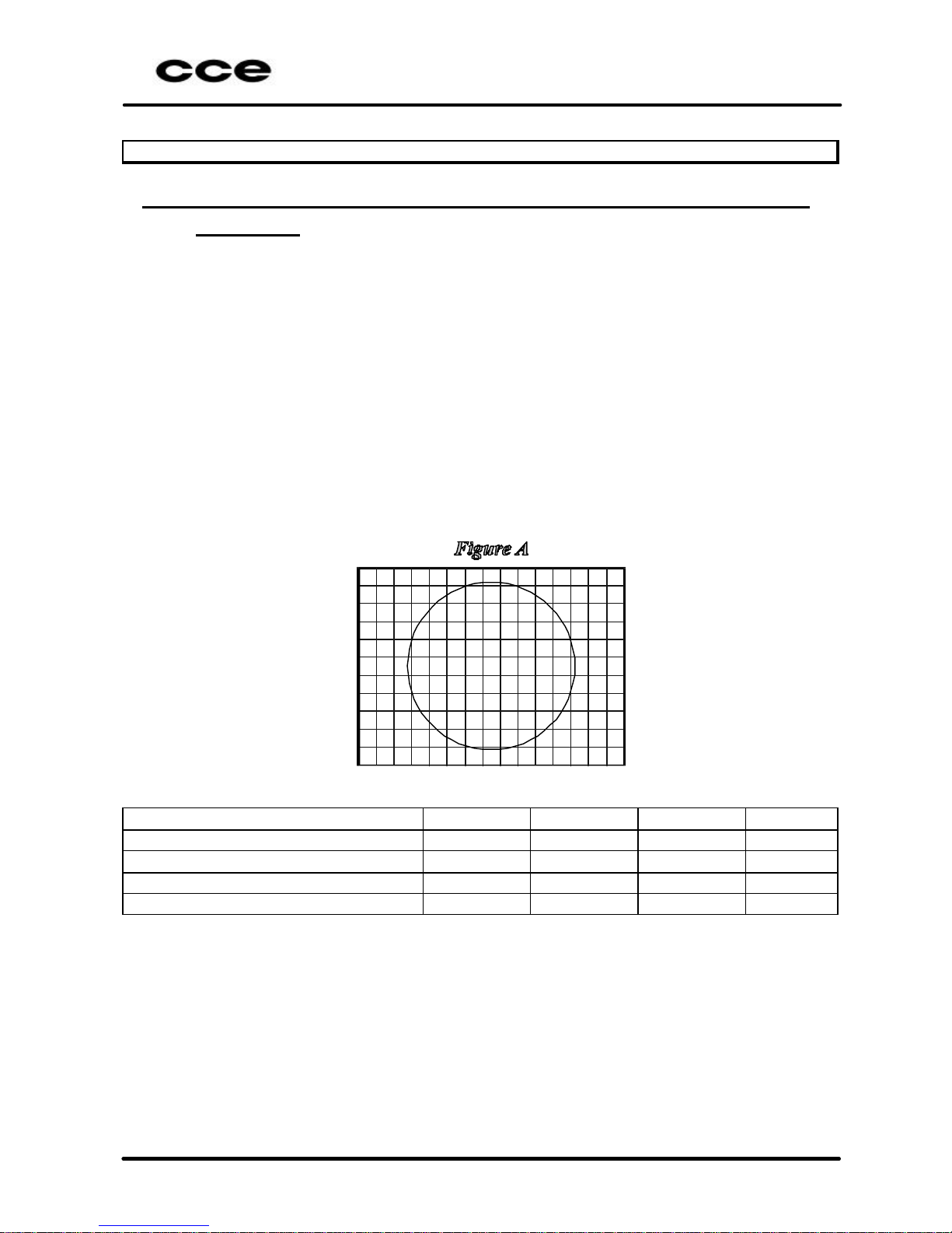
3.3.2 Frame centralization
Preparation:
a) Connect the receiver under test to a 117 VAC line.
Turn On the TV and position the bright and contrast control to the
maximum, and the saturation and volume controls to the minimum position.
Wait for a pre-heating period.
b) Apply a CIRCLE pattern 60dBµV signal with 88% modulation (the preferred
channel will be de fined by the fabric unit).
c) Position to “nominal” the bright and contrast controls.
d) For the next reading, please observe the figure B.
e) Observe the image and make the measures (in centimeters) of the
distances a, b, c and d.
f) Apply the following formula to calculate the horizontal centralization.
(a/b)-(d/c)
g) Observe the image and make the measures (in centimeters) of the
distances p, q, r and s.
h) Apply the formula to calculate the vertical centralization.
(p/q)-(s/r)
Minimum Nominal Maximum Unit
|(a/b)-(d/c)| - 0,00 0,10
|(p/q)-(s/r)| - 0,00 0,20
Page 16
HPS-1478
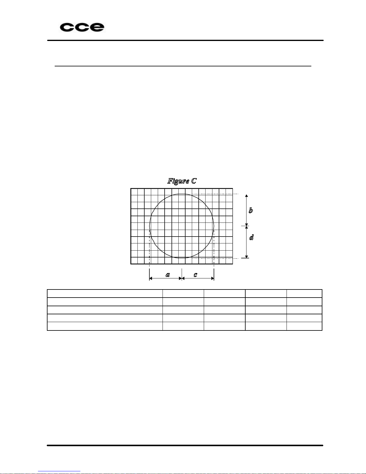
3.3.3 FRAME ASPECT RELATED
a) Connect the receiver under test to a 117VAC line.
Turn on the TV and adjust bright and contrast control to max. position,
saturation and volume to min. Position. Wait for the heat period.
b) Apply to the antenna input a 60dBµV level signal with 88% modulated
PHILIPS pattern (frequency and channel factory defined).
c) Adjust bright and contrast control to nominal position.
d) For the next reads, please utilizes figure C for reference.
e) Observe the screen pattern and check the distances a, b, c, d (in
centimeters).
f) Apply the formula:
M = (a + b + c + d) / 4, and verify the proportion a/M, b/M, c/M e d/M.
Check for systems PAL-M and PAL-N
Minimum Nominal Maximum Unit
a/M 0,95 1,00 1,05
b/M 0,95 1,00 1,05
c/M 0,95 1,00 1,05
d/M 0,95 1,00 1,05
Page 17
HPS-1478
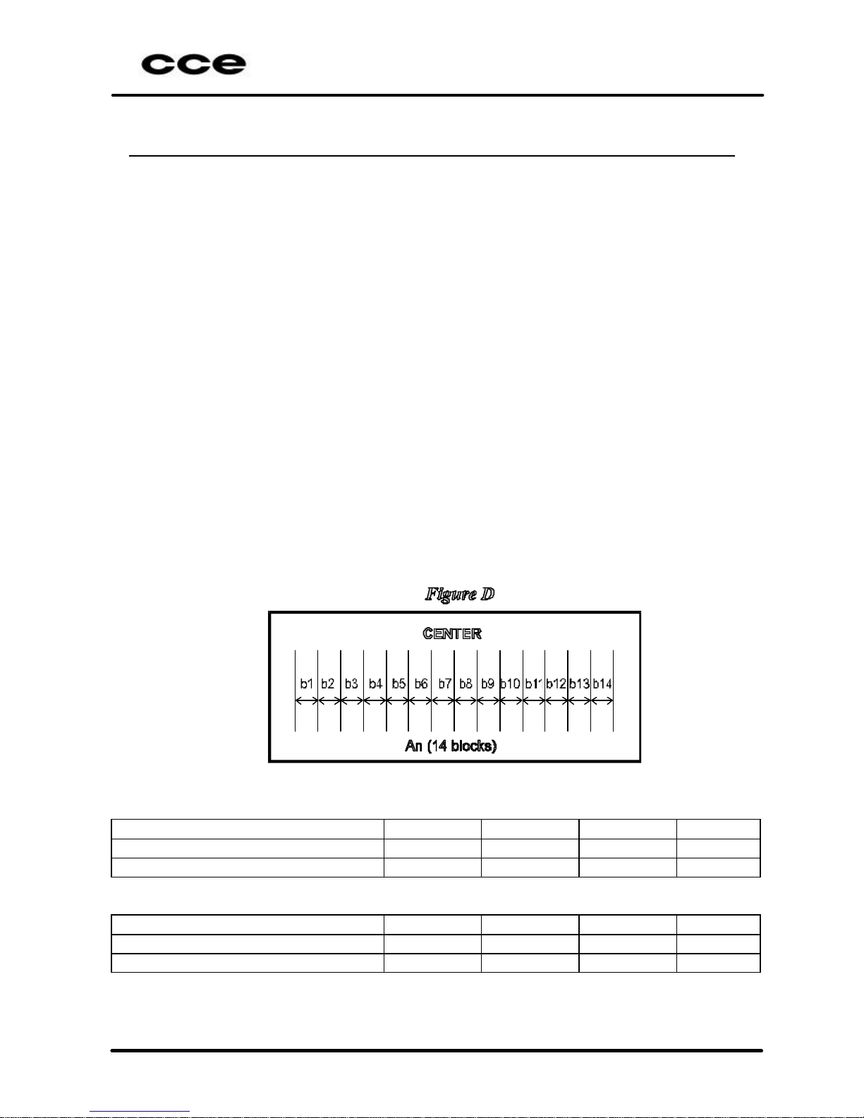
3.3.4 Horizontal Linearity
a) Connect the receiver under test in 117V
AC
line.
Turn on the TV and adjust bright and contrast control to max. position,
saturation and volume to min. Position. Wait for the heat period.
b) Apply to the antenna input a 60dBµV level signal with 88% modulated
PHILIPS pattern (frequency and channel factory defined)
c) Adjust bright and contrast control to nominal position
d) For the next reads, please take references by figure D.
e) Observe the screen pattern and check the distances An - 14 blocks (in
centimeters)
f) Calculate the middle distances through blocks
M = An/14.
Horizontal deviation between major blocks (DHM)
Read first the 14 blocks wide (from b1 to b14) and select the biggest read
(b
max
) for calculate the deviation:
DHM = b
máx
/M
Minor Horizontal deviation between blocks (DHm)
Read first the 14 blocks wide (from b1 to b14) and select the smallest read
(b
min
) for calculate the deviation:
DHm = b
mín
/M
(*)Check for signals PAL-M and PAL-N
PAL-M Minimum Nominal Maximum Unit
DHM - 1,10 1,30
DHm 0,70 0,95 -
PAL-N Minimum Nominal Maximum Unit
DHM - 1,10 1,30
DHm 0,70 0,95 -
Page 18

HPS-1478
3.3.5 Vertical Linearity
a) Connect the receiver to a 117V
AC
line
Turn on the TV and adjust bright and contrast control to max. position,
saturation and volume to min. Position. Wait for the heat period (please see
the specification for this model).
b) Apply to the antenna input a 60dBµV level signal with 88% modulated
PHILIPS pattern (frequency and channel factory defined).
c) Adjust bright and contrast control to nominal position.
d) For the next reads, please take references by figure E.
e) Observe the screen pattern and check the distances X –(in centimeters).
f) Calculate the middle distances through blocks:
a
medium
=X/10.
Major vertical deviation between blocks (DVM).
Read first the 10 blocks height (from a1 to a10) and select the biggest of them
(a
max
) for calculate the deviation :
DVM = a
max/amedium
Minor vertical deviation between blocks (DVm)
Read first the 10 blocks height (from a1 to a10) and select the smallest of
them (a
min
) for calculate the deviation:
DVm = a
min/amedium
(*)Check for signals PAL-M and PAL-N
PAL-M Minimum Nominal Maximum Unit
DVM - 1 1,40
DVm 0,60 1 -
Page 19

HPS-1478
PAL-N Minimum Nominal Maximum Unit
DVM - 1 1,40
DVm 0,60 1 -
3.3.6 Pin-Cushion & Shape of Raster
a) Connect the receiver to a 117V
AC
line.
Turn on the TV and adjust bright and contrast control to max. position,
saturation and volume to min. Position. Wait for the heat period (please see
the specification for this model).
b) Apply to the antenna input a 60dBµV level signal with 88% modulated
“CROSSHATCH” pattern (frequency and channel factory defined).
c) Turn the face tube to West/Lest orientation.
d) Adjust bright and contrast control to “PP” position.
e) For the next reads, please take references by figure F (distances in
millimeters).
f) Observe the screen pattern, to calculate:
Top-Bottom = 2(c1 + c2)/(AD + BC) X 100
Left-Right = 2(d1 + d2)/(AB +CD) X 100
(*) Check for signals PAL-M and PAL-N
Minimum Nominal Maximum Unit
TOP-BOTTOM - - 1,50 %
LEFT-RIGHT - - 2,00 %
Page 20

HPS-1478
3.4 Purity
a) Connect the receiver to a 117V
AC
line
Turn on the TV and adjust bright to nominal position a nd contrast control to
min. position, satura tion and volume to min. position.
b) Apply to the antenna input a 60dBµV level signal with 88% modulated
“WHITE” pattern (frequency and channel factory defined).
c) Wait for pre-heating period (30 minutes).
d) Degauss the device appropriated.
e) Increment the contrast controls to max. position, and wait for 3 minutes
f) At a distance of 5 times the height of the screen, observe that no color dirty
may appear.
g) Repeat this procedures now utilizing a red pattern.
Note:
ü If the receiver is moved during the test procedure, always degauss again the
device
3.5 Convergence
a) Connect the receiver to a 117V
AC
line.
Turn on the TV and adjust bright and contrast control to max.. position,
saturation and volume to min. position. Wait for pre -heating period (please
see specification for each model).
b) Apply to the antenna input a 60dBµV level signal with 88% modulated
“CROSSHATCH” pattern (frequency and channel factory defined).
c) Turn the face tube to Wes t/Lest orientation.
d) Degauss the device properly.
e) Adjust bright and contrast control to minimum position.
Page 21

HPS-1478
M1
M2
M3
f) For the next reads, please take references by figure G (distances in
millimeters).
(mm)
M1
60
M2
120
M3
85
(*) Apply for signals PAL-M and PAL-N.
PONTO X, Y LIMITES (mm)
a
0.4
b, c
0.9
d, e
0.9
f, g, h, j’
1.4
f’, g’, h’, j
1.2
k, l, m, n
1.0
s, t, u, v
0.8
Page 22

HPS-1478
3.6 Video
3.6.1 Sensibility and Signal /Noise Rate
a) Adjust the TV to a “PP” condition.
b) Apply to the antenna input a 60dBµV signal with 60% AM modulation, 1kHz
sine wave (fr equency and channel factory defined).
c) Connect at the output video detector an AC voltmeter and read the voltage
V
AC.
d) Turn off the AM modulation and read the noise level “Vr” (AC voltmeter)
.
e) Calculate the signal-noise rate as following:
S/N=20 log (VAC / VR).
f) Reduce the output level signal generator till the rate S/N reach 20 dB. In
this condition the output level signal generator is the sensibility in dBuV.
Minimum Nominal Maximum Unit
Sensibility - 37,00 46,00 dBµV
S/N 40,00 50,00 - dB
3.6.2 AGC circuit
a) Apply to the antenna input a 60dBµV signal with 88% AM modulation with
“WHITE” pattern (frequency and channel factory defined), and FM sine
wave 400 Hz audio modulation +-25 kHz de viation.
b) Adjust the TV to “PP” condition.
c) Read the DC voltage at the tuner AGC terminal. Utilize a DC electronic
voltmeter with minimum 10 MΩ impedance.
Minimum Nominal Maximum Unit
3,00 4,00 5,00 VDC
3.6.3 AFT circuit
a) Apply to the antenna input a 60dBµV signal with 88% AM modulation with
PAL-M COLOR BAR pattern (frequency and channel factory defined), and
FM sine wave 400 Hz audio modulation +-25 kHz deviation.
b) Connect a oscilloscope in the output video detector and read the peak to
peak burst level signal “Vb”.
c) Increment the generator frequency by 500 kHz and read the new value
peak to peak burst signal “Vh” and calculate the percentage as following:
EH= VH/VB
d) Decrement the generator frequency by 500 kHz and repeat the
procedure(c) reading the peak-to-peak burst signal VL and calculate the
percentage as following:
EL= VL/V
B
Page 23

HPS-1478
Minimum Nominal Maximum Unit
EH 0,85 1 1,15
EL 0,85 1 1,15
3.6.4 Vertical sensitivity
a) Adjust the TV to a “PP” condition.
b) Apply to the antenna input a 60dBµV signal with 88% AM modulation with
PAL-M color pattern (frequency and channel factory defined), and FM sine
wave 1kHz audio modulation +-25 kHz deviation.
c) Observe the TV screen under test and reduce the output generator level
until maintain the stability of the image in the vertical direction and when
there is the instability of the image in the vertical direction, increase the
output generator level until the stability of the image comes back in the
vertical direction. At this condition the output generator level represents the
vertical sensitivity in dBµV.
Note.: If the TV under test is two or three-system mode, repeat this procedures for
the PAL-N and NTSC-M signal system.
Condition Minimum Nominal Maximum Unit
PAL-M - 20,00 23,00 dBµV
PAL-N - 20,00 23,00 dBµV
NTSC-M - 20,00 23,00 dBµV
3.6.5 Chrome sensibility
a) Adjust the TV to a “PP” condition.
b) Apply to the antenna input a 60dBµV signal with 88% AM modulation with
PAL-M color pattern (f requency and channel factory defined), and FM sine
wave 1kHz audio modulation +-25 kHz deviation.
c) Observe the TV screen under test and reduce the output generator level
until the color pattern be visible. At this condition the output generator level
represents the sensibility of chrome in dBµV.
Note.: If the TV under test is two or three-system mode, repeat this procedures for
the PAL-N and NTSC-M signal system.
Condition Minimum Nominal Maximum Unit
PAL-M - 28,00 30,00 dBµV
PAL-N - 28,00 30,00 dBµV
NTSC-M - 28,00 30,00 dBµV
Page 24

HPS-1478
4. CALIBRATION SCRIPT
Note: This guide is only an orientation and, for some items, may be adapted by
Factory Engineering to best conform to the productive process.
4.1 INTRODUCTION
Note:
ü It is necessary to pre-heat the TV during 15 minutes, before its calibration.
1) Important recommendations
2) Definitions of the terms
3) Geometry of the Image
4) White Balance
5) Screen adjustment
6) AGC adjustment
How to select the FACTORY MODE
a) Short to ground pin 78 of IC101 (momentarily) or press the service key in
the service remote control (see the description of service remote control).
b) Select the adjustment options pressing the key CHÙ or CHÚ of the remote
control, of the television front panel or use the service remote control (see
the description of service remote control).
Note: All the adjustment options can be selected directly by the remote control
numeric keys.
c) Adjust the selected option pressing the key VOLØ or ×VOL of the remote
control, of the television front panel or use the service remote control (see
the description of service remote control).
c1) VOLØ - increases registers (MAX.).
c2) ×VOL - decreases registers (MIN.).
d) To exit the FACTORY MODE, use the key OSD/OUT of the remote control.
Page 25

HPS-1478
4.1 Important recommendations
4.1.1 Before beginning the adjustments, the TV set should be a pre-heated during at
least 15 minutes.
4.1.2 The positioning of the TV set should obey the magnetic parameters of South
America that it is -120 vertical mG. In the practice, this is gotten with a relative
precision, positioning the TV set with the face (screen) of the CRT pointing to
the geographical East.
Note: These cares should also be taken when CQ will analyze the TV set.
Page 26

HPS-1478
4.2 Definitions of the registers
Description of service and factory registers
Register Name Range
Description Default Value
01 HSh 00 63 Horizontal shift 45
02 VSD 00 00 Vertical screen 0
03 VSl 00 63 Vertical slope 30
04 VAm 00 63 Vertical amplitude 44
05 VSh 00 63 Vertical shift 32
06 SC 00 63 S-correction 14
The registers bellow must be set to the default values.
Register Name Range
Description Default Value
10 TWBl 00 255 Timing of ‘wide blanking’ 88
11 PWLi 00 63 Peak white limiting 08
12 OSIF 00 63 Off-set IF demodulator 20
13 HzPl 00 63 Horizontal parallelogram 32
14 HBow 00 63 Horizontal bow 32
15 HSh 00 63 Horizontal shift 45
16 EW 00 63 EW width 34
17 PW 00 63 EW parabola/width 35
18 EWUC 00 63 EW upper corner parabol a 35
19 EWLC 00 63 EW lower corner parabola 35
20 TC 00 63 EW trapezium 33
21 VSl 00 63 Vertical slope 30
22 VAm 00 63 Vertical amplitude 44
23 SC 00 63 S-correction 14
24 VSh 00 63 Vertical shift 32
25 VX 00 63 Vertical zoom 25
26 VOT 00 63 Vertical Offset 28
27 TAS 00 63 Text Area Start 13
28 OEA 00 127 Odd Even Alignment 60
29 BLOR 00 63 Black level offset R 32
30 BLOG 00 63 Black level offset G 32
31 WPR 00 63 White point R 32
32 WPG 00 63 White point G 32
33 WPB 00 63 White point B 32
34 PkFr 00 3 Peaking Frequency 1
35 YDl 00 15 Luminance delay time 10
36 AGC 00 63 AGC take-over 25
37 CDc0 00 15 Colour decoder 0 6
38 CDc1 00 7 Colour decoder 1 0
39 AVS0 00 127 AV-switch 0 64
40 AVS1 00 7 AV-switch 1 0
41 Syn0 00 127 Synchronisation 0 0
42 Syn1 00 63 Synchronisation 1 16
Page 27

HPS-1478
43 Defl 00 255 Deflection 16
44 VIF0 00 255 Vision IF 0 32
45 VIF1 00 255 Vision IF 1 2
46 SND0 00 255 Sound 0 10
47 CTL0 00 255 Control 0 0
48 CTL1 00 255 Control 1 0
49 SND1 00 255 Sound 1 0
50 FEA0 00 63 Features 0 0
51 FEA1 00 127 Features 1 0
52 BRI 00 63 Brightness 32
53 CON 00 63 Contrast 63
54 COL 00 63 Color 32
55 PEA 00 63 Peaking 45
The registers bellow must be set to the default values.
Register Name Range
Description Default Value
56 HUE 00 63 Hue 32
57 VOL 00 63 Volume 15
58 STNT 00 15 Stereo noise threshold 8
59 SPNT 00 15 SAP noise threshold 8
60 LA 00 15 Input level adjustment 7
61 ALW 00 31 Alignment for wideband 15
62 ALS 00 31 Alignment for spectral 15
Please, look the functions of registers bellow, before of change to the default
value.
Description of service and factory registers
Register Name Range
Description Default Value
94 STBY 00 2 Standby 1
95 AV-2 00 1 AV2-Conected X
96 ASTU 00 3 Address Select of tuner 0
97 TUNE 00 1 Tuner protocol X
98 INI 00 00 Initialization 0
99 VSD 00 00 Vertical screen 0
Page 28

HPS-1478
Register 94 (STBY) Register 95 (AV-2)
Value Function Value Function
0 The TV set DON’T return
to the STANDBY, after of
the Power On.
0 1 AV input.
1 The TV set, always
return to the STANDBY,
after of the Power On
1 2 AV inputs.
2 Only to the factory. Don’t
use this value.
Register 96 (ASTU) Register 97 (TUNE)
Value Function Value Function
0 When the MAS pin of the
tuner is grounded.
0 To TUNER that run
with Europe protocol.
(Ex. UV1336S/A)
1 When the MAS pin of the
tuner is opened.
1 To TUNER that run
with U.S protocol.
2 When the MAS pin of the
tuner is between 0.4 and
0.6V
3 When the MAS pin of the
tuner is connected to the
+5V.
Register 98 (INI) Register 99 (VSD)
Value Function Value Function
- Initialize all the registers
to the default value.
- To adjust the Screen.
4.3 Geometry of the Image
a) Using the PM - 5515 generator, apply the crosshatch pattern with circle.
b) Adjust the bellow items, until obtaining the best circle symmetry and
positioning, as well as the mi nor image geometric distortion:
ü Use the register ( VSl) to adjust the Vertical slope;
ü Use the register ( VAm) to adjust Vertical Height;
ü Use the register ( VSh) to adjust Vertical position;
ü Use the register ( VSc) to adjust Vertical Center Linearity;
ü Use the register ( HSh) to adjust Horizontal position
Page 29

HPS-1478
4.4 White balance
Note:
ü The cut point doesn’t need adjustment, because it’s automatically made by
the IC101.
ü The white adjustment is already pre-adjusted and incised in the IC101 and,
thus, its adjustment is not necessary.
Otherwise, if it is necessary to change the temperature of the white pattern,
proceed in the following way:
a) Enter in the service mode.
b) Select via CHÙ or CHÚ the WPR (29), WPG (30) and WPB (31) fun ctions.
c) Increase or decrease the function via VOLØ or via ×VOL respectively.
4.5 Screen adjustment
Mode 1:
a) Apply a gray scale pattern.
b) Adjust the controls to:
ü Brightness - 50%
ü Contrast - 70%
c) Measure DC voltage on the three cathodes (CRT) (one at a time) and select
the highest one.
d) Connect a X100 test tip to the selected cathode (highest voltage DC).
e) Adjust the screen potentiometer to obtain 130V, according to the illustration
bellow:
Note. The oscilloscope should be positioned in the vertical mode.
150 Volts
GND
Page 30

HPS-1478
Mode 2:
a) Select the register 99 (VSD).
b) Press VOLØ or ×VOL to select and adjust the screen control localized on
the FBT, until the horizontal line be slightly visible on the screen center.
4.6 AGC adjustment
Mode 1:
ü Apply a PHILIPS pattern with 60dBµV of intensity and adjust the delay
until obtain 3.5V in AGC pin of tuner.
Page 31

HPS-1478
5. MATERIAL LIST
MAIN PCB
CAPACITORS
CODE DESCRIPTION POSITION
1330473400 C.POLYMET 47KPF/250V K C819
1268473566 CAP. POLYMET 47KPF/250V K C819
1330104106 C.POLYEMT 100KPF/63V K C408
1330104018 C.POLYMET 100KPF/50V K C408
1330104106 C.POLYEMT 100KPF/63V K C807
1330104018 C.POLYMET 100KPF/50V K C807
1330104106 C.POLYEMT 100KPF/63V K C812
1330104018 C.POLYMET 100KPF/50V K C812
1330104106 C.POLYEMT 100KPF/63V K C827
1330104018 C.POLYMET 100KPF/50V K C827
1330104421 C.POLYMET 100KPF/250V J C411
1268104556 CAP. POLYMET 100KPF/250V J C411
1330224222 C.POLYMET 220KPF/100V K C303
1330473400 C.POLYMET 47KPF/250V K C424
1268473566 CAP. POLYMET 47KPF/250V K C424
1363101600 C.C.D. Y5E 100PF/500V K C410
1363102601 C.C.D.Y5P 1KPF>=500V K C409
1363102601 C.C.D.Y5P 1KPF>=500V K C420
1363102601 C.C.D.Y5P 1KPF>=500V K C421
1363102601 C.C.D.Y5P 1KPF>=500V K C833
1363472804 C.C.D. Y5U 4,7KPF/2KV M 5SS C802
1363472804 C.C.D. Y5U 4,7KPF/2KV M 5SS C803
1363331803 C.C.D. Y5P 330PF/2KV K 6LS C828
1492047100 CAP.SMD X7R 470PF/50V K 0603 C407
1494047104 CAP.SMD CH 470PF/50V J 0805 C407
1363471301 CCD Y5P 470PF/100V K C902
1363471301 CCD Y5P 470PF/100V K C904
1363471301 CCD Y5P 470PF/100V K C906
1492047100 CAP.SMD X7R 470PF/50V K 0603 C839
1494047104 CAP.SMD CH 470PF/50V J 0805 C839
1363472804 C.C.D. Y5U 4,7KPF/2KV M 5SS C804
1364104102 C.C.D.Y5V 100KPF>=25V Z C806
1364222795 CCD.SWIT.MOD.Y5P 2,2KPF/1KV K C430
1380100524 ELCO 10UF/50V M 5X11MM C104
1380100524 ELCO 10UF/50V M 5X11MM C201
1380100524 ELCO 10UF/50V M 5X11MM C603
1380100524 ELCO 10UF/50V M 5X11MM C718
1380100524 ELCO 10UF/50V M 5X11MM C901
1380101224 ELCO 100UF/16V M 5X11MM C705
1380101228 ELCO 100UF/16V M 6,3x11MM C705
1380101924 ELCO 100UF/10V M 5X11MM C705
1380101224 ELCO 100UF/16V M 5X11MM C706
1380101228 ELCO 100UF/16V M 6,3x11MM C706
1380101924 ELCO 100UF/10V M 5X11MM C706
1380101224 ELCO 100UF/16V M 5X11MM C720
Page 32

HPS-1478
CODE DESCRIPTION POSITION
1380101228 ELCO 100UF/16V M 6,3x11MM C720
1380101228 ELCO 100UF/16V M 6,3x11MM C720
1380101224 ELCO 100UF/16V M 5X11MM C720
1380101224 ELCO 100UF/16V M 5X11MM C742
1380101228 ELCO 100UF/16V M 6,3x11MM C742
1380101228 ELCO 100UF/16V M 6,3x11MM C742
1380101224 ELCO 100UF/16V M 5X11MM C742
1380101224 ELCO 100UF/16V M 5X11MM C634
1380101228 ELCO 100UF/16V M 6,3x11MM C634
1380101228 ELCO 100UF/16V M 6,3x11MM C634
1380101224 ELCO 100UF/16V M 5X11MM C634
1380101328 ELCO 100UF/25V M 6,3X11MM C834
1380101328 ELCO 100UF/25V M 6,3X11MM C836
1380101328 ELCO 100UF/25V M 6,3X11MM C851
1380101630 ELCO 100UF/35V M 6,3X11MM C302
1380109622 ELCO 1UF/100V M 5x11mm C401
1380109828 ELCO 1UF/250V M 6,3X11MM C401
1380109720 ELCO 1UF/63V M 5X11MM C401
1380109524 ELCO 1UF/50V M 5X11MM C401
1380109622 ELCO 1UF/100V M 5x11mm C404
1380109828 ELCO 1UF/250V M 6,3X11MM C404
1380109720 ELCO 1UF/63V M 5X11MM C404
1380109524 ELCO 1UF/50V M 5X11MM C404
1380109622 ELCO 1UF/100V M 5x11mm C419
1380109828 ELCO 1UF/250V M 6,3X11MM C419
1380109720 ELCO 1UF/63V M 5X11MM C419
1380109524 ELCO 1UF/50V M 5X11MM C419
1380109622 ELCO 1UF/100V M 5x11mm C647
1380109828 ELCO 1UF/250V M 6,3X11MM C647
1380109720 ELCO 1UF/63V M 5X11MM C647
1380109524 ELCO 1UF/50V M 5X11MM C647
1380109622 ELCO 1UF/100V M 5x11mm C722
1380109828 ELCO 1UF/250V M 6,3X11MM C722
1380109720 ELCO 1UF/63V M 5X11MM C722
1380109524 ELCO 1UF/50V M 5X11MM C722
1380109622 ELCO 1UF/100V M 5x11mm C824
1380109828 ELCO 1UF/250V M 6,3X11MM C824
1380109720 ELCO 1UF/63V M 5X11MM C824
1380109524 ELCO 1UF/50V M 5X11MM C824
1380220528 ELCO 22UF/50V M 5X11MM C101
1380220528 ELCO 22UF/50V M 5X11MM C808
1363471600 C.C.D.Y5P/Y5E 470PF>=500V K C809
1380221231 ELCO 220UF/16V M 6,3X11MM C838
1380229622 ELCO 2,2UF/100V M 5X11MM C204
1380229622 ELCO 2,2UF/100V M 5X11MM C606
1380330921 ELCO 33UF/160V M 10X20MM C829
1290330921 E LCO 33UF/160V M 10X20MM C829
1380470324 ELCO 47UF/25V M 5X11MM C703
1380470324 ELCO 47UF/25V M 5X11MM C835
1380470324 ELCO 47UF/25V M 5X11MM C850
Page 33

HPS-1478
CODE DESCRIPTION POSITION
1380471225 ELCO 470UF/16V M 8X11,5MM C107
1380471229 ELCO 470UF/16V M 10X12,5MM C107
1380471225 ELCO 470UF/16V M 8X11,5MM C425
1380471229 ELCO 470UF/16V M 10X12,5MM C425
1380471225 ELCO 470UF/16V M 8X11,5MM C426
1380471229 ELCO 470UF/16V M 10X12,5MM C426
1380471225 ELCO 470UF/16V M 8X11,5MM C635
1380471229 ELCO 470UF/16V M 10X12,5MM C635
1380479032 ELCO 4,7UF/250V M 10X12,5MM C423
1380479622 ELCO 4,7UF/100V M 5x11mm C207
1380479522 ELCO 4,7UF/50V M 5X11MM C207
1380479522 ELCO 4,7UF/50V M 5X11MM C207
1380479622 ELCO 4,7UF/100V M 5x11mm C207
1380479622 ELCO 4,7UF/100V M 5x1 1mm C406
1380479522 ELCO 4,7UF/50V M 5X11MM C406
1380479522 ELCO 4,7UF/50V M 5X11MM C406
1380479622 ELCO 4,7UF/100V M 5x11mm C406
1380479732 ELCO 4,7UF/160V M 6,3X11MM C415
1492010400 CAP.SMD X7R 100KPF/16V K 0603 C637
1490510400 CAP.SMD X7R 100KPF/50V K 0805 C637
1490522420 CAP.SMD X7R 220KPF/16V K 0805 C632
1380100524 ELCO 10UF/50V M 5X11MM C638
1490522420 CAP.SMD X7R 220KPF/16V K 0805 C730
1491010104 CAP.SMD NP0 100PF/50V J 0603 C210
1490410104 CAP.SMD NPO 100PF/50V J 0805 C210
1491010103 CAP. SMD NP0 100PF/100V J 0603 C210
1491082004 CAP.SMD NP0 82PF/50V J 0603 C210
1491010104 CAP.SMD NP0 100PF/50V J 0603 C652
1490410104 CAP.SMD NPO 100PF/50V J 0805 C652
1491010103 CAP. SMD NP0 100PF/100V J 0603 C652
1491082004 CAP.SMD NP0 82PF/50V J 0603 C652
1491010104 CAP.SMD NP0 100PF/50V J 0603 C715
1490410104 CAP.SMD NPO 100PF/50V J 0805 C715
1491010103 CAP. SMD NP0 100PF/100V J 0603 C715
1491082004 CAP.SMD NP0 82PF/50V J 0603 C715
1491010104 CAP.SMD NP0 100PF/50V J 0603 C716
1490410104 CAP.SMD NPO 100PF/50V J 0805 C716
1491010103 CAP. SMD NP0 100PF/100V J 0603 C716
1491082004 CAP.SMD NP0 82PF/50V J 0603 C716
1491010104 CAP.SMD NP0 100PF/50V J 0603 C717
1490410104 CAP.SMD NPO 100PF/50V J 0805 C717
1491010103 CAP. SMD NP0 100PF/100V J 0603 C717
1491082004 CAP.SMD NP0 82PF/50V J 0603 C717
1491033004 CAP.SMD NP0 33PF/50V J 0603 C701
1491033004 CAP.SMD NP0 33PF/50V J 0603 C702
1491033004 CAP.SMD NP0 33PF/50V J 0603 C709
1491033004 CAP.SMD NP0 33PF/50V J 0603 C710
1360330300 C.C.D.NPO 33PF/50V K C711
1360330300 C.C.D.NPO 33PF/50V K C712
1491039104 CAP.SMD NP0 390PF/50V J 0603 C903
Page 34

HPS-1478
CODE DESCRIPTION POSITION
1492039101 CAP.SMD X7R 390PF/50V K 0603 C903
1491039104 CAP.SMD NP0 390PF/50V J 0603 C905
1492039101 CAP.SMD X7R 390PF/50V K 0603 C905
1491039104 CAP.SMD NP0 390PF/50V J 0603 C907
1492039101 CAP.SMD X7R 390PF/50V K 0603 C907
1492010200 CAP.SMD X7R 1KPF/50V K 0603 C305
1492010200 CAP.SMD X7R 1KPF/50V K 0603 C306
1492010200 CAP.SMD X7R 1KPF/50V K 0603 C648
1492010200 CAP.SMD X7R 1KPF/50V K 0603 C714
1492010200 CAP.SMD X7R 1KPF/50V K 0603 C771
1492010300 CAP.SMD X7R 10KPF/50V K 0603 C105
1492010300 CAP.SMD X7R 10KPF/50V K 0603 C106
1492010300 CAP.SMD X7R 10KPF/50V K 0603 C206
1492010300 CAP.SMD X7R 10KPF/50V K 0603 C304
1492010300 CAP.SMD X7R 10KPF/50V K 0603 C402
1492010300 CAP.SMD X7R 10KPF/50V K 0603 C837
1492010400 CAP.SMD X7R 100KPF/16V K 0603 C102
1490510400 CAP.SMD X7R 100KPF/50V K 0805 C102
1492010400 CAP.SMD X7R 100KPF/16V K 0603 C203
1490510400 CAP.SMD X7R 100KP F/50V K 0805 C203
1492010400 CAP.SMD X7R 100KPF/16V K 0603 C211
1490510400 CAP.SMD X7R 100KPF/50V K 0805 C211
1492010400 CAP.SMD X7R 100KPF/16V K 0603 C740
1490510400 CAP.SMD X7R 100KPF/50V K 0805 C740
1492012200 CAP.SMD X7R 1,2KPF/50V K 0603 C601
1490512200 CAP. SMD X7R 1,2KPF/50V K 0805 C601
1494212200 CAP.SMD Y5P 1,2KPF/50V K 0805 C601
1492022200 CAP.SMD X7R 2,2KPF/50V K 0603 C405
1490522200 CAP.SMD X7R 2,2KPF/50V K 0805 C405
1494222200 CAP.SMD Y5P 2,2KPF/50V K 0805 C405
1492022300 CAP.SMD X7R 22KPF/25V K 0603 C205
1492022300 CAP.SMD X7R 22KPF/25V K 0603 C560
1492022300 CAP.SMD X7R 22KPF/25V K 0603 C561
1492022300 CAP.SMD X7R 22KPF/25V K 0603 C562
1492022300 CAP.SMD X7R 22KPF/25V K 0603 C604
1492022300 CAP.SMD X7R 22KPF/25V K 0603 C704
1492022300 CAP.SMD X7R 22KPF/25V K 0603 C707
1492022300 CAP.SMD X7R 22KPF/25V K 0603 C719
1492033100 CAP.SMD X7R 330PF/50V K 0603 C602
1494039104 CAP.SMD CH 390PF/50V J 0805 C602
1492047100 CAP.SMD X7R 470PF/50V K 0603 C502
1494047104 CAP.SMD CH 470PF/50V J 0805 C502
1492047200 CAP.SMD X7R 4,7KPF/50V K 0603 C403
1492047200 CAP.SMD X7R 4,7KPF/50V K 0603 C605
1493022405 CAP.SMD Y5V 220KPF/16V Z 0603 C501
1493022405 CAP.SMD Y5V 220KPF/16V Z 0603 C721
1492047300 CAP.SMD X7R 47KPF/16V K 0603 C213
1491010104 CAP.SMD NP0 100PF/50V J 0603 C214
1490410104 CAP.SMD NPO 100PF/50V J 0805 C214
1491010103 CAP. SMD NP0 100PF/100V J 0603 C214
Page 35

HPS-1478
CODE DESCRIPTION POSITION
1491082004 CAP.SMD NP0 82PF/50V J 0603 C214
1265104074 C.POLYPRO 100KPF/250VAC K X3 C801
1265104576 C.POLY.M.100KPF/250VAC M SUPX2 C801
1265414552 CAP.POLYPRO 410KPF/250V J C416
1265414556 CAP. POLYPRO 410KPF/250V J C416
1265272952 CAP.PP MFP RM15 2K7PF/1K6V J C815
1265272956 CAP. POLYPRO 2K7PF/1K6V J C815
1265912955 CAP.POLYPRO MKP 9,1KPF/2KV J C418
1265912953 CAP.POLYPRO MFP 9,1KPF/2KV J C418
1265912952 CAP.POLYPRO MET.9,1KPF/1600V J C418
1265912639 CAP.POLYPRO 9,1NF/1,6KV J C418
1265912956 CAPACITOR POLYPRO 9,1NF/2KV J C418
1291220017 ELCO 22UF/250V M 10X20MM C908
1292151054 ELCO 150UF/385V M 22X40MM C805
1291102318 ELCO 1000UF/16V M 10X16MM C636
1291102317 ELCO 1000UF/16V M 10X16MM C636
1291102318 ELCO 1000UF/16V M 10X16MM C831
1291102317 ELCO 1000UF/16V M 10X16MM C831
1331104004 CAP.POLYPRO 100KPF/160V 5% C301
1265104556 CAP. POLYPRO 100KPF/250V J C301
1363102802 C.C.D. Y5F 1KPF/2KV M C909
1363331803 C.C.D. Y5P 330PF/2KV K 6LS C417
1247222453 C.C.D. GZO 2,2NF/250VAC 61V C823
1369222804 C.C.D. GKO 2K2PF/250VAC M C823
1380470921 ELCO 47UF/160V M 12,5X25MM HR C825
1290470921 ELCO 47UF/160V M 12,5x25MM HR C825
RESISTORS
CODE DESCRIPTION POSITION
1183510092 RES.METAL FILME 1/2W 10R 5% N R826
1183510192 RES.METAL FILME 1/2W 100R 5% N R103
1182510193 RES.CARBONO 1/4W 100R 5% N R103
1183510192 RES.METAL FILME 1/2W 100R 5% N R104
1182510193 RES.CARBONO 1/4W 100R 5% N R104
1183510192 RES.METAL FILME 1/2W 100R 5% N R302
1182510193 RES.CARBONO 1/4W 100R 5% N R302
1183510192 RES.METAL FILME 1/2W 100R 5% N R303
1182510193 RES.CARBONO 1/4W 100R 5% N R303
1183510192 RES.METAL FILME 1/2W 100R 5% N R508
1183510192 RES.METAL FILME 1/2W 100R 5% N R509
1183510192 RES.METAL FILME 1/2W 100R 5% N R510
1502510103 RES.SMD 100R 5% 0603 R567
1502510102 RES.SMD 100R 5% 0805 R567
1183510192 RES.METAL FILME 1/2W 100R 5% N R701
1182510193 RES.CARBONO 1/4W 100R 5% N R701
1183510192 RES.METAL FILME 1/2W 100R 5% N R702
1182510193 RES.CARBONO 1/4W 100R 5% N R702
1183510192 RES.METAL FILME 1/2W 100R 5% N R709
1182510193 RES.CARBONO 1/4W 100R 5% N R709
1183510192 RES.METAL FILME 1/2W 100R 5% N R712
Page 36

HPS-1478
CODE DESCRIPTION POSITION
1182510193 RES.CARBONO 1/4W 100R 5% N R712
1183510192 RES.METAL FILME 1/2W 100R 5% N R713
1182510193 RES.CARBONO 1/4W 100R 5% N R713
1183510192 RES.METAL FILME 1/2W 100R 5% N R719
1182510193 RES.CARBONO 1/4W 100R 5% N R719
1502510203 RES.SMD 1K 5% 0603 R201
1502500003 RES.SMD 0R 5% 0603 R217
1502500002 RES.SMD 0R 5% 0805 R217
1183510292 RES.METAL FILME 1/2W 1K 5% N R507
1183510292 RES.METAL FILME 1/2W 1K 5% N R809
1183547292 RES.METAL FILME 1/2W 4,7K 5% N R811
1183510292 RES.METAL FILME 1/2W 1K 5% N R901
1183510292 RES.METAL FILME 1/2W 1K 5% N R909
1183510292 RES.METAL FILME 1/2W 1K 5% N R918
1183510292 RES.METAL FILME 1/2W 1K 5% N R927
1502510403 RES.SMD 100K 5% 0603 R421
1183510992 RES.METAL FILME 1/2W 1R 5% N R813
1183512292 RES.METAL FILME 1/2W 1,2K 5% N R112
1502512203 RES.SMD 1,2K 5% 0603 R721
1183512392 RES.METAL FILME 1/2W 12K 5% N R106
1183512392 RES.METAL FILME 1/2W 12K 5% N R107
1183512392 RES.METAL FILME 1/2W 12K 5% N R108
1183512392 RES.METAL FILME 1/2W 12K 5% N R109
1183515292 RES.METAL FILME 1/2W 1,5K 5% N R304
1183515292 RES.METAL FILME 1/2W 1,5K 5% N R305
1183515292 RES.METAL FILME 1/2W 1,5K 5% N R831
1183522492 RES.METAL FILME 1/2W 220K 5% N R804
1183515492 RES.METAL FILME 1/2W 150K 5% N R806
1183515992 RES.METAL FILME 1/2W 1,5R 5% N R306
1183518392 RES.METAL FILME 1/2W 18K 5% N R414
1183518492 RES.METAL FILME 1/2W 180K 5% N R931
1183518492 RES.METAL FILME 1/2W 180K 5% N R932
1183522092 RES.METAL FILME 1/2W 22R 5% N R416
1183510292 RES.METAL FILME 1/2W 1K 5% N R834
1502522303 RES.SMD 22K 5% 0603 R614
1502510303 RES.SMD 10K 5% 0603 R615
1502522203 RES.SMD 2,2K 5% 0603 R651
1183527192 RES.METAL FILME 1/2W 270R 5% N R807
1183527392 RES.METAL FILME 1/2W 27K 5% N R404
1183527492 RES.METAL FILME 1/2W 270K 5% N R803
1183533092 RES.METAL FILME 1/2W 33R 5% N R902
1183533092 RES.METAL FILME 1/2W 33R 5% N R911
1183533192 RES.METAL.FILME 1/2W 330R 5% N R307
1183533992 RES.METAL FILME 1/2W 3,3R 5% N R308
1183533992 RES.METAL FILME 1/2W 3,3R 5% N R309
1183533992 RES.METAL FILME 1/2W 3,3R 5% N R824
1183539392 RES.METAL FILME 1/2W 39K 5% N R415
1183547292 RES.METAL FILME 1/2W 4,7K 5% N R215
1183547292 RES.METAL FILME 1/2W 4,7K 5% N R722
1183547392 RES.METAL.FILME 1/2W 47K 5% N R208
Page 37

HPS-1478
CODE DESCRIPTION POSITION
1183547392 RES.METAL.FILME 1/2W 47K 5% N R209
1183556192 RES.METAL FILME 1/2W 560R 5% N R823
1183556392 RES.METAL FILME 1/2W 56K 5% N R810
1183568192 RES.METAL FILME 1/2W 680R 5% N R102
1183568992 RES.METAL FILME 1/2W 6,8R 5% N R822
1183582192 RES.METAL FILME 1/2W 820R 5% N R820
1183582292 RES.METAL FILME 1/2W 8,2K 5% N R410
1189111331 RES.PRECISAO 0,6W 113K 0,5% R816
1189511395 RES.PRECISAO 1/2WS 113K 0,5% R816
1189511395 RES.PRECISAO 1/2WS 113K 0,5% R816
1189111331 RES.PRECISAO 0,6W 113K 0,5% R816
1189128231 RES.PRECISAO 0,6W 2,8K 0,5% R817
1189528295 RES.PRECISAO 1/2WS 2,8K 0,5% R817
1189528295 RES.PRECISAO 1/2WS 2,8K 0,5% R817
1189128231 RES.PRECISAO 0,6W 2,8K 0,5% R817
1189139331 RES.PRECISAO 0,4W 39K 1% N R301
1189539395 RES.PRECISAO 1/2WS 39K 0,5% R301
1189539395 RES.PRECISAO 1/2WS 39K 0,5% R301
1189139331 RES.PRECISAO 0,4W 39K 1% N R301
1502547203 RES.SMD 4,7K 5% 0603 RU746
1502547202 RES.SMD 4,7K 5% 0805 RU746
1502568203 RES.SMD 6,8K 5% 0603 R610
1183510292 RES.METAL FILME 1/2W 1K 5% N R407
1502510203 RES.SMD 1K 5% 0603 R705
1502510303 RES.SMD 10K 5% 0603 R413
1502510303 RES.SMD 10K 5% 0603 R420
1502510303 RES.SMD 10K 5% 0603 R836
1502510303 RES.SMD 10K 5% 0603 R848
1502510403 RES.SMD 100K 5% 0603 R605
1502533103 RES.SMD 330R 5% 0603 R203
1502515103 RES.SMD 150R 5% 0603 R409
1183515192 RES.METAL FILME 1/2W 150R 5% N R426
1502518103 RES.SMD 180R 5% (0603) R776
1502518203 RES.SMD 1,8K 5% 0603 R908
1502518203 RES.SMD 1,8K 5% 0603 R917
1502518203 RES.SMD 1,8K 5% 0603 R926
1502522003 RES.SMD 22R 5% 0603 R906
1502522003 RES.SMD 22R 5% 0603 R915
1502522003 RES.SMD 22R 5% 0603 R924
1502522103 RES.SMD 220R 5% 0603 R777
1502522203 RES.SMD 2,2K 5% 0603 R749
1502522203 RES.SMD 2,2K 5% 0603 R837
1502522303 RES.SMD 22K 5% 0603 R402
1502522303 RES.SMD 22K 5% 0603 R403
1502522303 RES.SMD 22K 5% 0603 R412
1502522303 RES.SMD 22K 5% 0603 R417
1183522392 RES.METAL FILME 1/2W 22K 5% N R833
1502522303 RES.SMD 22K 5% 0603 R845
1502539103 RES.SMD 390R 5% 0603 R204
1502539102 RES.SMD 390R 5% 0805 R204
Page 38

HPS-1478
CODE DESCRIPTION POSITION
1502547103 RESISTOR SMD 470R 5% 0603 R205
1502527303 RES.SMD 27K 5% 0603 R418
1502527302 RES.SMD 27K 5% 0805 R418
1502527303 RES.SMD 27K 5% 0603 R422
1502527302 RE S.SMD 27K 5% 0805 R422
1502533003 RES.SMD 33R 5% 0603 R920
1502533103 RES.SMD 330R 5% 0603 R778
1502533103 RES.SMD 330R 5% 0603 R907
1502533103 RES.SMD 330R 5% 0603 R916
1502533103 RES.SMD 330R 5% 0603 R925
1502539103 RES.SMD 390R 5% 0603 R105
1502539102 RES.SMD 390R 5% 0805 R105
1502539103 RES.SMD 390R 5% 0603 R408
1502539102 RES.SMD 390R 5% 0805 R408
1502539203 RES.SMD 3,9K 5% 0603 R405
1502539202 RES.SMD 3,9K 0805 R405
1502539203 RES.SMD 3,9K 5% 0603 R601
1502539202 RES.SMD 3,9K 0805 R601
1502539203 RES.SMD 3,9K 5% 0603 R101
1502539202 RES.SMD 3,9K 0805 R101
1502547003 RES.SMD 47R 5% 0603 R706
1502547103 RESISTOR SMD 470R 5% 0603 R779
1502510203 RES.SMD 1K 5% 0603 R844
1502547203 RES.SMD 4,7K 5% 0603 R704
1502547203 RES.SMD 4,7K 5% 0603 R714
1502547202 RES.SMD 4,7K 5% 0805 R714
1502547203 RES.SMD 4,7K 5% 0603 R723
1502547202 RES.SMD 4,7K 5% 0805 R723
1183547192 RES.METAL FILME 1/2W 470R 5% N R742
1502515303 RES.SMD 15K 5% 0603 R818
1502515302 RES.SMD 15K 5% 0805 R818
1502547203 RES.SMD 4,7K 5% 0603 R842
1502547202 RES.SMD 4,7K 5% 0805 R842
1502547303 RES.SMD 47K 5% 0603 R843
1502547403 RES.SMD 470K 5% 0603 R419
1502547402 RES.SMD 470K 5% (0805) R419
1502547903 RES.SMD 4,7R 5% 0603 R202
1502547203 RES.SMD 4,7K 5% 0603 R703
1502556203 RES.SMD 5,6K 5% 0603 R847
1502556202 RES.SMD 5,6K 5% N 0805 R847
1502582103 RES.SMD 820R 5% 0603 R406
1502582103 RES.SMD 820R 5% 0603 R780
1183547292 RES.METAL FILME 1/2W 4,7K 5% N RG744
1183547292 RES.METAL FILME 1/2W 4,7K 5% N RG745
1502582103 RES.SMD 820R 5% 0603 R840
1502500003 RES.SMD 0R 5% 0603 R612
1502500002 RES.SMD 0R 5% 0805 R612
1502575003 RES.SMD 75R 5% 0603 R216
1183547192 RES.METAL FILME 1/2W 470R 5% N R219
1183510192 RES.METAL FILME 1/2W 100R 5% N R220
Page 39

HPS-1478
CODE DESCRIPTION POSITION
1183510192 RES.METAL FILME 1/2W 100R 5% N R832
1125707400 RES.COEF.NEG.NTC 10R NTC801
1184515325 RES.M.FILME 2W 15K 5% D.KINK R904
1184515325 RES.M.FILME 2W 15K 5% D.KINK R913
1184515325 RES.M.FILME 2W 15K 5% D.KINK R922
1185510929 FUSISTOR 1W 1R 5% RADIAL TAPED FR401
1185510926 FUSISTOR 1W 1R 5% D.KINK FR401
1185522026 FUSISTOR 1W 22R 5% D.KINK FR901
1185522825 RES.M.FILME 1W 022R 5% D.KINK R812
1185522851 RES. M. FILME 1W 0,22R 5% RAD R812
1185522812 RES.METAL FILME 1W 0,22R 5% N R812
1183510028 FUSISTOR 1/2W 10R 5% R.TAPED FR801
1183510026 FUSISTOR 1/2W 10R 5% D.KINK FR801
1185547027 RES.M.FILME 1W 47R 5% R.TAPED R113
1185547025 RES.M.FILME 1W 47R 5% D.KINK R113
1185547027 RES.M.FILME 1W 47R 5% R.TAPED R830
1185547025 RES.M.FILME 1W 47R 5% D.KINK R830
1185547125 RES.M.FILME 1W 470R 5% D.KINK R207
1187556225 RES.M.FILME 3W 5,6K 5% D.KINK R411
1183510128 FUSISTOR 1/2W 100R 5% R.TAPED FR802
1183510126 FUSISTOR 1/2W 100R 5% D.KINK FR802
1183510928 FUSISTOR 1/2W 1R 5% R.TAPED FR402
1183510926 FUSISTOR 1/2W 1R 5% D.KINK FR402
1183510928 FUSISTOR 1/2W 1R 5% R.TAPED FR403
1183510926 FUSISTOR 1/2W 1R 5% D.KINK FR403
1183510928 FUSISTOR 1/2W 1R 5% R.TAPED FR404
1183510926 FUSISTOR 1/2W 1R 5% D.KINK FR404
1183510928 FUSISTOR 1/2W 1R 5% R.TAPED FR405
1183510926 FUSISTOR 1/2W 1R 5% D.KINK FR405
1183522228 FUSISTOR 1/2W 2,2K 5% R.TAPED FR804
1183522226 FUSISTOR 1/2W 2K2 5% D.KINK FR804
1183615249 RESISTOR ALTA TENSAO 1/2W 1K5 K R910
1183615219 RES.COMPOS.1/2W 1,5K 5% N R910
1183615249 RESISTOR ALTA TENSAO 1/2W 1K5 K R919
1183615219 RES.COMPOS.1/2W 1,5K 5% N R919
1183615249 RESISTOR ALTA TENSAO 1/2W 1K5 K R928
1183615219 RES.COMPOS.1/2W 1,5K 5% N R928
1183568549 RESISTOR ALTA TENSAO 1/2W 6M8 J R815
1183668519 RES. COMPOSIÇAO 1/2W 6,8M K R815
SEMICONDUCTORS
CODE DESCRIPTION POSITION
1320091000 TRANSISTOR BC337/25 Q101
1320091000 TRANSISTOR BC337/25 Q802
1320091000 TRANSISTOR BC337/25 Q804
1320090500 TRANSISTOR BF422 Q901
1320091400 TRANSISTOR 2SC-3333 Q901
1320090500 TRANSISTOR BF422 Q903
1320091400 TRANSISTOR 2SC-3333 Q903
1320090500 TRANSISTOR BF422 Q905
Page 40

HPS-1478
CODE DESCRIPTION POSITION
1320091400 TRANSISTOR 2SC-3333 Q905
1320090800 TRANSISTOR KSP42TA/MPSA42RL1 Q401
1320091100 TRANSISTOR BF421 Q902
1320091300 TRANSISTOR 2SA-1320 Q902
1320091100 TRANSISTOR BF421 Q904
1320091300 TRANSISTOR 2SA-1320 Q904
1320091100 TRANSISTOR BF421 Q906
1320091300 TRANSISTOR 2SA-1320 Q906
1700100011 TRANSISTOR SMD BC856B Q403
1700100011 TRANSISTOR SMD BC856B Q806
1700100015 TRANSISTOR SMD BC846B Q201
1700100003 TRANSISTOR SMD BC847B Q201
1700100015 TRANSISTOR SMD BC846B Q404
1700100003 TRANSISTOR SMD BC847B Q404
1700100015 TRANSISTOR SMD BC846B Q601
1700100003 TRANSISTOR SMD BC847B Q601
1700100015 TRANSISTOR SMD BC846B Q808
1700100003 TRANSISTOR SMD BC847B Q808
1700100015 TRANSISTOR SMD BC846B Q807
1700100003 TRANSISTOR SMD BC847B Q807
1139999468 TRANS.POWER MOSFET STP6NK90ZFP Q801
1139999469 TRANSISTOR 2SK3565 Q801
1139999470 TRANSISTOR BU1506DX SOT-186 A Q402
1415180901 DIODO RETIFICADOR SK107 D301
1415180902 DIODO RETIFICADOR RL107FIT D301
1410450110 DIODO RETIFICADOR SK-1/08 D809
1410450110 DIODO RETIFICADOR SK-1/08 D810
1410450110 DIODO RETIFICADOR SK-1/08 D811
1410450110 DIODO RETIFICADOR SK-1/08 D812
1414621902 DIODO 1N4148T50R/1N4148T50A(_Q D101
1414621902 DIODO 1N4148T50R/1N4148T50A(_Q D201
1414621902 DIODO 1N4148T50R/1N4148T50A(_Q D405
1414621902 DIODO 1N4148T50R/1N4148T50A(_Q D406
1414621902 DIODO 1N4148T50R/1N4148T50A(_Q D407
1414621902 DIODO 1N4148T50R/1N4148T50A(_Q D408
1414621902 DIODO 1N4148T50R/1N4148T50A(_Q D710
1414621902 DIODO 1N4148T50R/1N4148T50A(_Q D711
1414621902 DIODO 1N4148T50R/1N4148T50A(_Q D813
1414621902 DIODO 1N4148T50R/1N4148T50A(_Q D814
1414621902 DIODO 1N4148T50R/1N4148T50A(_Q D819
1414621902 DIODO 1N4148T50R/1N4148T50A(_Q D820
1414621902 DIODO 1N4148T50R/1N4148T50A(_Q D823
1414621902 DIODO 1N4148T50R/1N4148T50A(_Q D901
1414621902 DIODO 1N4148T50R/1N4148T50A(_Q D902
1414621902 DIODO 1N4148T50R/1N4148T50A(_Q D903
1414621902 DIODO 1N4148T50R/1N4148T50A(_Q D904
1414621903 DIODO BAV21 D302
1414621905 DIODO DE CHAVEAMENTO 1SS244T77 D302
1414621905 DIODO DE CHAVEAMENTO 1SS244T77 D302
1414621903 DIODO BAV21 D302
Page 41

HPS-1478
CODE DESCRIPTION POSITION
1414621903 DIODO BAV21 D905
1414621905 DIODO DE CHAVEAMENTO 1SS244T77 D905
1414621905 DIODO DE CHAVEAMENTO 1SS244T77 D905
1414621903 DIODO BAV21 D905
1414621903 DIODO BAV21 D906
1414621905 DIODO DE CHAVEAMENTO 1SS244T77 D906
1414621905 DIODO DE CHAVEAMENTO 1SS244T77 D906
1414621903 DIODO BAV21 D906
1414621903 DIODO BAV21 D907
1414621905 DIODO DE CHAVEAMENTO 1SS244T77 D907
1414621905 DIODO DE CHAVEAMENTO 1SS244T77 D907
1414621903 DIODO BAV21 D907
1415166801 DIODO BZX79B9V1 DZ806
1415165701 DIODO MTZ -JT77-9,1C DZ806
1415165701 DIODO MTZ -JT77-9,1C DZ806
1415166801 DIODO BZX79B9V1 DZ806
1415168901 DIODO ZENER BZX79C3V3 DZ808
1415169301 DIODO ZENER BZX79C4V7 DZ401
1415169401 DIODO ZENER BZX79C5V1 DZ102
1415169501 DIODO ZENER BZX79C5V6 DZ701
1415169501 DIODO ZENER BZX79C5V6 DZ702
1415169801 DIODO ZENER BZX79C8V2 DZ807
1415169901 DIODO ZENER BZX79C10V DZ809
1415169901 DIODO ZENER BZX79C10V DZ811
1415170901 DIODO ZENER BZX79C33V DZ101
1149302499 I.C. UPC -574/KA-33V DZ101
1415171901 DIODO ZENER BZX79C18V DZ801
1415180801 DIODO RETIFICADOR SK 4F1/06 D401
1415180801 DIODO RETIFICADOR SK 4F1/06 D402
1415181401 DIODO RETIFICADOR RGP15G D402
1415180801 DIODO RETIFICADOR SK 4F1/06 D403
1415181401 DIODO RETIFICADOR RGP15G D403
1415180801 DIODO RETIFICADOR SK 4F1/06 D404
1415181401 DIODO RETIFICADOR RGP15G D404
1415180901 DIODO RETIFICADOR SK107 D816
1415180902 DIODO RETIFICADOR RL107FIT D816
1415180901 DIODO RETIFICADOR SK107 D817
1415180902 DIODO RETIFICADOR RL107FIT D817
1129315899 DIODO MUR460 D807
1129317699 DIODO FUR460 D807
1459523400 DIODO LED VM 5MM LTL-307EE LD701
1459523200 DIODO LED LJ 5MM LTL-307A LD701
1459522200 DIODO LED VD SLR56MG3F/LTL4233 LD701
1459522100 DIODO LED VM SLR56VR3F LD701
1459522900 DIODO LED VD SLP-3130C-81HABT1 LD701
1459515300 DIODO LED LN -21CPH LD701
1459524500 DIODO LED VD 5MM ALTO BRILHO LD701
1415180801 DIODO RETIFICADOR SK 4F1/06 D808
1710100195 I.C. SMD BR24L0F8-W IC701
1710100081 I.C. SMD BR24C08/F IC701
Page 42

HPS-1478
CODE DESCRIPTION POSITION
1710100083 I.C. SMD M24C08WMN6 IC701
1710100081 I.C. SMD BR24C08/F IC701
1710100214 I.C. SMD TEA1533AT IC801
1712500106 I.C. GRAVADO 1712500000 V7.03 IC101
1712500006 I.C. SOFT V7.03 (TDA9570H -N3)
1712500000 I.C. OTP TDA9570H-N3
1710700128 I.C. GRAVADO 1710700000 V7.03 IC101
1710700028 I.C. SOFT V7.03 (TDA9570H -N1)
1710700000 I.C. SMD TDA9570H/N1
1710100160 I.C. TDA9570H/N1
1146300143 I.C. TL431BCLP-RA/KA431LZTA IC802
1146300103 I.C.TL-431BCLP Ref.Voltag.0,5% IC802
1146300103 I.C.TL-431BCLP Ref.Voltag.0,5% IC802
1146300143 I.C. TL431BCLP-RA/KA431LZTA IC802
1139999159 PHOTOCOUPLER PS2501-1-H IC803
1139999427 PHOTO COUPLER PC817X1 A (DIP) IC803
1139999431 PHOTO COUPLER PS -2501-1-Q IC803
1139999432 OPTO COUPLER H11A817A IC803
1139999472 PHOTOCOUPLER PS2501A -1-H IC803
1139999473 PHOTOCOUPLER PS2501A -1-Q IC803
1139999427 PHOTO COUPLER PC817X1 A (DIP) IC803
1139999159 PHOTOCOUPLER PS2501-1-H IC803
1139999431 PHOTO COUPLER PS -2501-1-Q IC803
1149399499 I.C. LA78040N IC301
1149400099 I.C. STV9302A IC301
1149400199 I.C. TD A1517 IC601
MISCELLANEOUS
CODE DESCRIPTION POSITION
1027245801 PCI MONTADA PRINCIPAL TV -14
1027241119 PCI PRINCIPAL IA/SMD-PH
1107241110 PCI HPS 14/2071 CONJUNTO
1028005875 PCI IMPRESSO 1/4 (7241106)
1028009075 CONJ.SERIGRAFICO VERSO/ANVERSO
1850200502 TECIDO UX SCREEN 120T/305-PW
1878701200 EMULSAO DUAL FILM AG HB
1876316200 COLA KIWOBOND 1000
1876314100 DESENGRAXANTE TECSOL
1874604601 SENSIBILIZADOR
1874604700 BLOQUEADOR HB20
1874060200 DECAPANTE KIWOCLEAN CF 520
1874201000 SOLVENTE P/LIMPEZA DE TELA 205
1874609300 PREGAN DL GEL
1028009175 CONJ.SERIGRAFICO CIRCUITO
1850200902 TECIDO SEFAR PET 2000(1.54M)
1874610900 EMULSAO MURAKAMI
1876316200 COLA KIWOBOND 1000
1876314100 DESENGRAXANTE TECSOL
1874604601 SENSIBILIZADOR
1851250400 ROLO ADESIVO DE PAPEL ARB -0600
Page 43

HPS-1478
CODE DESCRIPTION POSITION
1874201000 SOLVENTE P/LIMPEZA DE TELA 205
1874609300 PREGAN DL GEL
1877500029 CAL HIDRATADO
1874603700 CLORETO FERRICO
1028009275 CONJ.SERIGRAFICO MASCARA
1850200702 TECIDO 90T NBC
1878701200 EMULSAO DUAL FILM AG HB
1876316200 COLA KIWOBOND 1000
1876314100 DESENGRAXANTE TECSOL
1874604601 SENSIBILIZADOR
1874201000 SOLVENTE P/LIMPEZA DE TELA 205
1874609300 PREGAN DL GEL
1028009075 CONJ.SERIGRAFICO VERSO/ANVERSO
1850200502 TECIDO UX SCREEN 120T/305-PW
1878701200 EMULSAO DUAL FILM AG HB
1876316200 COLA KIWOBOND 1000
1876314100 DESENGRAXANTE TECSOL
1874604601 SENSIBILIZADOR
1874604700 BLOQUEADOR HB20
1874060200 DECAPANTE KIWOCLEAN CF 520
1874201000 SOLVENTE P/LIMPEZA DE TELA 205
1874609300 PREGAN DL GEL
1850740901 CHAPA FENOL.COBR.1,6MM F1VO
1873368300 TINTA P/ LEG.ELV13W 2199
1873367200 TINTA PARA IMPRESSÃO DE FRENTE
1873361002 TINTA DE MASCARA USM-U2 G800
1874608400 ACIDO CLORIDRICO
1879900143 ACIDO FOSFORICO 85%
1874090001 PEROXIDO DE HIDROGENIO 33%
1874605200 SODA CAUSTICA LIQUIDA
1874500000 ALCOOL
1879900141 VERNIZ GR 64/4
1879900144 PERSULFATO DE SODIO
1874605300 ACIDO SULFURICO 70%
1874500200 ALCOOL ISOPROPILICO
1851720502 PLAST.TERMO ENC. VC400X20ENC
1050011953 CAIXA DA EMBALAGEM 385X283X252
1889320200 FITA POLIPR.48X100M C/ IMPRES.
1449010300 CHAVE TOQUE 4,3MM 260GF SW701
1449009600 CHAVE DE TOQUE 4,3MM 260g SW701
1449010300 CHAVE TOQUE 4,3MM 260GF SW702
1449009600 CHAVE DE TOQUE 4,3MM 260g SW702
1449010300 CHAVE TOQUE 4,3MM 260GF SW703
1449009600 CHAVE DE TOQUE 4,3MM 260g SW703
1449010300 CHAVE TOQUE 4,3MM 260GF SW704
1449009600 CHAVE DE TOQUE 4,3MM 260g SW704
1449010300 CHAVE TOQUE 4,3MM 260GF SW705
1449009600 CHAVE DE TOQUE 4,3MM 260g SW705
1449010300 CHAVE TOQUE 4,3MM 260GF SW706
1449009600 CHAVE DE TOQUE 4,3MM 260g SW706
Page 44

HPS-1478
CODE DESCRIPTION POSITION
1479903734 INDUTOR FIXO 22UH K AXIAL L102
1479906734 INDUTOR FIXO 2,2UH K AXIAL L703
1479906734 INDUTOR FIXO 2,2UH K AXIAL L704
1479907634 INDUTOR FIXO 5,6UH K AXIAL L705
1479907634 INDUTOR FIXO 5,6UH K AXIAL L706
1479907634 INDUTOR FIXO 5,6UH K AXIAL L707
1479908234 INDUTOR FIXO 10UH K AXIAL L401
1479908265 INDUTOR FIXO 10UH 26MM L401
1479908265 INDUTOR FIXO 10UH 26MM L401
1479908234 INDUTOR FIXO 10UH K AXIAL L401
1479908234 INDUTOR FIXO 10UH K AXIAL L702
1479908265 INDUTOR FIXO 10UH 26MM L702
1479908265 INDUTOR FIXO 10UH 26MM L702
1479908234 INDUTOR FIXO 10UH K AXIAL L702
1479908634 INDUTOR FIXO 15UH K AXIAL L201
1479910534 INDUTOR 100UH K AXIAL L701
1479910565 INDUTOR FIXO 100UH 26MM L701
1479910565 INDUTOR FIXO 100UH 26MM L701
1479910534 INDUTOR 100UH K AXIAL L701
1480000400 FILTRO CERAMIC TPSRA4M50C00-A0 CF201
1480000500 FILTRO CERAMICO EFCT4R5MW5 CF201
1427010820 FERRITE BEAD DUPLO FB801
1427010820 FERRITE BEAD DUPLO FB301
1637615640 GARRA P/FUSIVEL PF801
1637615640 GARRA P/FUSIVEL PF802
1621203299 ILHOS LATAO EST.2X3,5X3,2
1425008100 CRISTAL 12,000MHZ CL=16pF HC49 X701
1125709400 PTC PT1162D090M290 PTC801
1125709700 PTC J0709-A0060-A110 PTC801
1677241111 SUPORTE DO IR 5(C2)
1271206100 RECEPTOR IR 36KHZ TSOP34836 RM701
1271205900 RECEPTO IR 36KHZ TSOP1836SS3V3 RM701
1271206300 RECEPTOR IR 36KHZ KSM-602LM2D RM701
1271205900 RECEPTO IR 36KHZ TSOP1836SS3V3 RM701
1271206100 RECEPTOR IR 36KHZ TSOP34836 RM701
1271205900 RECEPTO IR 36KHZ TSOP1836SS3V3 RM701
1271206300 RECEPTOR IR 36KHZ KSM-602LM2D RM701
1271505600 SIN 181CH UV1336B/AFS4 MK4 USA TU101
1271505900 SINTONIZADOR 181CH CTF5821-USA TU101
1271505500 SINTONIZADOR 181CH TEDH9-301A TU101
1271505200 SINTONIZ. TECC1040PG38C (USA) TU101
1312401200 FILTRO DE LINHA DMF2407H50 LF801
1319953000 INDUTOR 33UH K L803
1421508300 SAW FILTER M1871M SF101
1421507100 SAW FILTER TSF5221F SF101
1421507200 SAW FILTER M1971M SF101
1421506200 FILTRO CERAMICO M1967M SF101
1427011200 FERRITE BEAD 2X5X5MM D807
1461258002 FUSIVEL A. RET 20AG 4A/250V F801
1461058003 FUSIVEL ACAO RETARDADO 20AG 4A F801
Page 45

HPS-1478
CODE DESCRIPTION POSITION
1461058002 FUS. ACAO RET. 20AG 4A/250V F801
1461658002 FUS.CER. 20AG 4A/250 ACAO RET. F801
1631281404 GUIA P/FIOS 04VIAS CN401A
1631281404 GUIA P/FIOS 04VIAS CN401B
1631281406 GUIA P/FIOS 06VIAS CN501A
1631281406 GUIA P/FIOS 06VIAS CN501B
1633211202 BASE CONECTORA 2VIAS PITCH 7,5 CN801
1633215700 CONECTOR 2,5MM 02V (GRANEL) CN601
1633210500 CJT.TOMADA 2XRCA VERTICAL JACK1
1633211100 TOMADA 2RCA VT AM/BR JACK1
1638100912 SOQUETE P/CINESCOPIO 1SMS11S SQ901
1641000167 CABO MON.1VC/TER.18AWG MR 320 W1
1641000167 CABO MON.1VC/TER.18AWG MR 320 W2
1161300341 CABO FRAY 2,54 24AWG 6V 330MM CN501
1647669200 CABO FRAY 24AWG 4V/3ELEM.300MM CN401
1600007107 PAR.AA.PAN.PH.BEMLI3,0X8 ZNA 21(4C3)
1657241104 DISSIPADOR P/TRANS.TO-220 FP 23(C3)
1657241105 DISSIPADOR P/TRANSISTOR TO-220 24(B3)
1657241106 DISSIP.P/IC SOT -110-1/TOP-3D 25(2C3)
1353102300 TRAFO DRIVE HT ED19511-01 T401
1353002400 TRAFO DRIVE TD-14 T401
1355219200 TRAFO FLY BACK BSC25-0274D T402
1356006700 TRAFO DE CHAVEAMENTO T801
1880500500 SOLDA EM BARRA 63X37
1880500100 SOLDA TRIFLUXO 60 X 40 X 1.
1874116300 DILUENTE 1002 P/SOLDA
1874152400 FLUXO 9162 P/SOLDA
1427011200 FERRITE BEAD 2X5X5MM FB808A
1427011200 FERRITE BEAD 2X5X5MM FB808B
1647674400 CABO CONEX.MONT.LIG.YOKE 440MM
1647649400 CABO CONEX.MONT.LIG.YOKE 360MM
1647674500 CABO CONEX.MONT.LIG.YOKE 360MM
1761602600 FIXADOR DE FIOS 101mm
1161300566 CAB FRAY 300V 24AWG 150MM KINK
1068101700 ETIQ.NUMERO DE SERIE
1889801900 RIBBON R4902 60X300
1068130008 ETIQ.NUMERO SERIE B457 46X14
1408012300 CINESC.S/CHIC 14" A34EAK01X081 V901
1511302800 ALTO FALANTE 40X70MM 3W 8R FL601
1510957001 ALTO-FALANTE 470FR/32F-32F FL601
1437217701 ANT.TELESC.3SEC.C/TOM.F D3,6
1677245102 GABINETE FRONTAL 1(B1)
1677236904 EMBLEMA CCE 2(D1)
1577243601 GABINETE TRASEIRO 7(C6)
1729000199 PRESILHA P/CINESCOPIO 12(2C5)
1771079801 SUPORTE P/BOBINA 15(2A3)
1682021400 MOLA DE ATERRAMENTO DO CRT 14(C5)
1057241199 CALCO PROTETOR D/E
1057245103 CX.DE EMBALAGEM
1769900122 SACO PLASTICO 250X400X0,05 AD
Page 46

HPS-1478
CODE DESCRIPTION POSITION
1880500900 SOLDA TRIFLUXO 60X40X1,5MM
1067245107 ETIQUETA DE IDENTIFICACAO
1889401800 FITA A.ADES.S/LOG L=38X100MT
1889401000 FITA ADES S/LOG L=50MM C=100MT
1068130008 ETIQ.NUMERO SERIE B457 46X14
1889801900 RIBBON R4902 60X300
1600041130 P.AA.SEX.PH.PP2 5X30ZNA AR.DEN FX.CRT. 6(4A4)
1600015513 PAR.AA.P.PH.PP1 4,0X15 ZNP RES 8(3A5)
1600015512 PAR.AA.P.PH.PP1 4,0X12 ZNP RES FX.FLA/BAC10(B6)
1600015120 PAR.AA.P.PH.PP1 3,0X10 ZNA RES FX.FALAN 11(2C3)
1600015520 PAR.AA.P .PH.PP1 3,0X10 ZNP RES FX.FALAN 11(2C3)
1600015520 PAR.AA.P.PH.PP1 3,0X10 ZNP RES FIX.RCA_9(B6)
1600015508 PAR.AA.P.PH.PP1 3,0X12 ZNP RES FIX.RCA_9(B6)
1067245105 MANUAL DE INSTRUCOES HPS -1478
1647655100 CJT.CHICOTE 2V. C/HOUSE MIS CN601
1738002200 MALHA DE ATERRAMENTO 13(C5)
1311604900 BOBINA DESMAGNETIZADORA 14" BOB801
1761602600 FIXADOR DE FIOS 101mm
1767203701 PRENSA CABO 3(D3)
1886000100 PILHA PEQUENA AA 1.5V
1850473402 FILME POLIET.B.D.E=0,06XL=620
1319960000 INDUTOR 43UH L402
1644512500 CABO DE FORCA 2X18X2 C/CONECT.
1644507400 CABO DE FORCA 2X18X2 C/CONECT.
1876304100 ADESIVO JET MELT
1889323800 FITA ADESIVA AZUL 19X50
1889323000 FITA A.PP.BASE BORR.SINTET.MR
1633211202 BASE CONECTORA 2VIAS PITCH 7,5 CN802
1677241110 TECLADO FUNCOES
1677241102 TECLA POWER
1677241105 LENTE DO IR
1677241104 LENTE DO LED
1600015105 PAR.AA.P.PH.PP1 2,6X10 ZNA RES FIX.TECLADOS
1608752624 PAR.AA.P.PH.PP1 2,6X8ZNP RES FIX.TECLADOS
1600015505 PAR.AA.P.PH.PP1 2,6X10ZNP C/RE FIX.TECLADOS
1677241107 TRILHO A GUIA DO PCI
1677243601 TRILHO"A" GUIA DO PCI
1677241108 TRILHO B GUIA DO PCI
1067223803 ETIQ.ALERTA CABO DE FORCA
1067245106 ETIQUETA IMPORTADOR
1067301907 ETIQ.A.ADES.PIMACO A4364
Page 47

HPS-1478
REMOTE CONTROL PCB
CODE DESCRIPTION POSITION
1027241190 CONTROLE REM.MONT.MONO RC206
1027225122 PCI CONTROLE REM.MAN.MONT
1027225132 PCI CONTROLE REM.SMD/AUT MONT
1107225132 PCI CONTROLE REMOTO (15PCS)
1710100137 I.C.SMD PT1140/PT0249 IC01
1700100014 TRANSISTOR SMD BC817/25 TR01
1502518903 RES.SMD 1,8R 5% 0603 R01
1502522902 RES.SMD 2,2R 5% 0805 R01
1502518902 RES.SMD 1,8R 5% 0805 R01
1502533103 RES.SMD 330R 5% 0603 R02
1502533102 RES.SMD 330R 5% 0805 R02
1459515500 DIODO LED IR LTE-3271B LD01
1459523600 DIODO LED IR LTE-3271TLLENTEAZ LD01
1459524000 DIODO LED INFRARED TLN115A LD01
1459523800 DIODO LED IR LTE-3371TLLENTEAZ LD01
1459522700 DIODO LED I.V. SIR-563ST3F/IR7 LD01
1459523600 DIODO LED IR LTE-3271TLLENTEAZ LD01
1421508100 RESSONADOR CERAMICO 3.45MHZ X01
1421507400 RESS.CER.CST -3.45MGW X01
1380470324 ELCO 47UF/25V M 5X11MM C01
1769900064 SACO PLASTICO 90X280X0,04B.D.
1577241104 GABINETE SUPERIOR C.REMOTO
1577225408 GABINETE INFERIOR CONTR.REMOTO
1577225409 TAMPA PORTA PILHAS
1777235702 TECLADO DE BORRACHA
1687218501 MOLA DE CONTATO PILHA NEG
1687218502 MOLA DE CONTATO PILHA POS
1687218503 MOLA CONTATO PILHA POS/NEG
1600059545 PAR.AA.BIND.PH.PP1 2,0X6 ZNP
Page 48

HPS-1478
6. ELECTRICAL SCHEME
6.1 MAIN AND REMOTE CONTROL PCB
7. SILKTOP AND SOLDERS
7.1 MAIN PCB
7.2 REMOTE CONTROL PCB
8. EXPLODED VIEW
9. BLOCK DIAGRAM
Page 49

CONTROLE REMOTO CONTROLE REMOTO
10KpF/50V/Y5P10KpF/50V/Y5P
470uF/25V470uF/25V
4K74K7
4K74K7
BF421BF421
MPS-A42MPS-A42
470R470R
220n220n
1uF/100V1uF/100V
4k74k7
3R3/1/2W3R3/1/2W3R3/1/2W3R3/1/2W
4K74K7
1R81R8
LTE3271TLTE3271T
100R100R
2K22K2
47R/1W47R/1W
1K21K2
5V15V1
1N41481N4148
100R100R
BC337/25BC337/25
1R1R
1N41481N4148
4,7uF/100V4,7uF/100V
3K93K9
22K22K
4V74V7
820R820R
BC846BC846
22K22K10K10K
BC856BBC856B
10K10K
PT11400PT11400
100n/63V100n/63V
1uF/100V1uF/100V
100K100K
27K27K
10K10K
10K10K
22K22K
100R100R
5K65K6
10V10V
15uH15uH
BC846BBC846B
TPSRA4M50C00TPSRA4M50C00
390R390R
470R470R
330R330R
4R74R7
2K22K2
1uF/100V1uF/100V
1N41481N4148
220R220R
BC856BBC856B
47K47K
4K74K7
22K22K
BC846BBC846B
TEA1533ATTEA1533AT
22R22R
390pF/100V390pF/100V
470pF/100V(N)470pF/100V(N)
BAV21BAV21
22R22R
1k5-COMP1k5-COMP
15k(2W)15k(2W)
1k81k8
330R330R
1k(N)1k(N)
33R33R
1K51K5
1N41481N4148
100kpF/63V100kpF/63V
2.7KPF/1K6V2.7KPF/1K6V
BAV21BAV21
12K12K
BAV21BAV21
5K6/3W5K6/3W
150R150R
100uF/25V100uF/25V
100kpF/63V100kpF/63V
MUR460MUR460
1N41481N4148
270K270K
10n/50V/Y5P10n/50V/Y5P
1K51K5
4k74k7
4n7/2000V4n7/2000V
SK1/08SK1/08
220uF/16V220uF/16V
330R330R
BF422BF422
10uF/50V10uF/50V
47K47K
8V28V2
100p/500V100p/500V
470R/1W470R/1W
10n10n
BF422BF422
3V33V3
1N41481N4148
390R390R
100R100R
100uF/25V100uF/25V
47uF/25V47uF/25V
100R100R
1K51K5
47R/1W47R/1W
1uF/100V1uF/100V
BC337/25BC337/25
75R75R
1K1K
47n47n
1000uF/16V1000uF/16V
100R100R
100p100p
BC817-25BC817-25
100R100R
BF421BF421
SK1/08SK1/08
CST3.456MGWCST3.456MGW
100R100R
100p100p
2u2H2u2H
2u2H2u2H
100K100K
1K1K
9V19V1
27K27K
4K74K7
100p100p
10KpF/50V/Y5P10KpF/50V/Y5P
33p33p
33p33p
1N41481N4148
BR24LOF8-WBR24LOF8-W
100R100R
33p33p
33p33p
470R470R
4K74K7
10n10n
22uF/250V-M22uF/250V-M
10uH10uH
390pF/100V390pF/100V
10uF/50V10uF/50V
100p100p
330R330R
5V6(N)5V6(N)
5V6(N)5V6(N)
4K74K7
470pF/500V470pF/500V
BZX55C33RLBZX55C33RL
100R100R
1n1n
100R100R
SK107SK107
0.22R0.22R
22n22n
15k(2W)15k(2W)
6R86R8
5,6uH5,6uH
10KpF/50V/Y5P10KpF/50V/Y5P
22uH22uH
1N41481N4148
1n1n
4n7/2000V4n7/2000V
5,6uH5,6uH
10uF/50V10uF/50V
1k1k
680R680R
470pF/100V(N)470pF/100V(N)
1n1n
6M8(N)6M8(N)
270R270R
330pF/2KV(N)330pF/2KV(N)
12MHz12MHz
SK107SK107
10R10R
5,6uH5,6uH
22R/1W22R/1W
1N41481N4148
150uF/385V150uF/385V
33uH33uH
SK1/08SK1/08
22uF/50V22uF/50V
2n2/6202n2/620
15k(2W)15k(2W)
1n/500V1n/500V
100R100R
47uF/25V47uF/25V
1k(N)1k(N)
330R330R
10K10K
100uF/35V100uF/35V
1k81k8
470uF/16V470uF/16V
1KpF/500V(N)1KpF/500V(N)
SK1/08SK1/08
1k(N)1k(N)
33uF/160V33uF/160V
56K56K
47uF/160V-HR47uF/160V-HR
SK107SK107
1k5-COMP1k5-COMP
100n100n
2K22K2
22R22R
4k74k7
1K1K
330p330p
1n21n2
1R1R
470PF/50V/X7R470PF/50V/X7R
BZX79C10VBZX79C10V
22UF/50V22UF/50V
BAV21BAV21
220R220R
470pF/100V(N)470pF/100V(N)
1K1K
27K27K
100kpF/63V100kpF/63V
1N41481N4148
470p470p
1N41481N4148
390pF/100V390pF/100V
33uH33uH
BF421BF421
1kpF/2kV(N)1kpF/2kV(N)
100R100R
100kpF/250VAC-X3100kpF/250VAC-X3
4A_T/250V4A_T/250V
1N41481N4148
10R10R
100uF/16V100uF/16V
BZX79C18BZX79C18
220K220K
0R0R
22K22K
15K15K
+103V+103V
10uF/50V10uF/50V
BF422BF422
47uF/25V47uF/25V
1K21K2
1n1n
1K1K
330R330R
47kpF/250V47kpF/250V
3K93K9
PTCPTC
5k65k6
100R100R
150K150K
820R820R
1R-1W1R-1W
1N41481N4148
LA78040NLA78040N
100KPF/250V100KPF/250V
1n1n
470uF/16V470uF/16V
SK4F1/06SK4F1/06
47KpF/400V47KpF/400V
BSC25-0274DBSC25-0274D
180K180K
22R22R
100R100R
1n1n
410kpF/250V_M(N)410kpF/250V_M(N)
2n2/1000V/Y5P2n2/1000V/Y5P
6k8pF/1k6V_PP(N)6k8pF/1k6V_PP(N)
330pF/2kV(N)330pF/2kV(N)
220n/100V220n/100V
4,7uF/160V4,7uF/160V
180K180K
39K39K
22n22n
4K74K7
220n220n
SK4F1/06SK4F1/06
1R-1/2W1R-1/2W
1R-1/2W1R-1/2W
BU1506DXBU1506DX
SK4F1/06SK4F1/06
220n220n
2n22n2
A34EAK01X081A34EAK01X081
8K28K2
1uF/100V1uF/100V
4n74n7
1R5(N)1R5(N)
1N41481N4148
1uF/100V1uF/100V
2,2uF/100V2,2uF/100V
39K39K
100R100R
kpF/25V/Y5V
100kpF/25V/Y5V
100
TL431-RATL431-RA
22n22n
33R33R
470uF/16V470uF/16V
1k5-COMP1k5-COMP
33R33R
1k81k8
100n/160V100n/160V
22n22n
100uF/25V100uF/25V
STF6NK90ZSTF6NK90Z
100p100p
2,2uF/25V2,2uF/25V
100R100R
SK-4F1/06SK-4F1/06
BC846BC846
SK4F1/06SK4F1/06
100uF/16V100uF/16V
22K22K
100KpF/16V100KpF/16V
10uF/50V10uF/50V
3K93K9
12K12K
100uF/16V100uF/16V
12K12K
10uF/50V10uF/50V
390R390R
1N41481N4148
10R10R
470p470p
560R560R
470pF/50V470pF/50V
10R10R
1K1K
100uH100uH
BC337/25BC337/25
M1871MM1871M
22K22K
100p100p
100n100n
BC846BBC846B
0R0R
220pF/50V220pF/50V
100n100n
22n22n
470pF/50V470pF/50V
22n22n
4n7/2000V4n7/2000V
1R-1/2W1R-1/2W
100n100n
4,7uF/250V4,7uF/250V
3R3(N)3R3(N)
220KpF/16V220KpF/16V
820R820R
180V180V
113K113K
4,7uF/100V4,7uF/100V
180V180V
12K12K
10uH10uH
47K47K
1n1n
22n22n
2K82K8
470K470K
180R180R
2K22K2
100uF/16V100uF/16V
22n22n
1N41481N4148
33p33p
18K18K
43uH43uH
470uF/25V470uF/25V
47R47R
33p33p
330R330R
100uF/16V100uF/16V
470R470R
1N41481N4148
47uF/25V47uF/25V
150R150R
VOL+VOL+
CN+CN+
VOL-VOL-
MENUMENU ON/OFFON/OFF
CN-CN-
820R820R
9V9V
9V9V
9V9V
8V8V
8V8V
8V8V
8V8V
8V8V
-V.DR-V.DR
REMOTREMOT
REMOTREMOT
180V180V
180V180V180V180V
180V180V
FVFVFVFV
FVFV
MATMATMATMAT
MATMAT
B_OUTB_OUTB_OUTB_OUT
G_OUTG_OUTG_OUTG_OUT
R_OUTR_OUTR_OUTR_OUT
SPARKSPARK
SPARKSPARK
COLCOL
EHTEHT
EHTEHT
BCBCBCBC
BCBC
BOUTBOUT
FIFI
FIFI
GOUTGOUT
ROUTROUT
+33V+33V
SDASDA
SDASDA
AUDAUD
AUDAUD
AGCAGC
AGCAGC
FILFIL
GNDGND
GNDGND
HTHTHTHT
HTHT
SCLSCL
SCLSCL
-12V-12V
-12V-12V
-12V-12V
3V33V3
3V33V3
3V33V3
3V33V3
3V33V3
3V33V3
3V33V3
3V33V3
3V33V3
MUTEMUTE
MUTEMUTE
KEY1KEY1
LEDLED
SCSCSCSC
SCSCSCSC
16V16V
16V16V
16V16V
16V16V
E+12E+12
SCPSCP
E-12E-12
HOUTHOUT
HOUTHOUT
+12V+12V
+12V+12V
HSYNHSYN
HSYNHSYN
+VDR+VDR
-VDR-VDR
5V5V
+B+B
+V.DR+V.DR
ABLABLABLABL
ABLABL
ABLABL
ABLABL
E+180E+180
KEY01KEY01
12V12V
12V12V
12V12V
12V12V
12V12V
HT_GNDHT_GND
HT GNDHT GND
GND CRTGND CRT
VIDEO-INVIDEO-IN
VIDEO-INVIDEO-IN
LEDLED
STBYSTBY
STBYSTBY
AC1AC1
AC1AC1
AC2AC2
AC2AC2
AUDIO-INAUDIO-IN
AUDIO-INAUDIO-IN
3V33V3
W2W2
9V9V
9V9V
9V9V
9V9V
9V9V
180V180V
180V180V
180V180V
180V180V
180V180V
180V180V
**
3V33V3
SCSC
VDVD
AMAM
VMVM
AZAZ
103V103V
W1W1
W2W2
W1W1
C105C105
C107C107
JB9JB9
RG745RG745
RG744RG744
Q904Q904
Q401Q401
R219R219
C721C721
C401C401
R215R215
R309R309R308R308
SW707SW707
R722R722
R01R01
LD01LD01
R702R702
R651R651
R113R113
R112R112
DZ102DZ102
D101D101
R719R719
Q101Q101
FR405FR405
D408D408
C406C406
R405R405
R402R402
DZ401DZ401
R406R406
Q404Q404
R412R412
R413R413
Q403Q403
R420R420
IC01IC01
C408C408
C647C647
R605R605
R404R404
R836R836
R848R848
R845R845
R709R709
R847R847
DZ809DZ809
L201L201
Q201Q201
CF201CF201
R204R204
R205R205
R203R203
R202R202
R837R837
C824C824
D820D820
R834R834
Q806Q806
R843R843
R842R842
R833R833
Q807Q807
IC801IC801
FIO501FIO501
R906R906
JC8JC8
C907C907
C904C904
D302D302
R924R924
R928R928
R922R922
R926R926
R925R925
R927R927
R920R920
R304R304
D902D902
C807C807
C815C815
D906D906
R106R106
D907D907
R411R411
R409R409
IC101IC101
C836C836
C812C812
D807D807
D823D823
R803R803
C837C837
R305R305
R811R811
FB301FB301
C803C803
C838C838
R307R307
Q903Q903
C201C201
R208R208
DZ807DZ807
C410C410
R207R207
C206C206
Q905Q905
DZ808DZ808
D814D814
R408R408
R103R103
C851C851
C850C850
R832R832
LD701LD701
R831R831
R830R830
C419C419
Q804Q804
R216R216
R407R407
C213C213
C636C636
R510R510
C214C214
TR01TR01
R302R302
Q906Q906
X01X01
R712R712
C717C717
L704L704
L703L703
R421R421
R705R705
DZ806DZ806
R422R422
R704R704
C716C716
C304C304
C709C709
C710C710
D405D405
IC701IC701
R713R713
C711C711
C712C712
R742R742
R723R723
C402C402
C908C908
L702L702
C903C903
C718C718
C715C715
R907R907
DZ702DZ702
DZ701DZ701
RU746RU746
C809C809
DZ101DZ101
JE9JE9
JI3JI3
JJ1JJ1
R509R509
C714C714
R104R104
D301D301
R812R812
C707C707
R913R913
R822R822
L706L706
C106C106
L102L102
D901D901
CN501BCN501B
C305C305
C804C804
CN401BCN401B
FIO401FIO401
SQ901SQ901
L705L705
C104C104
R901R901
JC12JC12
R102R102
C906C906
C306C306
FB804FB804
R815R815
R807R807
C828C828
X701X701
D816D816
NTC801NTC801
L707L707
FR901FR901
D904D904
C805C805
L803L803
C101C101
BOB801BOB801
C823C823
R904R904
C409C409
R220R220
CN801CN801
FB801FB801
C835C835
R918R918
R916R916
R615R615
C302C302
R917R917
C635C635
C833C833
R909R909
C829C829
R810R810
C825C825
D817D817
R919R919
C740C740
FR804FR804
R915R915
C605C605
R809R809
FB803FB803
C602C602
C601C601
R813R813
C839C839
DZ811DZ811
C808C808
D905D905
R777R777
C902C902
R844R844
R418R418
C827C827
D711D711
IC803IC803
C407C407
D710D710
C905C905
L801L801
CN402CN402
CN301CN301
Q902Q902
JB10JB10
C909C909
JE8JE8
R567R567
C801C801
F801F801
D819D819
FR801FR801
C720C720
DZ801DZ801
R804R804
R217R217
R403R403
JB8JB8
R818R818
C901C901
Q901Q901
C01C01
R721R721
C771C771
R507R507
R02R02
JC14JC14
C819C819
R101R101
JA2JA2
FL601FL601
PTC801PTC801
CN501ACN501A
R703R703
R508R508
R806R806
R840R840
FR401FR401
D406D406
IC301IC301
C411C411
C420C420
C425C425
D404D404
C424C424
T402T402
R932R932
R416R416
R701R701
C421C421
C416C416
C430C430
C418C418
C417C417
C303C303
C415C415
R931R931
R301R301
C719C719
R714R714
C730C730
D401D401
FR402FR402
FR403FR403
Q402Q402
D402D402
C501C501
C405C405
T401T401
JC35JC35
V901V901
R410R410
C404C404
C403C403
CN401ACN401A
R306R306
D903D903
C722C722
C204C204
R415R415
R303R303
C806C806
IC802IC802
C205C205
R902R902
C426C426
FIFI
33V33V
5V5V
SDASDA
SCLSCL
RSRS
AGCAGC
TU101TU101
R910R910
R911R911
R908R908
JI6JI6
C301C301
C604C604
C834C834
Q801Q801
RM701RM701
IC601IC601
C210C210
C606C606
FR802FR802
D808D808
Q601Q601
D403D403
C634C634
R614R614
C637C637
C603C603
R601R601
R109R109
C742C742
R108R108
C638C638
R105R105
D201D201
R610R610
JC34JC34
C502C502
R823R823
C311C311
R826R826
R201R201
L701L701
Q802Q802
SF101SF101
LF801LF801
R417R417
C652C652
C211C211
Q808Q808
R612R612
C309C309
C203C203
W2W2
C560C560
C310C310
C562C562
C802C802
FR404FR404
C102C102
C423C423
R824R824
C632C632
R820R820
R816R816
C207C207
R107R107
L401L401
JC29JC29
JE2JE2
R209R209
T801T801
C648C648
C561C561
R817R817
R419R419
R776R776
R749R749
CN802CN802
C705C705
C704C704
D407D407
JACK1JACK1
C701C701
PF802PF802
R414R414
L402L402
C831C831
R706R706
C702C702
R778R778
CN601CN601
C706C706
PF801PF801
R779R779
D813D813
C703C703
R426R426
SW702SW702 SW704SW704
SW703SW703 SW706SW706
SW701SW701
SW705SW705
R780R780
REARREAR
FALANTEFALANTE
4411
6633
3V3V
33
44
IC803IC803
- ITEM DE SEGURANCA - ESTES COMPONENTES SO PODEM SER SUBSTITUIDOS POR - ITEM DE SEGURANCA - ESTES COMPONENTES SO PODEM SER SUBSTITUIDOS POR
ORIGINAIS DE FABRICAORIGINAIS DE FABRICA
SERVICESERVICE
SKIPSKIP
AVAV
SLEEPSLEEP
0066DSCDSC
ON/OFFON/OFF
CCCC
TIMERTIMER
P.CHP.CH
8877 99
33
CH+CH+
VOL+VOL+
5522
AUTO-IMAGEAUTO-IMAGE
44
VOL-VOL-
MENUMENU
MUTEMUTE
CH-CH-
OSDOSD
V.1V.1
17107000001710700000
11
66
55
44
33
22
11
33
22
11
66
55
44
33
22
11
55
MATMAT
FVFV
SCSC
33
44
66
11
88
99
77
11
22
33
1111997755443311
33 22 11
TDA1517TDA1517
11
22
11
22
11
22
22
11
HORIZONTALHORIZONTAL
YOKEYOKE
22
11
VERTICALVERTICAL
YOKEYOKE
PS-2501-HPS-2501-H
1/21/2
PS-2501-HPS-2501-H
33
1188665544
99
77
CTRL1CTRL1
CTRL2CTRL2
INVERTING INVERTING
VOLTAGEVOLTAGE
SUPLLYSUPLLY
GNDGND
STAGE SUPPLYSTAGE SUPPLY
OUTPUTOUTPUT
OUTPUTOUTPUT
INPUTINPUT
INPUTINPUT
NON INVERTING NON INVERTING
25.11.0525.11.05
KEILAKEILA
ACRESCIMO DE MODELO CONFORME TAB 1 E ACERTO DO DESENHO IC301ACRESCIMO DE MODELO CONFORME TAB 1 E ACERTO DO DESENHO IC301
AA
HPS1478 B MAKRO ARGHPS1478 B MAKRO ARG
27.07.0527.07.05
10072411171007241117
HPS1471 IHPS1471 I
HPS1471KHPS1471K
HPS1471JHPS1471J
MODELOSMODELOS
50uH50uH
43uH43uH 43uH43uH
A34EAK01X081A34EAK01X081
A34EAQ01X081A34EAQ01X081
A34QW42X02A34QW42X02
L402L402
V901V901
HPS 1471 I/J/KHPS 1471 I/J/K
19.07.0519.07.05
18.07.0518.07.05
HILDEHILDE
KEILAKEILA
CHASSIS 34BICHASSIS 34BI
MOD.MOD.
ALTERACAO CONFORME :ALTERACAO CONFORME :
VERIF.VERIF.
SCHEMATIC DIAGRAMSCHEMATIC DIAGRAM
202011
22
33
44
55
1919
1818
1717
1616
1111
1212
151566
99
1010
1313
KI/05KI/05
XINXIN
VDDVDD
XOUTXOUT
REMREM
RESETRESET
77
KI/07KI/07
VSSVSS
KI/04KI/04
S1/LEDS1/LED
SDSD
KI/06KI/06
1414
88
KI/03KI/03
KI/02KI/02
KI/01KI/01
KI/00KI/00
KI3KI3
KI2KI2
KI1KI1
KI0KI0
ESQUEMA ELETRICOESQUEMA ELETRICO
A1A1
WALTERWALTER
dimensoes em mmdimensoes em mm
PROJECAOPROJECAO
DISCRIMINACAODISCRIMINACAO
TITULO:TITULO:
DATADATA
VISTOVISTO
COD.COD.
N.N.TOL.TOL.TOL.TOL.
ACAB.ACAB.
ESC.ESC.
MAT.MAT.DATADATA
PROJ.PROJ.
DES.DES.
NOMENOME
P.A.P.A.ALT.ALT.
++
++
++
++
++
SENSESENSE
DRIVERDRIVER
HVSHVS
HVSHVS
DRAINDRAIN
DEMDEM
CTRLCTRL
GNDGND
VCCVCC
P3.0/ADCOP3.0/ADCO
P2.6/PWM5P2.6/PWM5
P2.5/PWM4P2.5/PWM4
P2.4/PWM3P2.4/PWM3
P2.3/PWM2P2.3/PWM2
P2.2/PWMIP2.2/PWMI
P2.1/PWMOP2.1/PWMO
P2.0/TPWMP2.0/TPWM
P1.7/SDAP1.7/SDA
P1.6/SCLP1.6/SCL
P1.3/T1P1.3/T1
P1.2/INTOP1.2/INTO
P1.1/TOP1.1/TO
P1.0/INT1P1.0/INT1
VDDVDD
RSRS
XTALOUTXTALOUT
XTALINXTALIN
OSCGNDOSCGND
VDDCVDDC
VPEVPE
VDDAVDDA
ROUTROUT
GOUTGOUT
BOUTBOUT
BLKINBLKIN
BCLINBCLIN
B2/UINB2/UIN
G2/YING2/YIN
R2/VINR2/VIN
INSSW2INSSW2
IFVO2IFVO2
AUDOUT/AMOUTAUDOUT/AMOUT
CVBSOCVBSO
WHSTRWHSTRCCCVBS3/YCVBS3/Y
GNDGND
CVBS2CVBS2
GNDGND
CVBSICVBSI
VPIVPI
IFVO/SVOIFVO/SVO
QSSOQSSO
SIFAGCSIFAGC
PLLIFPLLIF
EHTOEHTO
QSSO/AMOUT/AUDEEMQSSO/AMOUT/AUDEEM
DECSDEMDECSDEM
FbiSoFbiSo
HOUTHOUT
AUDIO3AUDIO3
AUDIO2AUDIO2
AVL/REFOUT/SNDIFAVL/REFOUT/SNDIF
SndPLLSndPLL
GND2GND2
SIFin2SIFin2
SIFin1SIFin1
AGCOUTAGCOUT
VScapVScap
IrefIref
IFin2IFin2
IFin1IFin1
VDRAVDRA
VDRBVDRB
AVL/EWDAVL/EWD
DecBGDecBG
Gnd3Gnd3
Phi1Phi1
Phi2Phi2
VpDigVpDig
Vp2Vp2
SecPLLSecPLL
VssAVssA
PO.6PO.6
PO.5PO.5
VssC/PVssC/P
Adc3Adc3
P3.2P3.2
P3.1P3.1
8080797978787777767675757474737372727171707069696868676766666565
6464
6363
6262
6161
6060
5959
5858
5757
5656
5555
5454
5353
5252
5151
5050
4949
4848
4747
4646
4545
4444
4343
4242
4141
4040 3939 3838 3737 3636 3535 3434 3333 3232 3131 3030 2929 2828 2727 2626 2525
2424
2323
2222
2121
2020
1919
1818
1717
1616
1515
1414
1313
1212
1111
1010
998877665544332211
++
++
++
++
++
++
++
VDDVDD
WPWP
SCLSCL
SDASDA VSSVSS
A2A2
A1A1
A0A0
88
77
66
55 44
33
22
11
++
++
++
++
++
++
++
++
++
GENERATORGENERATOR
FLYBACKFLYBACK
++
--
AMPAMP
PROTECTIONPROTECTION
THERMAL THERMAL
77665544332211
++
SCREENSCREEN
FOCOFOCO
++
AA
G3G3G2G2G1G1
HH
KRKR
KBKB
KGKG
++
++
++
2.5Vref2.5Vref
1133
22
--
++
++
36KHz36KHz
11 22 33
++
--
++
--
998877665544
POWERPOWER
GNDGND
MUTE/ST-BYMUTE/ST-BY
SWITCHSWITCH
+B+B
SUPLLYSUPLLYGNDGND
SIGNALSIGNAL
REJCTREJCT
RIPPLERIPPLE
++
++
++
++
++
55
44
33
22
11
++
++
++
++
++
99
22
11
88
44
1212
1111
55
66
1414 1313 1212 1111 10109988
77665544332211
~~
240240
9090
22
11
Page 50

MAIN PCB
HPS-1478
JACK1
SCART1
1711
5
6 1410
21
20
2
1
TU101
FI33V5VSDASCLASAGC
LD701
CH-
2
1
-12V
180V
+B
ABL
GND
HT 12V
10
9
8
7
6
5
4
3
COL
SW701
ON/OFF
SW801
SW704
CH+
DZ807
8V2
L703
L704
DZ701
5V6
CN802
C307
JI1
D818
R502
C804
JF3
JH4
JC17
R566
JE3
D809
C828
D810
R725
R407
D201
JC21
R719
R212
D811
C801
C706
R709
C204
RG745
C431
Q801
D
RO250
1 80
65
64
41
40
25
24
JB7
R303
R302
R102
JD12
C301
SF101
C647
R404
C603
L401
C606
C207
JC37
L701
C742
L201
CF201
C201
R220
R211
R507
R501
R510
R509
R508
R718
C705
JC9
SW706
MENU
JC24
JI2
DZ806
9V1
C836
JD13
C835
R826
Q802
E
B
C
C834
R822
JB6
OP-VD-FR
JD4
R106
JC19
R823
JF1
RV744
JG11
C823
JD6
D814
JC18
C634
DZ808
3V3
C851
S
C850
R830
C838
D821
R831
JD2
G
D408
C803
RE746
JI7
R503
Q804
EBC
JK1
C722
L705
L706
X701
D822
JE10
OP-AD-TR-P28
R301
SW703
VOL-
DZ101
DZ401
4V7
JC38
SW702
VOL+
SW705
C430
JD5SC
W1
PTC801
CN801
FB806
JC35
OP
R815
D812
R426
R811
JC34
OP
R215
JE2
LF801
D404
C421
C417
C711
FR404
D808
R411
R602
L402
R820
C424
W2
FR401
C826
C829
FRO403
C825
C827
L803
R817
R816
JC2
IC802
321
C406
D807
C833
C831
FR405
R414
R207
C805
C408
C101
R834
C712
JC4
C824
D407
C841
DZ81110V
C843
DZ80118V
C806
R813
R812
C808
R208
R209
JD3
Q401
C B E
C815
JC3
JH2
JB2
C411
D813
R833
DZ809
10V
D819
R810
D823
R804
14 8
7
1
FR802
C812
JC36
D820
R807
R803
C807
JJ5
IC803
D817
FR801
D816
R809
T801
GAD15VNC103GNDNC
AXDRAINDR GND+B
121110987
6
5
4 3 2 1
R806
C819
C212
R250
CN401A
3
1
C420
C423
D403
D402
T401
Q101
E
B
C
C418
Q402
B
E
C
C416
DZ102
5V1
L102
C104
C107
R604SCART
D101
JH1
JF4
OP-VD-RCA-TR-P42
R107
R112
IC301
3
5
7
1
R109
R415
D401
C415
C425
C426
R108
C302
JH3
R113
R309
C303
R306
R305
R307
R308
FB301
D301
D302
R304
JACK2
AUDIO
VIDEO-AMJACK3-BR JACK4-VM
JC12
JC13
JC6SC
JC5SC
JI8
A
C409
D405
C410
D406
R410
C419
R416
JC28
CN601
1 2
L804
JF5
DZ702
5V6
JA3
JD11
JD10
JG6
JC23
JC20
JB11 SC
JD9
JA2
OP-AD-RCA-TR-P29
JC27
R742
RG744
R701
R702
85
4 1
JD15
R722
JI6
OP-VD-RCA-TR-P44
IC601
5 9
1
JB4
JK2
C718
JC29
C638
JE4
C809
JB5
L707
FR402
FR403
JB1
R713
R104
R103
R712
L702
R832
C404
JC33
C720
C401
JC16
JF8
OP-VD-SCART
C636
C650
OP-AD-FR-P28
JC7
JC22
JD7
JD8
JI5
JI3GND
JJ4
OP-VD-FR-P42
FR804
C802
JC11
CN501A
9V BC R G B
GND
6 1
JE1
JB3
C635
JD1
RO820
FRO402
FB801
SF102
JF6
JC1
JC10
OP-AD-FR-P28
JD14
D102
R114
R115
JF2
R219
C215
D409
JE8
R824
JE5
F801
4A-T_250V
JB901
JD901
D905
C901
R922
R931
D907
D904
R927
R904
D906
R928
FR901
R909
C904
C906
R918
D903
R919
R910
C909
C908
C902
Q902
B C E
Q901
B C E
Q903
B C E
D901
Q904
B C E
Q905
B C E
CN501B
GND
B
G
R
BC
9V
6
1
R902
R932
JE902
JC902
R911
Q906
B C E
JC901
R901
CN401-B
31
JE901
R913
R929
R930
D902
JJ1GND
JA1
JE9
GND
VM
AZ
JC14
JC15
JC25
OP-AD-TR-P28
JH5
C651
OP-AD-TR-P28
JC26
OP-VD-FR
AM
W1
RL801
5
JF7
D103
JB8
JK5
NTC801
C832
D815
C830
R852
JA5
D104
JC8
VD
G
RM701
+B S
C703
JB9
JI4
CN402
YOKE-HORIZONTAL
12
CN301
VERTICAL
YOKE
12 VDAM
JA4
FB805
A
L801
JD16
02.04.04
72411.05
CHASSIS 34BI
OP-AD-TR-P29
JC29
W2
SCREEN
180V
HT
HT-GND
SENTIDO DA SOLDA
4 3
21
Page 51

MAIN PCB
HPS-1478
Q202
B E
C
FI
33V5VSDA
SCLASAGC
R704
3
4
5
6
7
8
9
10
2
1
180V
-12V
HT12V
GND
+B
ABL
COL
C501
CN802
R842
C837
Q809
B
C
E
R606
C730
RU746
R605
C721
D
R779
C102
R706
75
70
65 64
60
55
50
45
41
40
35
30
2524
20
15
10
5
1
C306
R778
R601
C601
C602
C604
C605
C402
R422
R105
C740
C203
R201
R206
R204
C216
R203
R202
Q201
B
E
C
C209
C214
C210
C211
C652
R567
C562
C502
C560
C561
C206
C701
C702
R780
R776
R853
R650
R705
C714
R838
C
B
E
C709
C648
R614
R403
R723
C213
C208
R421
S
R714
G
C407
R216
R721
C B E
R612
R402
C704
R749
Q601
B
C
E
C205
R406
R720
R412
R413
R610
R611
C631
W1
CBA
R854
CN801
R214
R405
R420
R818
321
R419
R417
Q403
C
EB
R703
Q404
C
E
B
R837
R603
C840
B
E
C
Q806
E
B
C
R840
Q808
E
B
C
Q807
CBE
R847
R845
R843
R848
R836
IC801
14 11
7
8
41
R851
1234
B
Q602
B E
C
C842
GND DRAIN
NC
NC
GND 103 15V GAD
+B DR AX
R210
R213
C202
3 2 1
E
C
R101
6
4
2
7
5
3
1
R418
R408
R409
R850
RO616R617
R777
C403
RV745
C771
C710
R724
C715
C716
C633
C717
IC701
1
8
5
C719
57 39 1
R117
R835
C305
C105
C707
R504
R615
C649
R844
R505
R506
R511
C503
C504
C505
C506
C405
C839
R613
C304
C106
GND B GRBC9V
Q810
B
C
E
R111
Q102
B E
C
R110
C103
R205
C632
R912
R903
R921
R924
R925
B C E
E
C
B
B C
E
B
C
E
E
CB
GND
B
G
R
BC9V
B
C
E
R920
3 2 1
5
6G
7
8R
20"
9
10
11B
12
9G
14"
7R
6
5 4
3B
R907
R926
W2
R916
R917
R915
C905
R906
R908
C903
C907
R651
RO251
RO650
C637
W1
C108
C723
R116
R118
R616
G
+BS
C309
C311
C310
R217
R119
C827
GND
SERVICE
Page 52

REMOTE CONTROL PCB
HPS-1478
LD1
C
B E
C1
X1
IC1
29.10.0272251.30
+
-
+-
MUTEPOWER
AP SLEEP AV OSD/OUT
V-V+
CH+
CH-
MENU
123
6 5 4
789
P.CH 0 100+
CCST/SAP
Page 53

REMOTE CONTROL PCB
HPS-1478
C2
C3
10
1
R1
Q1
R2
C4
1
10
1120
Page 54

02
03
05
11
06
07
10
09
08
15
13
14
24
21
25
21
21
23
21
25
26
20
01
12
16
18
17
19
87654321
A
C
D
B
E
12345678
ACAD:
TOL. TOL.
PROJ.
ALT.
TITULO
TITLES
DESCRICAO /DESCRIPTION
PROJ.
DATA
DATECHKD
DIMENSIONS (mm)
DIMENSOES EM mm
CODE
COD.
MODEL
MOD.
SCALE
ESC.
FINISH
ACAB.
MATERIAL
MATERIAL
NAME DAT E
DATA
NOME
DWG
CHKD.
APPD.
APROV.
DES.
PROJ.
FORMATO:
F F
E
D
C
B
A
VISTA EXPLODIDA
S/E
HPS-1478
A2
1.00.72451.01
VEX72451
03/03/2005
ROSSI
ODAIR
ROSSI
03/03/2005
03/03/2005
27
Ultimo nº. 27 (D6)
Nº Vagos: 4 , 22
Page 55

IR RC SENSOR
IC101
TDA9570H
µCONTROLLER
IF PROCESSOR
Y/C PROCESSOR
SYNC PROCESSOR
AUDIO PROCESSOR
TU101
TUNER
SMPS
AUDIO / VIDEO
AUX INPUT
HORIZONTAL
OUTPUT
IC301
LA7840N
VERTICAL OUTPUT
RGB
AMP
EHT
FOCUS & SCREEN
VOLTAGE
HORIZONTAL
DEFLECTION
CURRENT
VERTICAL
DEFLECTION
CURRENT
AKB
IC601
TDA1517
AUDIO OUTPUT
103V
+15V
+12V
AKB
+180V
-12V
V901
CPT
IC701
BR24C08/F
EEPROM
I²C BUS
I²C BUS
 Loading...