

CBT Supply FIK-18, FIH-18, FIK-19, FIH-23, FIK-23 Installation Manual
...
Installation Manual for
flipIT- Kit Generation II
FIK-18 keyboard tray actuated flipIT
FIH-18 handle actuated flipIT®without keyboard tray
FIK-19 keyboard tray actuated flipIT
FIH-19 handle actuated flipIT®without keyboard tray
FIK-23 keyboard tray actuated flipIT
FIH-23 handle actuated flipIT®without keyboard tray
®
®
®
Note:
flipIT 19 and 23 for WideScreens install
as illustrated by the flipIT 18. The width
of the cutout and keyboard are the main
differences. The template(s) provided
work in a similar way. On the flipIT 19
and 23 templates, keyboard pilot holes
are printed on the same template with
the cutout markings. 2 templates are
provided for FIK-19 and 23, one is provided for the FIH-19 and 23.
How to install into any desktop using templates
for cutting tab
le top and pilot holes.
How to install into factory cut table top
with pilot holes.
ATTENTION:
LCD must be installed in order for the flipIT lid
to remain closed. The LCD counterbalances
the force of the pneumatic cylinder.
GENERATION I I
US Patent Pending
© 2009 CBT Supply Inc.

Getting Started
WARNING
Tools Needed for
Full Installation
Tools needed for
pre-assembly:
These installation instructions guide you through the proper way of completing the
assembly of the flipIT®Kit FIK-18 (with keyboard) and FIH-18 (without keyboard,
plus cable release actuator handle). Improper installation may void the warranty. It is
especially important that the installer obser ve proper care in protecting surfaces from
abrasion.
For any questions or assistance, please contact Technical Service at 800-770-7042
ext 810.
POWER TOOLS ARE DANGEROUS.
Review the safety procedures supplied by your power tools’ manufacturers. Heed all
warnings for your safety’s sake. Always use safety glasses and wear proper
apparel that won’t get caught in moving parts. CBT Supply, Inc. will not be held liable
for misuse of tools and disregard f or power tool manufacturer’s safety precautions.
• Power Drill
• T
ape Measure
• Commercial-grade Jigsaw
• Phillips bit driver
• 3/8” Drill Bit
• 1/8” Drill Bit
• Pencil
• Permanent Marker
• Masking Tape
• Glue stick
Tools needed for installation
into factory cut desktop only:
• Screw gun or #2 Phillips
screw dr
• 3/8” open end wrench
iver
STOP!
The installer must possess the
skill to cut within the toler ance
of the template la
yout line if no
factory-made cutout is made in
the table top. Do not attempt
this installation without this
level of craftsmanship skill.
2
© 2009 CBT Supply Inc.
If a factory made cut is provided, only skills of using a scre wdriver and wrench are required.
IMPORTANT:
Whenever possible, install the flipIT mechanism FIRST, before assembling the
desk. It’s easier and more efficient to w ork this way.
If you are installing flipIT into an assemb led desk, see if it is possib le to remove the
desktop to make the cut-out. If that is not possible, take care to make a work environment that will protect the surface finish of your furniture and will be safe for operating power tools.
Planning Ahead
Counter Top Depth
These instructions make certain assumptions about the w orking space. You can
make variations in these based on y our application, but here is a reference of the
space allocation as designed for a standard installation. If you are placing two or
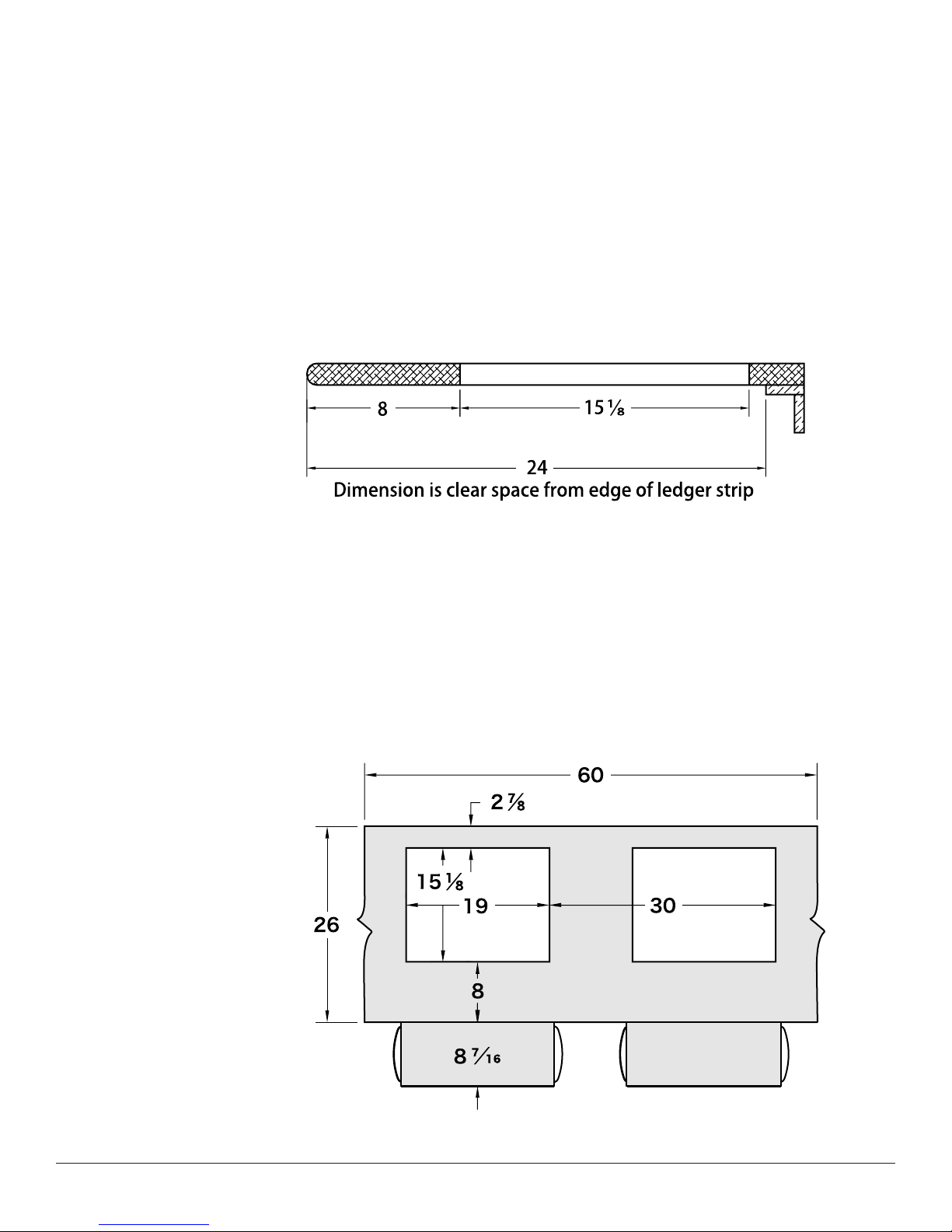
more flipIT units side-by-side, 30” spacing is recommended as a minim um.
The mouse tray extends on left or r ight. Seat users so left- and right-handed
do not conflict.
The recommended placement of the cutout f or the flipIT unit is 8 inches from the
user’s edge. This assumes a straight edge; not a round or contoured edge . If you
are experimenting with placement f
requesting additional templates and making dry-fit installations into scrap.
Based on this profile, a minimum of 24 inches of clearance, front to back, must be
allowed for the mechanism and LCD monitor. If you are installing modesty panels,
make sure you allow this clearance, as well.
or an unusual application, we recommend
Workstation Spacing
Use 30 inch spacing from
centerline to centerline, or from
common reference point as shown
on the drawing (from right edge of
cut-out to right edge of cut-out).
This drawing depicts a segment of
table top and does not
indicate a minimum table top
width.
FIK/FIH-23 for widescreens
cutout is 15-5/16” x 25” and
Keyboard is 26” wide including
mouse surface.
FIK/FIH-19 for widescreens
cutout is 15-5/16” x 20.62” and
Keyboard is 26” wide including
mouse surface.
flipIT Tech Line: 800 770-7042 3
© 2009 CBT Supply Inc.
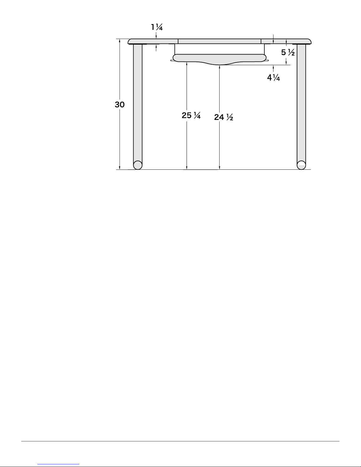
User Side Elevation
Desktop thickness may vary from no less than 3⁄4 inch to 1 1⁄4 inches. The suggested
position for installation of the keyboard L brackets is the 5th hole from the end, which
allows 1
tray assembly suspends 4 1⁄4 inches from the bottom surface. A 6-foot adult male
measures 23
11
⁄16 inches keyboard clearance and the user clearances shown. The keyboard
1
⁄2 inches from the top of the knee to the floor in sitting position.
Weight of LCD
Required for flipIT
to Close
For this very reason, the
pneumatic cylinder ships
partially installed.
If flipIT® is to be stored
without an LCD installed, it is
advised that the pneumatic
cylinder be disconnected for
ease of handling.
Top
Support
Flange
If no LCD is present, flipIT will remain open. The pneumatic cylinder is
loaded to counterbalance the weight of the LCD to open the unit.
the highest position possible to achieve optimum center of gravity: 1/2” or less clearance between the monitor and the lid rest flange . Several sets of holes, spaced 1/2”
apart, are provided to accommodate LCD variations. See page 14 for setting the
clearance.
Install the LCD in
4
© 2009 CBT Supply Inc.

Parts and Hardware
Parts List:
Prepare a place to unpack box contents, using a packing blanket, carpeting or
cardboard sheet to protect finished surfaces from damage. Before assembly,
take inventory of the parts included.
Qty 1 FlipIT Top Assembly with
grommet collar, VESA mount,
cables & pneumatic cylinder
Qty 4 Keyboard Assembly
Mounting Brackets
Qty 1 Keyboard Tray Assembly
(FIK-18 only)
Qty 1 VESA LCD mounting
bracket to be installed
on LCD using your
monitor’s screws
Qty 1 Cable release handle
(FIH-18 only)
Qty 4 Wood Screws, 3/4 inch for flipIT collar
Qty 4 Machine Screws, 1/4 in.
Qty 14 Wood Screws, 5/8 inch for Keyboard tray
& cable release
Qty 1 Paper template for top cut-out, shown positioned
for use.
flipIT Tech Line: 800 770-7042 5
Qty 1 Paper template for keyboard pilot holes, shown
positioned for use (FIK-18 only)
© 2009 CBT Supply Inc.
 Loading...