

CB Tech CB-VOC, CB-As Installation Manual
Installation Guide
CB-VOC
About the CB-VOC Drinking Water System
• The CB Tech CB-VOC Drinking Water System (CBVOC) is designed for
use on the countertop next to the sink, below the sink, or inline with
other devices.
• If installation or operation assistance is required, please contact your
Dealer. If Dealer is unavailable, please contact CB Tech at 866.622.9373.
Before You Begin
Please read this manual before proceeding with the installation and use
of your system. Installation, operation, and maintenance requirements are
essential to the performance of your system – failure to follow any instructions
or operating parameters contained herein may lead to product damage
or product failure.
1

• Replacement lters can be purchased directly from your Dealer.
• Check for compliance with any state or local laws and regulations
before use.
• If you are installing with a Below Sink Kit (CBK1), proceed to section
Below Sink Installation (Pg 2).
• If you are installing with a Countertop Kit (CBK2), proceed to section
Countertop Installation (Pg 16).
• If you are installing the system inline with existing plumbing, proceed to
section Inline Installation (Pg 19).
Part Numbers
Below Sink Installation
Below Sink Kit (CBK1) Required
2
Item #
1
2
3
4
5
6
7
8
9
10
11
12
13
14
*The acrylic base (Item #12) is an optional part available for purchase.
Part #
MC652
MC780
MC741
MC741
011-50-3011
MC273
CBTVOC
MC253
MC129
MC351S
MCB7-5D-18
011-25-4100
MC232
MC923LF
Part Description
Faucet assembly with blue tubing attached
Wing nut
Outlet adapter: connects to blue tubing
attached to faucet
Inlet adapter: connects to clear tubing
Housing top
Black rubber cushion (inside housing top)
Carbon Block Filter cartridge
V-band with knob
Bracket with two (2) metal bands
O-ring
Housing bottom
Tall acrylic base*
Clear tubing: connects inlet adapter to
plumbing
Adapta valve
3
1/2” slip joint nut
riser
angle stop valve
threading adapter
Adapta Valve
3/8” conguration
14
Adapta Valve
1/2” conguration
threading adapter
riser
angle stop valve
14
water supply
line with
Adapta
Valve in 3/8”
conguration
water supply
line with
Adapta
Valve in 1/2”
conguration
A
B
OR
tubing
from faucet
v-band
knob
1
2
3
4
5
7
8
10
11
12
6
9
13

Below Sink Kit Components
Included with the Below Sink Kit are the following components:
1. Adapta Valve: Used to connect the DWS to the cold water line below
the sink. The 1/4” clear tubing connects the Adapta Valve to the 1/4”
inlet tting on the DWS housing.
2. Faucet: The faucet installs on top of the sink or counter. The 1/4” blue
tubing connects the faucet to the 1/4” outlet tting on the DWS housing.
Recommended Installation Tools
NOTE: Included with each install kit are the xtures and accessories needed to
install the system. If you determine that your particular plumbing conguration
requires xtures different from those included with your shipment, please
contact your Dealer.
The following tools are recommended to install your DWS for below-sink use:
1. Installing the faucet on a ceramic/porcelain sink:
• 3/8” Reversible Electric Drill
• 7/16” High Speed Steel Drill Bit
• 1/2” Masonry Drill Bit
• Hammer
• Center Punch
• 8” Adjustable Wrench
• Pliers/Locking Pliers
2. Installing the faucet on a stainless steel sink:
• Everything from list #1, plus 1/8” high speed drill bit
3. Installing the faucet on a granite countertop:
• everything from list #1, plus the following:
a. hammer
b. center punch
c. plumbers putty
d. 1/2” diamond drill bit for granite
4. Installing the Adapta Valve:
• 8” Adjustable wrench
• Wire cutter or knife
4
Drill the Faucet Hole (if necessary)
The faucet can be installed through a standard faucet hole or spray hose
hole in your sink, if one is available. If no hole is available, use the following
instructions to drill a faucet hole. If a faucet hole is already available, skip to
section Connect the Faucet (pg 6).
1. Select and mark the faucet mounting spot on the sink.
a. Conrm that there are no reinforcing ribs under the desired faucet
location.
b. If you have an extra hole in your sink for a spray hose, you may also
choose to disconnect the spray hose and use that existing hole for
the CB-VOC faucet.
2. Use the hammer to gently tap the center punch on
the sink location where the hole is to be drilled. This
creates an indentation to mark the drilling location.
3. If you have a porcelain, ceramic, or cast acrylic sink:
CAUTION: Porcelain, ceramic, and cast acrylic
surface materials are extremely hard and can easily
crack or chip. Use extreme caution when drilling. CB
Tech is not responsible for any damages resulting
from faucet installation.
a. Use the 1/2” carbide-tipped masonry drill bit to grind away a small
section of sink veneer down to the metal, clearing enough space to
allow drilling without damaging the rest of the sink surface veneer.
b. Carefully use the 7/16” high-speed steel drill bit to completely drill a
hole through the metal sink.
CAUTION: Do not allow the drill bit to “grab” the sink veneer, as this will
damage the surface.
4. If you have a stainless steel or metal sink:
a. Use the 1/8” high-speed drill bit to
drill a pilot hole.
b. Use the 7/16” high-speed drill bit to
completely drill a hole through the
metal sink.
5
carefully grind
away porcelain
mark the spot

5. If you have a granite countertop:
CAUTION: Granite surface materials are extremely hard and can
easily crack or chip. Use extreme caution when drilling. CB Tech is not
responsible for any damages resulting from faucet installation.
a. Place a towel or basin under the sink, directly under the location of
the intended faucet hole.
b. Using a snake of plumbers putty, form a circular “dam” around
the location of the intended faucet hole. Make the dam 5” in
diameter and 3/4” tall.
c. Fill the dam with cool tap water. The water will keep the drill bit from
overheating.
d. Use the 1/2” granite drill bit to drill the hole. Slowly grind away the
granite material.
Connect the Faucet
Proceed to the instructions for your faucet type:
1. For a standard faucet, proceed to section Installing the Standard
Faucet (Pg 6).
2. For a capacity-monitored faucet, proceed to section Installing the
Capacity Monitor Faucet (Pg 8).
Installing the Standard Faucet
NOTE: The blue plastic tubing is attached to the faucet.
1. From the sink / countertop:
a. Place the larger soft black rubber washer over the faucet hole.
b. Place the cover plate on top of the large washer.
c. Place the smaller soft black rubber washer on top of the cover plate.
d. Place the faucet base over the smaller soft black rubber washer
and atop the cover plate.
2. From under the sink:
a. Slide the hard plastic black washer (with the smaller side up)
upward over the blue tubing.
b. Slide the lock washer upward, below the hard plastic washer.
c. Slide the wing nut upward, below the lock washer.
d. Hand-tighten the wing nut to secure the faucet.
6
7
cover plate
countertop
plastic washer
wing nut
large black washer
lock washer
blue tubing
small black washer
Complete Faucet
Assembly with
Blue Tubing
(MC652)
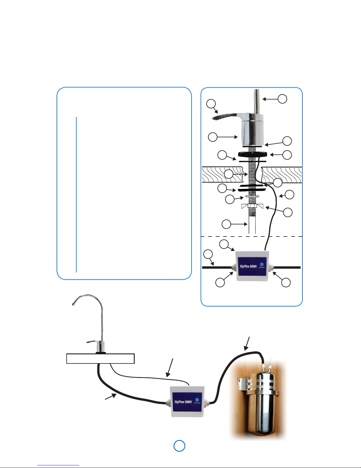
Installing the Capacity Monitor Faucet
NOTE: In addition to the blue plastic tubing attached to the faucet. A
separate piece of blue tubing is included for connection between the
housing OUTLET port and the Filter Monitor Unit INLET port.
blue tubing
from faucet
black wire
from capacity
indicator plate
tubing for
housing
countertop
Capacity Monitor
Assembly
1
3
6
79
4
5
12
13
8
2
14
5
1515
11
10
8
1
2
3
4
5
6
7
8
9
10
11
12
13
14
15
Faucets with Capacity
Monitor Include:
Spout
Faucet handle
Faucet base
Faucet stud
Blue tubing
(attached to faucet)
Small rubber washer
LED Display Plate
Black wire
(attached to LED display plate)
Large rubber washer
Black track washer
Hard plastic washer
Lock washer
Wing nut
Filter Monitor Unit
(2) Filter monitor adapters
(MC744)
 Loading...