

CB Radios DX 949 Service Manual

DX 949
CHAPTER 1
SPECIFICATIONS
1.0 General. . . . . . . . . . . . . . . . . . . . . . . . . . . . . . . . . . . . . . . . . . . . . . . . . 2
1.1 Transmitter. . . . . . . . . . . . . . . . . . . . . . . . . . . . . . . . . . . . . . . . . . . . . . 2
1.2 Receiver. . . . . . . . . . . . . . . . . . . . . . . . . . . . . . . . . . . . . . . . . . . . . . . . 2
TABLE OF
CONTENTS
PAGE
CHAPTER 2
OPERATION
2.1 Control & Connections. . . . . . . . . . . . . . . . . . . . . . . . . . . . . . . . . . . . 3
2.1.1 Front Panel . . . . . . . . . . . . . . . . . . . . . . . . . . . . . . . . . . . . . . . . . . . . 3
2.1.2 Rear Panel . . . . . . . . . . . . . . . . . . . . . . . . . . . . . . . . . . . . . . . . . . . . 6
2.1.3 Frequency Chart. . . . . . . . . . . . . . . . . . . . . . . . . . . . . . . . . . . . . . . . . 7
2.2 Microphone. . . . . .. . . . . . . . . . . . . . . . . . . . . . . . . . . . . . . . . . . . . . . 8
2.3.1 Procedure To Receive . . . . . . . . . . . . . . . . . . . . . . . . . . . . . . . . . . . . 8
2.3.2 Procedure To Transmit . . . . . . . . . . . . . . . . . . . . . . . . . . . . . . . . . . . 8
2.4 Alternate Microphones And Installation. . . . . . . . . . . . . . . . . . . . . . . 8
CHAPTER 3
CIRCUIT DESCRIPTION
3.0 Introduction . . . . . . . . . . . . . . . . . . . . . . . . . . . . . . . . . . . . . . . . . . . 11
3.1 PLL Circuit . . . . . . . . . . . . . . . . . . . . . . . . . . . . . . . . . . . . . . . . . . . 11
3.2 Receiver Circuit . . . . . . . . . . . . . . . . . . . . . . . . . . . . . . . . . . . . . . . . 11
3.3 Transmitter Modulation Circuit . . . . . . . . . . . . . . . . . . . . . . .. . . . . . 11
3.4 Transmitter Amplifier Circuit . . . . . . . . . . . .. . . . . . . . . . . . . . . . . . . 11
CHAPTER 4
ALIGNMENT
4.0 Required Test Equipment. . . . . . . . . . . . . . . . . . . . . . . . . . . . . . . . . . 14
4.1 Alignment Procedures . . . . . . . .. . . . . . . . . . . . . . . . . . . . . . . . . . . . . 14
4.1.1 PLL Alignment . . . . . . . . . . . . . . . . . . . . . . . . . . . . . . . . . . . . . . . . . 14
4.1.2 Transmitter Alignment . . . . . . . . . . . . . . . . . . . . . . . . . . . . . . . . . . . 15
4.1.3 Receiver Alignment . . . . . . . . . . . . . . . . . . . . . . . . . . . . . . . . . . . . . 16
CHAPTER 5
MAINTENANCE
5.0 Precautions . . . . . . . . . . . . . . . . . . . . . . . . . . . . . . . . . . . . . . . . . . . . 19
5.1 Periodic Inspection . . . . . . . . . . . . . . . . . . . . . . . . . . . . . . . . . . . . . 19
5.2 Fuse Replacement . . . . . . . . . . . . . . . . . . . . . . . . . . . . . . . . . . . . . . . 19
CHAPTER 6
DIAGRAMS AND PART LIST
6.0 PCB Layout & Part List. . . . . . . . . . . . . . . . . . . . . . . . . . . . . . . . . . . 20
Updates and Corrections. . . . . . . . . . . . . . . . . . . . . . . . . . . . . . . . . . . . . . . . . . . 32
- 1 -

DX 949
1.0 GENERAL
Model DX 949
Frequency Range 26.965 - 27.405MHz.
Emission Modes AM/USB/LSB
Frequency Control Phase Lock Loop (PLL) synthesizer.
Frequency Tolerance
Frequency Stability
Operating Temperature Range
Microphone Plug-in dynamic; with push-to-talk switch and coiled
Input Voltage
Current Drain : Transmit (AM full mod.) <3.5A.
Current Drain : Receiver (Squelched) <0.5A.
(Max. audio output) <1.0A.
Antenna Connector UHF, SO239.
Dimensions 2-3/8”(H) x 7-7/8”(W) x 9-1/4”(D).
Weight 5 lb.
1.1 TRANSMITTER
RF Power Output AM : 4W SSB : 12W
RF Transmit Modes AM/SSB
Modulation High and low level Class B, Amplitude Modulation :
Spurious Emissions -55 dB.
Carrier Suppression -55 dB.
Audio Frequency Response 300 to 2500Hz
Antenna Impedance 50 Ohms.
Output Indicators Meter shows relative RF output power, SWR and AM
1.2 RECEIVER
Sensitivity For 10dB S/N (AM)
Sensitivity For 10dB S/N (SSB)
IF Frequency AM : 10.695 MHz 1st IF, 455 KHz 2nd IF.
Image Rejection -65 dB.
Adjacent Channel Selectivity -60 dB.
RF Gain Control 45 dB adjustable for optimum signal reception.
Automatic Gain Control (AGC) Figure Of Merit 100 mV for 10 dB Change in Audio Output
Squelch
Noise Blanker RF type.
Audio Output Power 2 watts into 8 Ohms.
Audio Frequency Response AM and SSB : 300 to 2500 Hz.
Built-in Speaker 8 Ohms, round.
External Speaker (Not Supplied) 8 Ohms; disables internal speaker when connected.
CHAPTER 1
SPECIFICATIONS
± 0.005 %.
± 0.001 %.
-30°C to +50°C.
cord.
13.8V DC nominal ±15%.
(SPECIFICATIONS SUBJECT TO CHANGE WITHOUT NOTICE)
AM and SSB
Modulation. Transmit LED glows red when
transmitter is in operation.
<0.5µV
<0.25µV.
Adjustable; threshold less than 0.5 µV.
- 2 -
DX 949
CHAPTER 2
OPERATION
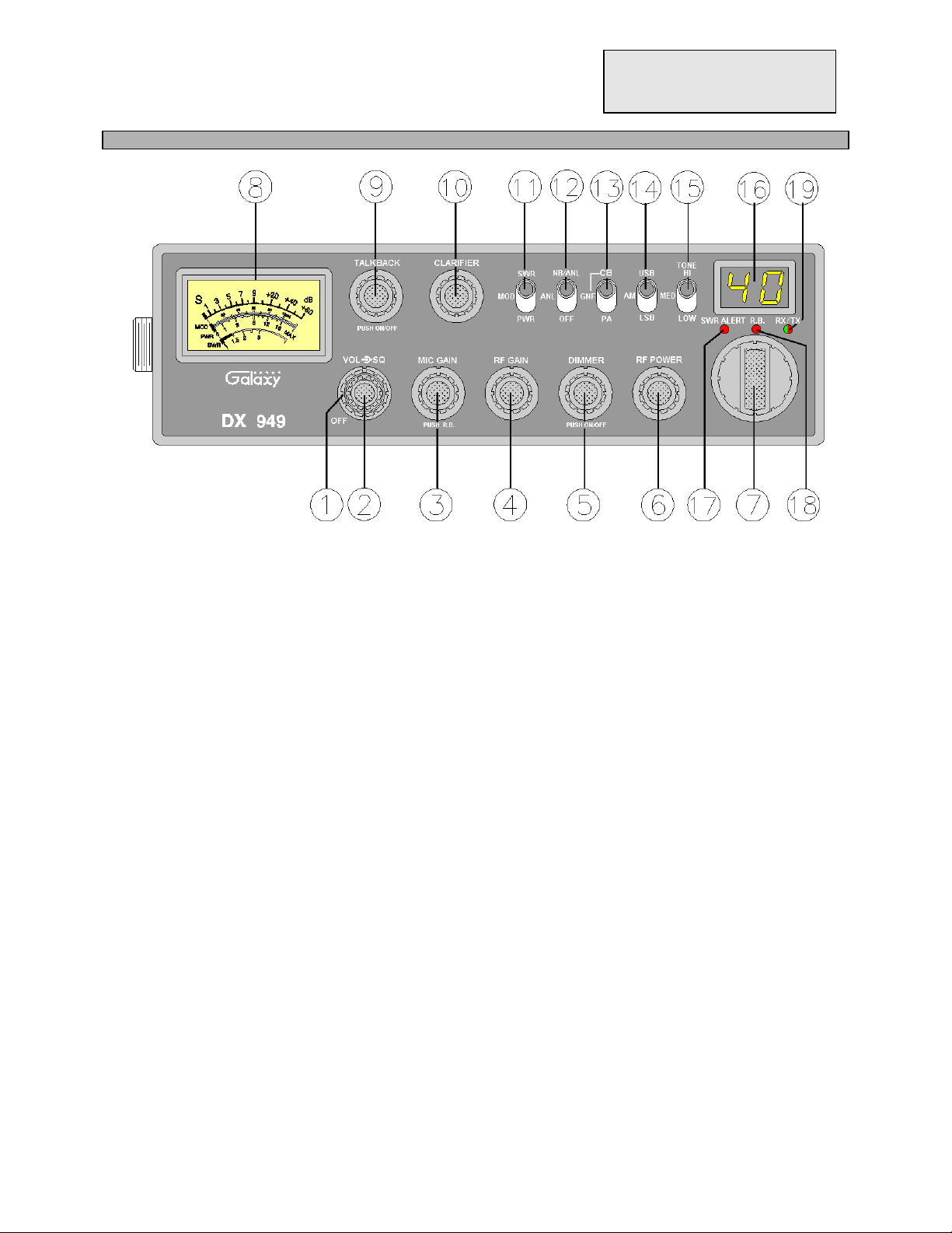
Figure 2-1 Front Panel
2.0 INTRODUCTION
This section explains the basic operating procedures for the Galaxy DX 949 mobile transceiver.
2.1 CONTROL AND CONNECTIONS
2.1.1 FRONT PANEL
Refer to the above Figure 2-1 for the location of the following controls.
1. SQUELCH CONTROL
This control is used to control or eliminate receiver background noise in the absence of an
incoming signal. For maximum receiver sensitivity, it is desired that the control be adjusted only
to the point where the receiver background noise is eliminated. Turn fully counter-clockwise, then
slowly clockwise until the receiver noise disappears. Any signal to be received must now be
slightly stronger than the average received noise. Further clockwise rotation will increase the
threshold level which a signal must overcome in order to be heard. Only strong signals will be
heard at a maximum clockwise setting.
2. ON/OFF VOLUME CONTROL
Turn clockwise to apply power to the radio and to set the desired listening level.
3. MIC GAIN
- 3 -

Adjusts the microphone gain in the transmit and PA modes. This controls the gain to the extent that
full talk power is available several inches away from the microphone. In the Public Address (PA)
mode, the control functions as the volume control. Pushing this knob turns the Roger Beep on and
off. When the Roger Beep is on, the radio transmits an audio tone at the end of your transmission.
This indicates the end of your transmission so that people who are having trouble hearing you will
know that you are done speaking. As a courtesy to others, use the Roger Beep only when necessary.
4. RF GAIN CONTROL
This control is used to reduce the gain of the receive amplifier under strong signal conditions.
5. DIMMER CONTROL
This knob controls the level of brightness for the meter lamp and the LED channel display. Also,
pushing this knob turns the meter lamp and the display LED’s on and off.
6. RF POWER CONTROL
This control allows the user to adjust RF power output.
7. CHANNEL SELECTOR
This control is used to select a desired transmit and receive channel.
8. FRONT PANEL METER
The Front Panel Meter allows the user to monitor signal strength, RF output power, SWR level and
AM modulation level.
9. TALKBACK CONTROL
Pushing this knob turns the Talkback circuit on and off. Adjust this knob for desired volume of
Talkback. This is used to monitor your own voice. For example, you could use this feature to
compare different microphones.
10. CLARIFIER
Allows tuning of the receive frequency above or below the channel frequency by up to 1.0 KHz.
Although this control is intended primarily to tune in SSB signals, it may be used to optimize AM
signals .
11. SWR/MOD/ PWR SWITCH
This switch controls the function of the meter during the transmit mode. In the SWR position, the
meter indicates the Standing Wave Ratio (SWR) of your antenna. There are no adjustments because
the SWR circuit in this radio calibrates itself automatically. When the switch is in the MOD
position, the green scale on the meter indicates your percentage of modulation. This operates in AM
only, not in SSB. When this switch is in PWR position, the meter indicates your power output.
12. NB/ANL/OFF SWITCH
In the ANL position, the Automatic Noise Limiter is activated. When the switch is placed in the
NB/ANL position, the RF Noise Blanker is also activated. The Noise Blanker is very effective in
eliminating repetitive impulse noise such as ignition interference.
13. PA/GNF/CB SWITCH
- 4 -

In the PA position, your voice will come out of the speaker that you need to plug in to the PA. SP.
jack on the rear panel. The radio does not operate when you are in the PA mode. The CB mode is
normal operation of the radio. In the GNF mode, you are in CB operation but the Galaxy Noise
Filter is engaged. This is a special noise filter that de-emphasizes audio high frequency response in
order to increase the signal-to-noise ratio of weak signals. While you will notice a dramatic
reduction in the “rushing” sound when this filter is activated, it does not have much effect on the
signal-to-noise ratio of strong signals. It is mostly used for SSB reception.
14. MODE SWITCH
This control allows you to select one of the following operating modes : USB/AM/LSB .
15. TONE SWITCH HI/MED/LO
This switch changes tone quality in receive only. In LO position, bass is increased and in HI
position, treble is increased.
16. CHANNEL DISPLAY
The channel display indicates the current selected channel.
17. SWR ALERT LED
This LED lights red when your SWR is higher than about 3:1. This is not an exact indicator of 3:1
SWR, but it is an indication that you should check your SWR reading.
18. R.B. LED
This lights green when the Roger Beep is on.
19. RX/TX LED
This LED lights green during receive and red during transmit.
2.1.2 REAR PANEL
- 5 -
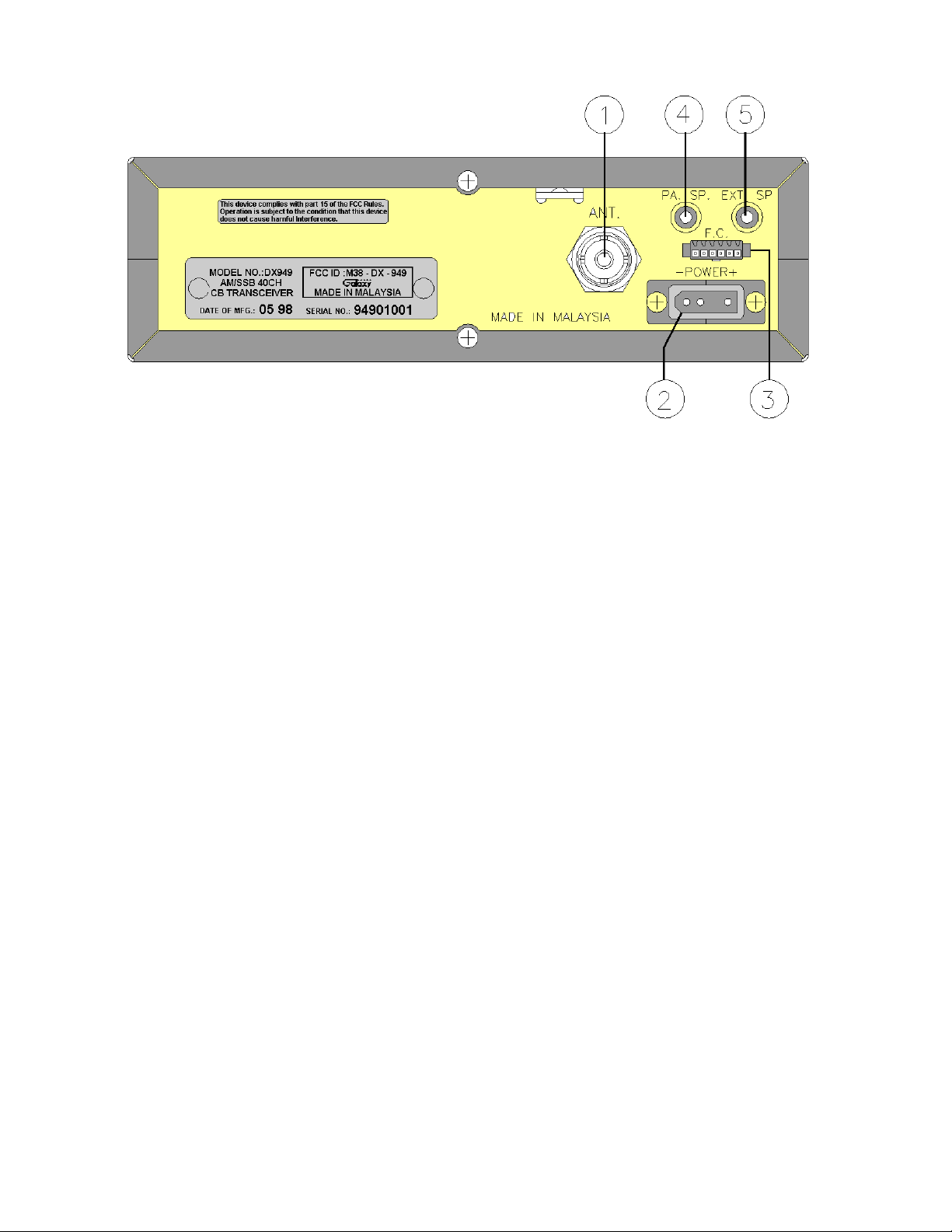
Figure 2-2 represent the location of the following connections :
Figure 2-2 Rear Panel
1. ANTENNA
This jack accepts 50 ohms coaxial cable with a PL- 259 type plug.
2. POWER
This connector accepts 13.8V DC power cable with built-in fuse. The power cord provided with the
radio has a black and red wire. The black goes to negative and the red goes to positive.
3. FREQUENCY COUNTER CONNECTOR
This connector is for the optional Galaxy FC 347 six digit frequency counter. All connections are
made through this connector. No soldering is required.
4. PA. SP.
This jack is for PA operation. Before operating, you must first connect a PA speaker ( 8 ohms, 4W )
to this jack.
5. EXT. SP.
This jack accepts 4 to 8 ohms, 5 watts external speaker. When the external speaker is connected to
this jack, the built-in speaker will be disabled.
2.1.3 FREQUENCY CHART
- 6 -

CHANNEL CHANNEL FREQUENCY CHANNEL CHANNEL FREQUENCY
1 26.965 MHz 21 27.215 MHz
2 26.975 MHz 22 27.225 MHz
3 26.985 MHz 23 27.255 MHz
4 27.005 MHz 24 27.235 MHz
5 27.015 MHz 25 27.245 MHz
6 27.025 MHz 26 27.265 MHz
7 27.035 MHz 27 27.275 MHz
8 27.055 MHz 28 27.285 MHz
9 27.065 MHz 29 27.295 MHz
10 27.075 MHz 30 27.305 MHz
11 27.085 MHz 31 27.315 MHz
12 27.105 MHz 32 27.325 MHz
13 27.115 MHz 33 27.335 MHz
14 27.125 MHz 34 27.345 MHz
15 27.135 MHz 35 27.355 MHz
16 27.155 MHz 36 27.365 MHz
17 27.165 MHz 37 27.375 MHz
18 27.175 MHz 38 27.385 MHz
19 27.185 MHz 39 27.395 MHz
20 27.205 MHz 40 27.405 MHz
2.2 MICROPHONE
- 7 -

The receiver and transmitter are controlled by the push-to-talk switch on the microphone. Press the
switch and the transmitter is activated, release switch to receive. When transmitting, hold the
microphone two inches from the mouth and speak clearly in a normal voice. The radio comes
complete with low impedance (500 ohm) dynamic microphone. For installation instructions of the
microphone, see section “ALTERNATE MICROPHONES AND INSTALLATION”.
2.3 OPERATION
2.3.1 PROCEDURE TO RECEIVE
1. Be sure that power source, microphone and antenna are connected to the proper connectors
before going to the next step.
2. Turn unit on by running
3. Set the
4. Set the
5. Listen to the background noise from the speaker. Turn the SQ knob slowly clockwise until the
noise just disappears. Leave the control at this setting. This SQ is now properly adjusted. The
receiver will remain quiet until a signal is actually received. Do not advance the control too far or
some of weaker signals will not be heard.
6. Set the
7. Set the
2.3.2 PROCEDURE TO TRANSMIT
1. Select the desired channel of transmission
2. Set the
3. If the channel is clear, depress the push-to-talk switch on the microphone and speak in a normal
voice.
to a comfortable listening level.
VOL
MODE
CHANNEL
gain control fully clockwise for maximum receive gain.
RF
MIC GAIN
knob clockwise on transceiver.
VOL
switch to the desired mode.
selector switch to the desired channel.
control fully clockwise.
2.4 ALTERNATE MICROPHONES AND INSTALLATION
For best results, the user should select a low impedance dynamic type microphone or a
transistorized microphone. Transistorized type microphones have a low output impedance
characteristic. The microphones must be provided with a four-lead cable. The audio conductor and
its shielded lead comprise two of the leads. The third lead is for transmit control and the fourth is
for receive control. The microphone should provide the functions shown in schematic below
(Figure 2-3).
4 WIRE MIC CABLE
- 8 -
Pin Number Mic Cable Lead
1 Audio Shield
2 Audio Lead
3 Transmit Control
4 Receive Control
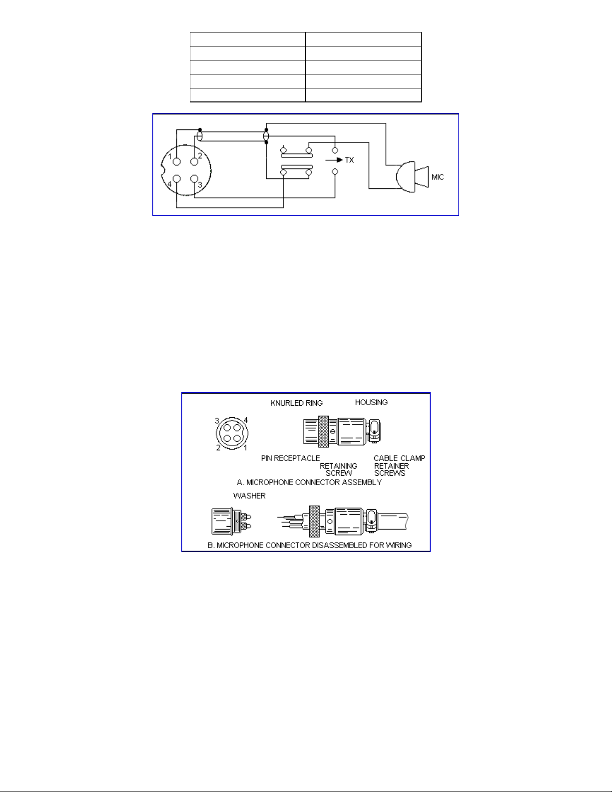
Figure 2-3 Your Transceiver Microphone Schematic
If the microphone to be used is provided with pre-cut leads, they must be revised as follows :
(i) Cut leads so that they extend 7/16” beyond the plastic insulating jacket of the microphone cable.
(ii) All leads should be cut to the same length. Strip the ends of each wire 1/8” and tin the exposed
wire.
Before beginning the actual wiring read carefully, the circuit and wiring information provided with
the microphone you select. Use the minimum head required in soldering the connections. Keep the
exposed wire lengths to a minimum to avoid shorting when the microphone plug is reassembled.
Figure 2-4 Microphone Plug Wiring
- 9 -
 Loading...