

Page 1
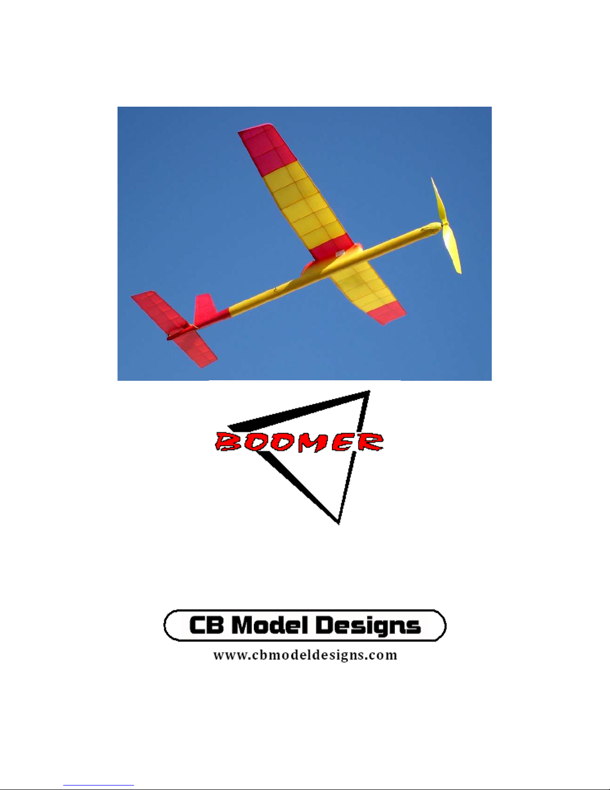
Construction Manual
Mark II
Kit No. CBMD-001
Copyright CB Model Designs 2009
Page 2

2
Thank you for purchasing a Boomer kit. We hope you will find building and flying the
Boomer one of the pleasurable things in life and achieve many hours of enjoyment from
it.
Every effort has gone into making the Boomer one of the lightest high performance P-30
models available. Each kit has been fabricated from select wood for a light airframe that
can meet the minimum 40 gram airframe weight for this event. The resulting model is
suitably strong for the intended purpose of soaring in light lift. It is an excellent transition
model for free flight competition and just plain fun sport flying .
Adhesive and general assembly process recommendations
Cyanoacrylate adhesive (CA in this instruction) is should be used with discretion and
caution. Assembly of the basic structures is best achieved with white glue or cellulose
cement (Duco, Testors, Ambroid, etc.). Use of these types of adhesive offer the best
chance for any minor adjustment during assembly, and minimizes the chance of adhering
the structure to the plan or building board by thin glue wicking through pin holes in the
wax paper covering the plan. This in turn reduces the chance of part damage when
removing a structure assembly from the plan when complete. All parts should be preassembled dry before any bonding occurs to check for proper location and fit. Proceed
carefully and take your time with the assembly process. A Boomer can easily be
constructed and made ready to fly in one week of evening work sessions.
Wing Assembly
Separate all the wing parts from the laser cut sheets. Note that three of the W-1 ribs
include a spar notch near the trailing edge. These ribs are installed at the wing center and
to either side to support the short spar installed there that resists covering damage from
the wing installation bands. Keep these items separate to avoid installing them in the
wrong part of the wing during the build.
Start wing construction by building leading and trailing edge assemblies. The drawing
shows a 1/32 X 3/32 hard balsa cap bonded to the forward side of TE-1 and TE-2. This is
shown as a method of providing some additional stiffness for the trailing edges after they
are final shaped. Glue them onto the forward edges of TE-1 and TE-2 in one piece
segments. Once the glue has dried, sand the cap flush to the trailing edge thickness and
carefully cut the caps at the notches for the wing ribs.
Cover the construction drawing with wax or parchment paper to prevent parts from
sticking during assembly. The use of balsa strips 1/8” thick x ¼” or wider is suggested
as boundary control to the wing plan form outline. Pin this material at the edge line for
TE-1 to start. The wing tip panels have washout built in during construction, and TE-2
will not be held against the building board during assembly as done for TE-1. Use thicker
balsa to provide a boundary edge that still controls the plan form location of TE-2 while
it is rigged for washout during assembly. The LE-1 and LE-2 parts can be controlled for
plan form alignment in the same fashion as done for the trailing edge segments. Position
CBMD-001 Rev B
Page 3

3
LE-1, LE-2, TE-1 and TE-2 parts on the plan for alignment. Note that the LE-1 and LE-2
parts have ends cut at an angle for dihedral. Be sure to locate these parts with the angled
ends up at the dihedral joints. Pinning through these parts is not recommended; use scrap
balsa blocking to press the parts against the boundary strips, and pins through these to
secure part locations.
Assemble the tip gusset T-2 to the outboard end of TE-2 with the parts against the plan
for alignment. Use a piece of wood blocking pinned to the plan at the inboard line of the
T-1 rib to provide a reference surface for the forward and aft gussets. Glue the T-2
gusset against TE-2 with the T-1 side against the blocking. Similarly, bond one T-3
gusset against the aft side of LE-2 against the plan for alignment, and against the T-1
blocking. Bond the second T-3 gusset on top of the first to make up the 3/16” thickness
in this area for T-3.
At the inboard ends of TE-1 and LE-1, glue in the WG-1 parts to complete the
subassemblies for the wing edges.
Position spars WS-1 and WS-2 in place over the plan. Use scrap balsa blocking pinned
into the building board between the rib locations to maintain the spar position forward
and aft. Make sure the spar stand-off tabs are against the plan. Begin assembly by dry
fitting the W-1 ribs over the spars notches and into the TE-1 notches. Adjust the
position of the spar segments and trailing edges to achieve best fit of all parts to the
drawing. Dry prefit the tip panel next. Note that all the tip ribs have standoff tabs to
support the trailing edge of the rib in proper location for washout. TE-2 is shimmed up
until it is flush to the upper edge of each tip panel rib. Position a 1/16” shim on the
inboard side of W-4, another 3/32 shim in between W-4 and W-5, and a 1/8” shim at the
tip of TE-2 to support the trailing edge during assembly.
Prefit the T-1 rib next, with the TE-2 shimmed for washout as controlled by the ribs
already positioned. Cut off the end of WS-2 and LE-2 to match the joint as shown on the
plan and with T-3 gussets respectively. Position the T-1 rib for best fit forward and aft,
making sure there is sufficient material to clean up at the trailing edge when wing sanding
is performed.
When satisfied that all parts are aligned and fitting properly, carefully bond the wing
assembly together. Do not install the W-1 ribs at the wing center and polyhedral joints
yet; these will be installed when the dihedral is added. The W-1 ribs tails include a small
rectangular boss in the rib profile. This controls the position of the rib end for location
relative to the finished shape of the airfoil through the trailing edge. The boss should be
seated against the plan on the lower edge when installed. TE-2 is installed with the upper
side flush to the upper edge of ribs W-2 through W-5 and T-1 with the inboard end at the
dihedral joint touching the plan.
Install the 1/16” square stiffeners on either side of each rib at the trailing edge of the
wing. These are ¾” long, and installed to be a little above the rib profile as shown in
CBMD-001 Rev B
Page 4

4
View D-D on the drawing. Don’t trim the tapers yet-this is done as part of the wing
sanding process. The stiffeners add strength to keep the trailing edge from twisting as
well as prevent buckling of the thin rib sections from the wing tissue covering tension.
Add the 1/16” square turbulator spars next. At the dihedral and polyhedral joints, allow
½” overlap of the spars to allow the scarf joint to be made when the dihedral is added.
Again, no W-1 rib is installed yet in these locations.
Remove the tip panel from the drawing carefully. Using a fine sanding block, VERY
LIGHTLY sand a shallow bevel at the end of TE-2 and LE-2 where they join the inboard
wing panel and form the dihedral joint. The material cross section is so small there is
very little sanding required-you can easily overdo this. Note the color change at the end
of these parts to judge how much material is removed. Carefully rig the tip panel at the
dihedral dimension for the tip shown on the plan and inspect the resulting joint at TE-1
and TE-2 and also the LE-1 and LE-2 for little or no gap. If this area became over
sanded, a small filler of balsa can be added during the bonding process to correct.
Move the tip panel out of the way to install the W-1 rib onto the inboard wing panel still
on the board. Carefully tilt and slip into place under the excess turbulator spar ends and
onto the WS-1 end that is notched to fit. Check the alignment to LE-1 and TE-1.
Position the outboard rib angle gauge against WS-1 and W-1 to provide the tilt toward the
inboard side of the wing. Check alignment of the rib for being on center to the dihedral
joint, and bond in place; do not glue in the turbulator spars yet..
Place the tip panel back into position with dihedral as shown on the drawing. Plan form
align to the drawing using the blocking to trap the tip panel in place. Make sure the end
of WS-2 is correctly against the end of WS-1, and the LE and TE joints are touching.
Once satisfied, bond the inboard end of WS-2 to WS-1 and W-1; LE and TE joints. The
turbulator spars should still be left with the excess on either side of W-1, and nothing
glued into the notches in W-1 yet. Add the 1/16” square stiffeners at the W-1 rib trailing
edge at the dihedral joint.
The next step requires a very sharp, fine razor to perform. Do not attempt with a #11
knife blade. One half of a new double edge razor is recommended, although a extra fine
single edge razor is almost as good. The process requires light pressure and a very fine
blade is best used to perform the cut.
At the dihedral joint, the turbulator spars are overlapped on top of each other, with the
lower one positioned in the W-1 notch. Using the razor , slice down through the stack of
spar material at a diagonal similar to what is shown on the plan, centered on rib W-1.
The resulting scarf joint should slip into the W-1 notch, straddling the rib. Bond this in
place and repeat for the rest of the spars. Direction of the scarf joint is not important,
only that the joint has no gap and is a shallow angle as shown on the drawing to transfer
wing bending loads effectively. If a gap manifests in the joint after cutting, make a filler
CBMD-001 Rev B
Page 5

5
from thin balsa that can regain contact with both joint surfaces and bond in place. Cut the
excess fill material off after the glue has dried. Resist all urges to add additional doublers
at the dihedral joints. This wing has never had a failure at these joints the entire time this
design was being test flown and used for competition flying, including some very hard
crashes. Good joint quality is a must!
After both tip panels are rigged for dihedral, follow a similar procedure to rig one half of
the wing to the dihedral angle shown. Add the short 1/16” square support spars common
to the three W-1 ribs at the wing center; this completes the wing structural assembly.
Wing sanding and shaping
Begin shaping the wing by profiling the wing tip leading edge to blend into T-1 and
match the radius shown on the plan. Clean up the wing edge profile to remove any
mismatches and inconsistencies. Remove the stand-off tabs from the spars, tip panel ribs
and T-1.
Make a contoured sanding block to use for light sanding of the wing underside. On a
scrap balsa block 1” wide, carefully trace the bottom profile of rib W-1 using the cutout
in the scrap laser cut sheet as a template. Saw this profile into the block with a band saw,
scroll saw, etc. An alternate method is to make a series of balsa templates cut to the same
profile and assemble into a contoured block at least 1” wide. To the contoured surface
bond a strip of 120 grit sandpaper the same width as the block. On the opposite side bond
another strip that would be a flat surface to use for sanding all other areas of the wing.
Also useful for getting into small areas for shaping are small emery boards.
Start the wing sanding and shaping on the underside to start. Sand the lower surface of
the leading edges to be flush with the lower edges of the ribs. Then sand the underside of
the trailing edges to remove the step condition relative to the lower rib profiles and
continue the airfoil contour into the trailing edge. Care should be taken when shaping the
trailing edge not to over sand, as this area becomes fairly thin in cross section when
finished. The best way to sand these areas is to place the wing upside down against a flat
surface that allows one section of the trailing edge to be held flat against it while the
adjacent areas with dihedral are allowed to drape off either side. Typically this would be
the corner of a table or other raised working surface that will allow the other areas of the
wing to be in the clear as you restrain the one section of wing for shaping.
Use the flat side of your sanding block and carefully sand just the trailing edge material
until the step condition is removed at the forward edge and the rib contours are flush to
the surface of TE-1 or TE-2. Hold the wing carefully by lightly pressing against a few of
the ribs near the trailing edge with one hand to keep the wing structure from flexing
sideways as you proceed with sanding. You may wish to color the lower surface of the
trailing edge before you begin sanding to see how much material is being removed. The
aft edge of TE-1 or TE-2 should be left as stock thickness in the resulting sanded
contour. Repeat this process for each of the remaining trailing edge segments
CBMD-001 Rev B
Page 6

6
Once the leading and trailing edges have been blended flush to the rib contours, use the
contoured side of the sanding block to very lightly touch up any areas of the under camber
for flush condition at the lower edge of the rib and wing spar joints. Make sure the wing
spars are flush with the W-1 rib at each dihedral joint. Work the underside of T-1 to be
smooth and flush with WS-2 and TE-2 / T-2 contours. Leave T-1 as a rectangular cross
section for now.
Shape the upper surface of the wing by sanding down the LE-1 and LE-2 contours to be
flush with the rib edges for the upper side. At the dihedral joints the emery board may be
more useful to shape the areas adjacent to this area. Once the leading edges are blended
flush with both the upper and lower rib profiles, finish the leading edge radius to a fairly
sharp blend-approximately .06 radius or what is shown on the wing cross section on the
drawing. Use the flat side of the sanding block to carefully sand down the tops of the
turbulator spars to level these in to the contour of the wing-it doesn’t take much sanding
here. Blend the top of T-1 lightly to complete the necessary profiling to fair this in with
the wing contour. Now blend off the tops of the TE-1 and TE-2 segments until flush with
the tops of the ribs and any of the projecting 1/16” square stiffeners sanded flush as well.
Again, this is best performed by holding one section of wing at a time against the
workbench edge and carefully sanding just the top of the TE- or TE-2 to locally shape and
refine until the wing contour is represented. The trailing edge will be fairly thinapproximately 5/32” thick at the forward side when all shaping is completed. Finish
profiling the 1/16” stiffeners at the ends of the ribs to the tapered condition shown on the
drawing, using a sharp razor and sanding to final plan view profile.
Using a small piece of 120 grit sandpaper for fine shaping all areas of the wing and
blending corners. The lower outboard edge of T-1 is radius blended to the upper
outboard edge to remove all boxiness to T-1 and provide a streamlined shape to the
wingtip. Continue to finish sand the wing with 220 and 320 grit paper until you are
satisfied with the smoothness of the result.
Finish the wing substructure with one coat of full strength nitrate dope, lightly sanded
with 320 grit when dry. Follow this with an additional full strength coat of dope to seal
the grain where the covering is to be adhered. This means the entire framework on the
lower surface of the wing needs to be edge sealed, as the tissue covering will be adhered
to each rib and spar to maintain the under cambered airfoil contour. Seal the entire
leading and trailing edge, top and bottom. Seal the T-1 rib completely and edge seal the
tops of the ribs at the dihedral joints. Any additional tissue color breaks based on the
wing structure should also be sealed to allow tissue attachment at these locations. If you
plan to cover with MicroLite or other heat shrink covering, follow the manufacturers
recommendations for preparing the surfaces for covering.
Horizontal stabilizer assembly
Construction of the horizontal stabilizer begins with assembly of the 1/32 ply S-2A
doublers with ribs S-2; make sure these are assembled as opposites. Use center rib S-1 as
a template to establish location of S-2A. Align the spar slots in S-1 and S-2 to index
CBMD-001 Rev B
Page 7

7
together and lightly trace against the forward edge of S-1 to mark the forward edge
location of S-2A. Bond S-2A in place to the line and flush to the rib bottom. Install the
filler SF-1 at the top of S-2A at this time as well. Bevel the forward edge after
installation to mate with the back surface of the S-7 closeout as required.
Use the same method to control the plan form boundary of the stab assembly as done for
the wing. Position the STE-1, SLE-1, ST-1 and SS-1 parts on the plan. Dry fit all the
ribs and adjust everything for best fit to the drawing. Use blocking to control the inboard
faces of S-2 that project forward of the S-7 closeout to maintain good alignment with the
fuselage stab platform. Glue in the gussets S-2 and S-3, and the ends of SS-1 into the
notch in ST-1 on either end of the stab.
Glue in the ribs starting with S-1 followed by S-2 on either side. On S-7, sand a bevel on
the bottom edge to allow this to sit flush to the building surface. Glue S-7 to the front
edge of the S-2A doublers and front edge of S-1. Glue in the remaining ribs.
When dry, remove from the plan and shape the leading and trailing edges to shape, etc.
Do a fine sanding to cleanup overall, then apply two coats of nitrate dope as done for the
wing. The stabilizer is covered before the filler SF-2 and plywood strike plate are
installed. Do not cover until you have done a pre-fit of the stabilizer with the stab
platform on the fuselage.
Vertical stabilizer assembly
The fin assembly is straightforward-just assemble over the drawing using the laser cut
parts. When dry, sand the F-1 segment to a tapered shape as shown in the plan view of
the fuselage, and round off the rest of the fin outline. Apply two coats of dope to the
outline parts after fine sanding and then cover with tissue provided or the covering
material of your choice.
Fuselage assembly
The fuselage assembly is largely complete as received. As noted previously, perform a
prefit of the stabilizer assembly on the platform. Check for freedom of movement to
allow the D/T pop-up to have complete range of motion required. There should not be a
snug fit to the platform-some very slight side to side freedom of movement should be
present when in the flying position. The stab covering overlap onto the inboard face of
S-2 will take up some of this gap so be mindful of this when fine tuning the fit, if
required. If the gap is tight, remove material from the ends of the stab platform using a
sanding block until the proper fit is achieved. If desired, the upper surface of the filler on
the stab platform can be sanded down to be flush with the stab contour at this time.
If you are planning to use a Gizmo-Geezer or Ikara P-30 front end, check the fit and make
any adjustments necessary to install these items. The drawback on these are the extra
weight they add, but they do offer ease of thrust adjustment.
Decide which timer you are going to use. The Ikara timer option is simply glued over the
CBMD-001 Rev B
Page 8

8
hole in the pylon at the location shown. If you plan to use one of the other two timer
options, a 1/32 ply adapter plate is provided for you to glue in place by aligning to the
hole in the pylon. Install the Ikara timer after finishing the fuselage.
Install the D/T trip wire assembly as shown on the drawing. Use the laser cut fillers to
fair in the tube and strengthen the joint. The filler can be tapered to a feather edge if
desired to reduce weight and offer some streamlining. Install the timer spring tension
adjustment tube as shown in a similar manner as done for the trip wire.
Do any fine sanding you feel is necessary on the fuselage and apply two coats of thinned
nitrate dope over all the exposed areas, including the entire stab platform. The inside of
the motor tube was sealed with dope before forming, so there is no need to do anything
on this area. Sand with 320 grit between coats to remove any fuzz that stands up in the
finish. Apply an additional coat to the pylon area to seal the grain a bit before applying
color.
It is suggested that the fuselage motor tube and tail cone be covered with tissue to
improve strength of the wood and improve durability. Cover these areas using two pieces
of rectangular tissue for the straight section, and one piece to wrap the tail cone area.
The rectangular pieces are installed so they overlap slightly at the approximate center line
of the motor tube, top and bottom. Use dope thinned 50% to attach tissue and minimize
chances of warping the motor tube. Prefit one piece against the side of the motor tube and
pylon, adjusting forward or aft until the aft edge of the tissue is at the aft end of the
straight section. Make sure the piece is also evenly distributed up and down to allow the
edges of the piece to be on or past the center line on top and bottom. Secure the tissue in
this position temporarily using a few brush strokes of dope applied near the front and rear
of the pylon area to tack in place. Now make a cut in the tissue at the front of the pylon
and another at the widest point in the pylon, just enough to allow the tissue to continue to
drape around the motor tube forward and aft of these cuts. This also allows the paper to
be tailored to match the pylon edge where it joins the motor tube by lightly rubbing the
tissue against this area with your fingertip until a crease appears in the tissue that has been
formed against this seam. This is your guideline to trim the pylon cutout in the tissue for
an accurate fit on the motor tube wrap. You can also use a soft pencil to lightly trace this
joint while pressing against the pylon edge seam (very light pressure please!).
Remove the tissue from the motor tube temporary dope dots using dope thinner or just
pulling away if not adhered too strongly. Cut away the tissue based on the pylon cutout
marking. You can then use this tailored piece of tissue as a template to cut the opposite
side covering.
Install the tissue by applying dope on the motor tube in the area just below the pylon
joint. Re-position the tissue based on your trimmed edge and adjust location while the
dope is still wet. Continue to add dope along the side of the motor tube, working forward
or aft from the starting point, pulling the tissue taught to keep wrinkles to a minimum.
CBMD-001 Rev B
Page 9

9
Don’t try to work down the upper or lower edges until the side area is adhered and as
smooth as you can get it.
Now go back and start working down the upper edges, starting with the pylon area again
and working forward and aft. Finish the bottom edge last. Work the tissue toward the
upper and lower edges to remove wrinkles as you go. Repeat the installation process for
the opposite side. It is recommended you do not use a razor against any tissue overlap in
an effort to create a neat butted tissue seam. It is too easy to accidentally cut along the
grain of the motor tube and create a flaw that then turns into a ridge during the finishing
process.
Apply the tail cone tissue covering by starting along the bottom center of the cone,
aligning the tissue edge to match the joint in the motor tube. Adjust this edge prior to
doping in place to get a neat overlap or butted joint. Any mismatch can be covered with a
contrasting tissue stripe or strip of base color tissue to resolve.
Apply dope and wrap the edges up around the cone. Slit the tissue at the front and rear
edges of the stab platform to tailor this area. The tissue can wrap up onto the stab
platform pylon and onto the underside of the platform. The areas forward and aft of the
platform just continue to wrap up the cone until the seam meets or overlaps at the top
center of the cone. Trim the aft end of the tissue to the profile of the tail cone filler and
overlap over this edge and seal with dope. Clean off any excess on the stab platform
edges and seal all seams with dope. Shrink the tissue covering using denatured alcohol
applied with toilet paper over the entire covered fuselage. DO NOT use water to shrink
the tissue, as this can soften and release the motor tube joint and result in a ridged seam
down the length of the fuselage when dry. There is a reinforcement strip applied down
the seam to help prevent this from occurring, but don’t take chances. Install the scrap
3/32 sheet tensioning stops at the front end for holding the nose block in place, and also
the one at the fuselage center line on the bottom of the tail cone to locate the D/T
tensioning bands installed for the D/T pop-up.
When the tissue is dry apply one coat of thinned nitrate dope (50/50) over the fuselage
and pylon seam to seal.
Install the D/T line guide tube at the tail cone end using CA and micro balloons to
strengthen the joint. The stop on the D/T line hits against the front end of this pretty hard
each flight, so make sure it can’t get knocked loose due to a weak glue joint.
Next, install the vertical stabilizer fin. Use a pin to peck some holes through the tail cone
tissue in the area the fin will be installed-this is defined by alignment marks on the tail
cone. Install the wing hold down dowels in the pylon. Use a piece of light straight wood
about 12” long strapped to the pylon top with rubber bands. Place the fuselage with the
wood plank installed onto a level working surface and block up the ends of the wood
plank evenly to make this parallel with the working surface. Block the fuselage sides so
it cannot shift when rigging the vertical fin. Now make a jig using blocks clamped to a
CBMD-001 Rev B
Page 10

10
drafting triangle or other tool that you can square to the working surface. You need to
provide a gap at the bottom such that this temporary jig can be positioned with one edge
over the fuselage to control the side of the fin for alignment. Set up so one edge is
perpendicular to the working surface-this edge will locate the side of the fin for vertical
location.
Using the alignment marks on the tail cone, adjust the location of the jig inboard and
outboard until it contacts the fin on an area ahead of the tapered section and positions the
fin onto the reference marks. When satisfied with the setup, apply cellulose cement to the
bottom of the fin and position to the reference marks for forward and aft location (the
forward most marks are the location of the fin leading edge), and against the jig vertical
edge for vertical alignment. Place a thick balsa stick against the fin on the opposite side
of the jig contact line and against the working surface in a lean-to position. Place a small
weight against the bottom of the stick to maintain light pressure against the side of the fin
and hold in place against the jig edge. Allow the setup to remain undisturbed until the
glue has dried.
After the fin has been bonded in place, add the tissue gussets at the base of the fin on
either side using dope to adhere.
Finish the fuselage by applying Design Master floral spray colors to fade in to your base
tissue colors or provide contrast. Typically the end of the tail cone and stab platform get
dusted with color, as well as the pylon. The nose area with the tensioning stops is usually
dusted with color that will also be used on the nose block assembly to match. Go easy on
the colors to avoid weight build up on the finish.
Nose block assembly
Assemble the provided nose block using the 5/32 thrust bearing housing tube as an
alignment pin. Assemble the 1/32 ply nose bearing doubler with segment ‘A’ using the
5/32” OD alum tube as an alignment pin. Use thin CA to bond, but remove the tube
temporarily to avoid bonding it in.
Re-install the alum tube into this assembly, and slide insert ‘B’ on next, with the grain
orientation 90 degrees to ‘A’. Wick thin CA into the joint-remove the tube or use the
glue sparingly if you don’t want the tube to be bonded in place. Slide ‘C’ onto the tube
and orient to ‘B’-the key slot in the bottom of ‘C’ should be in line with the slot in ‘B’
for insert ‘K’.
Continue to build up the nose block in this manner-you can add the alignment key ‘J’ to
help with the clocking of the remainder of the discs. The diameters of ‘E’ and ‘F’ are
made slightly larger than necessary to allow for some cleanup and fairing into the motor
tube outside diameter during the shaping step. Do not install the tensioning band posts
‘K’ until the nose block has been profiled to shape. Check fit of the assembly into the
motor tube. You will need to make a slot in the motor tube to capture the alignment key
CBMD-001 Rev B
Page 11

11
in the nose block. Lightly sand the ‘G’ and ‘H’ disc edges if needed to obtain a nice slip
fit into the motor tube-do not make this a tight fit as thrust angle adjustment will be
required and a tight fit will inhibit this.
Install the 5/32” tube in the nose block assembly. For shaping use a 1/8” diameter
machine screw or wire mandrel to hold the block as you turn the shape in a Dremel tool,
drill press or hand drill motor. To avoid thread galling on the aluminum tube, the use of a
short piece of 1/8” diameter music wire is suggested as a mandrel. Install a 1/8” ID wheel
collar onto one end, and slide this through the nose block assembly with the collar at the
front end of the nose block. Chuck this into the Dremel collet and push the assembly
against the face of the collar on the Dremel tool as you tighten to provide some clamping
of the block against the collar to prevent the block from slipping during profiling.
Start the Dremel tool at low RPM. Using a 120 grit sandpaper sanding block, begin
shaping the contour of the nose block using light pressure to keep it from slipping on the
mandrel. Sand until all the square edges are removed from the diameters of the disc
stack. Use 220 and then 320 grit paper to refine and polish up the surface of the turning
piece. Now push the tensioning post inserts ‘K’ into the bottom of the slots in ‘B’ and
use a drop of thin CA to secure in place. Coat the nose lock with three coats of dope,
sanded between coats. Dust with Design Master color if desired, and remove the
mandrel. Install the two thrust bearings, the prop shaft, Teflon thrust washer and prop to
finish this assembly. Apply light oil to the prop shaft to break in the thrust bearings and
obtain a smooth running fit.
Dethermalizer system installation
The last remaining task prior to flight testing is calibration of the D/T timer and
installation of the D/T line for the stab pop-up.
Install the timer on the model. Make two lanyard loops using some of the heavy thread
provided in the hardware pack-one approximately 2 1/2” long that will be looped over the
timer arm, and another that can be about 1 inch long for an adjustment tail on the spring.
Install the loops onto the tensioning spring ends. Secure the tail loop with a drop of thick
CA to prevent the knot from coming apart. Leave the larger loop knot dry to allow
shortening or lengthening a bit once the spring positioning step is started.
Install the spring lanyard tail through the 3/32” aluminum tube installed on the side of the
pylon. Leave the end of the spring approximately 5/32” ahead of the aluminum tube for
room to adjust the spring position forward or aft during the next steps. Lock the lanyard
tail in place with a plug pushed into the aft side of the tube to press against the tail and
secure from any movement. Make the plug from a cutoff end of a toothpick, or taper a
piece of balsa to a cone to serve as the plug.
Position the timer arm at the 12:00 position (vertical-pointing up) and carefully stretch
the spring and loop the lanyard over the timer arm. Release and observe the speed at
which the timer revolves in a clockwise rotation. If the timer quickly rotates and releases
the lanyard, the spring tension is too great. Loosen the plug in the tube a little and gently
CBMD-001 Rev B
Page 12

12
pull on the tail end of the spring to draw it forward slightly. Re-secure the lanyard tail
with the plug and test the timer speed again. Repeat until the timer advances slowly
(nearly imperceptible movement) until release. The inverse of this is done if the timer is
slow and does not release at all-tighten the spring tension with the plug and lanyard tail
until a very slow movement and positive release is obtained. From the 12:00 position,
the timer should take 30-45 seconds to release. Try to obtain the slowest timer speed you
can get that results in a positive release every time. Once the timer speed is adjusted to
your satisfaction, secure the plug into the tube using a drop of cellulose glue. This can be
softened and removed later should field adjustments or spring replacement be required.
Secure the forward lanyard knot on the spring with a drop of CA to keep this from
coming apart in use. Trim off any excess thread from the knot.
The D/T line is installed next. Tie one end of the thread provided around a 1/8” diameter
wire to form a loop. Trim off the excess thread from the knot and slip the loop off the
wire. Use a piece of small diameter wire through the loop and against the bench top and
tension very slightly against the wire to form a teardrop shaped loop. Apply thin CA to
the formed area-this will saturate and solidify to maintain the shape of the loop in
whatever form you have held it to. This loop forms the ring that will attach the D/T line
to the connector eye on the stabilizer. Open the connector eye slightly if necessary to
allow the loop to slip into place.
Install the stabilizer onto the platform with tensioning bands for the pop-up motion. Tie
two of the ¾“ diameter bands together for the proper length. Feed the unfinished end of
the D/T line through the formed guide tube at the end of the tail cone, and the formed
loop onto the connector eye on the stab. Slip the short 1/16” diameter aluminum tube
onto the D/T line. Place the timer spring lanyard of the stem of the timer to tension the
spring and lanyard as set for flight with the trip wire leg under the lanyard. String the
loose end of the D/T line through the band and then shorten the line with the band placed
on the short end of the trip wire as shown on the drawing. Pull the thread end aft to apply
tension to the band and draw the stab down against the top of the incidence adjustment
screw. Note the location where the line turns through the tensioning band as this is where
you need to tie a second loop and harden with CA as done for the stab connection end.
Allow the stab to deploy to the D/T position. Keeping slight tension in the D/T line, slide
the 1/16 stop tube up the line until it is against the front end of the guide tube. Lightly
crimp the forward end of the stop tube to anchor it to the D/T line. Pull forward to move
the stop tube away from the guide tube and apply a drop of CA to the tube and line to
secure.
Test the operation of the D/T system to confirm consistent operation. Mark points on the
pylon side where the timer arm position will yield a 2 minute, 3 minute and maximum
timer run.
Notes on covering the flying surfaces
CBMD-001 Rev B
Page 13

13
Cover the bottom of the wing first. Use full strength dope to tack the tissue to the bottom
rib edges and spar lower edges. Cover in sections-spar aft to trailing edge and all the rib
edges in that section. Allow to dry for 3-4 minutes, then continue to work forward of the
spar and adhere to the rib edges and leading edge. Trim the leading and trailing edge
tissue to overlap onto the upper side and secure the edges with dope. Repeat this process
for the remaining bays of the wing.
Cover the upper surface of the wing next, only attaching the tissue at the leading and
trailing edge and the boundary ribs for the section being covered. Make sure all seams at
the dihedral joints are adhered and sealed and all the overlap areas are smoothly doped
and secured from loose edges.
Shrink the tissue with denatured alcohol. Use two blocks of balsa on the working surface
to block the wing up while the tissue shrinks. Pin the balsa blocks parallel with each
other to the building board, then place the damp tissue covered wing on top of the blocks
so that the block locations are symmetrical to the wing center. Use a pin pushed into the
block at the leading edge, canted slightly back so that the pin shank is touching the
leading edge. Add two more pins at the trailing edge in a similar manner so that the wing
is trapped lightly between the pins, and also held against the blocks by the angle of the
pins. This restrains most of the wing from warping as the tissue shrinks.
Use 50% nitrate dope and 50% thinner mix to clear dope the wing. Do this by lightly
brushing dope to the top and bottom of each rib bay at a time. Dope one, skip the next,
dope the next one, etc. so that at no time is the wing completely coated with a single wet
coat of dope. Allow each doped bay to dry before doping the one you skipped. This
helps minimize the tendency for the wing to warp by keeping the stress of the shrinkage
from the dope highly localized. Use the same technique on the stabilizer and fin
structures to minimize warping. Only one coat of thinned dope is recommended to finish
the flying surfaces. Add the wing tissue cal logo after the wing is doped. This can be
attached with thinned dope as well-do not use excessive brushing or rubbing as the
thinner will eventually cause the ink to smear. Wet the area to be attached with dope,
place the image and use the brush to work out bubbles and wrinkles and let dry.
Flight trimming-glide phase
Install a 10 gram motor using the aft motor peg location. Establish glide trim using this
position as the baseline for trim flights. Assemble the model and check that the center of
gravity is approximately as shown on the plan with the wing in the forward peg position.
Adjust the incidence screw until the stabilizer is neutral or slightly negative incidence.
Use cellulose cement to attach a 1/16” thick shim to the right side of the stab platform
such that when the stab is pulled down to flight position it is tilted with the right tip up
CBMD-001 Rev B
Page 14

14
about 1/8” higher than the left, as viewed from the rear of the model. Taper the shim to
make sure the contact with the bottom of the stab is at the edge of the stab platform.
If possible, find a shallow hill from which you can launch the model for test glides. The
objective is to observe the glide path for stalling or diving, and also to obtain a right hand
glide circle. Hand wind some turns in the motor to give the prop some revs as the glide
starts and get the prop up to free wheel speed. Launch the model gently-wings level into
any slight breeze (always test glide in calm conditions) that is apparent. Observe for the
glide angle-too steep and fast, or pitching repeatedly in a series of shallow stalls. If the
model glides fast, turn the incidence screw out about ½ turn to remove incidence to the
stab (raises the nose of the airplane) and glide again in the same manner. If the model is
stalling slightly turn the screw in to add incidence to the stab (lowers the nose of the
airplane). Adjust the incidence screw until the glide is shallow, slow and steady and
turning to the right as it settles to the ground. If necessary, shift the wing aft if stalling
cannot be overcome in the wing forward location. Observe the right hand turn during the
glide; this should be roughly 30 feet in diameter. If it is a tight spiral, remove some of
the stab tilt by shaving or sanding off some of the shim. If there is little or no turn, add
more shim to increase the stab tilt. Make sure the stab will still pop-up completely with
the stab tilt in effect. Make sure the glide is safe and consistent before moving on to
power flight trimming.
Flight trimming-power phase
If you did not alter the front of the motor tube for right and down thrust, apply a 1/16”
shim to the top of the nose block such that it will be canted to the right and down to start
power flight trimming. Use cellulose glue or a dab of thick CA to attach the shim to the
nose block, not the motor tube. Make the shim by sanding one edge with sandpaper
wrapped around your blast tube to yield a radiused notch. Bond this to the aft surface of
the nose block where you determine the best location is for the angle you wish to test.
When dry, shave the excess material of the shim roughly flush to the nose block contour
with a sharp razor.
Hand wind the motor to about 300 turns. Set the D/T timer for short duration (20 seconds
or so) and gently launch the model, wings level. Observe for a right hand shallow
climbing turn. If there is no turn, you need to increase the right thrust. If the model
pitches up into a stall, more down thrust is needed. Make these adjustments until the
model climbs evenly (no stalling) and to the right. Again the turn needs to be roughly 30
feet in diameter at low power. Adjust thrust angle until the model becomes predictable
and safe under low power. Now begin lower power flight using a torque meter to make
observations about power in the motor and the effect on climb trim. Stretch wind to 3-3.5
in/oz torque and launch. The model should still be fairly shallow in climb, but with much
more duration, Again observe the climb characteristics for turn and stall-adjust thrust
angles slightly if necessary. Also watch for the glide transition and glide pattern that
follows. The model should transition to a slow floating glide with a right hand turn
pattern. It may be necessary to adjust the stab incidence slightly to obtain a good glide
CBMD-001 Rev B
Page 15

15
after the power runs down.
Continue to add more torque on subsequent test flights. Fine adjust the thrust angle to
control the climb characteristics. The target is to obtain the maximum climb performance
profile for the model. Too steep and the power is wasted on overcoming the drag of the
high angle of attack. Too shallow and fast is obviously not going to offer duration gains
from altitude. The model should be climbing slightly faster than glide speed to be on a
good climb performance profile. At higher power the turn may tighten somewhat, but
this can help on a steep climb during the power burst to prevent stalling and is desirable.
If the model banks heavily to the right under high power and does not climb, you need to
remove right thrust until the model flattens out and climbs in the turn.
Once thrust angles are established by testing, sand the front end of the motor tube to be
parallel with the aft face of the nose block as rigged with the thrust shim in place When
the temporary shim is removed, the nose block should install at the same angle as when
shimmed. Minor sanding may be required to fine tune the front end of the tube once
additional power flights are undertaken. Always make conservative flights after any trim
adjustment is made.
This model has been flown in torque ranges of 3 to 10 in/oz with no problems within the
trim setting once established.
Now try some powered flights using the forward motor peg location. This position is to
facilitate a 10 gram motor that is shortened into a thicker cross section for higher torque.
The center of gravity will shift forward significantly when changing motor peg locations.
As the model is already trimmed for power and glide, the easiest way to deal with the C
of G shift is to add a ballast weight at the end of the tail cone. Use a small ball of clay
applied to the top of the tail cone, under the stab and in front of the incidence screw.
Check the balance point and perform some test glides to verify the trim settings are still
correct to what was demonstrated earlier. Add or remove ballast to fine tune the glide
angle.
Power flights can then be undertaken-use lower power and short D/T on the first one to
make sure nothing is upset by the new motor location. Then start power trials using the
maximum torque level you tested on the longer motor. Watch for excessive right turn as
the power increases-some of the right thrust may need to come out, and down thrust
increased to handle the extra energy. These will be very small changes-make them
carefully.
After adjusting the model with clay ballast, remove and save after the flying session. In a
contest, you will need to re-install if you decide to change motor strategy to suit
conditions. It is suggested that the clay ballast be weighed, and that a small aluminum
tube be installed on the tail cone to serve as a ballast box. The ballast can be a short
length of solder that is installed through the aluminum tube and either end bent slightly to
keep it from falling out in flight. The combined weight of the aluminum tube and solder
CBMD-001 Rev B
Page 16

16
should equal the weight of the clay ballast and installed in the same location as the clay.
Learn all you can about the performance potential of your model by experimenting with
various motor sizes using 10 grams in each case. Long power cruise (1:40 has been
demonstrated fairly consistently) can be had on a 4 X 1/8 SuperSport motor. This motor
can only take about 3.5-4 in/oz. of torque and does not offer a robust climb. It will allow
a long hunt for lift, and in light conditions will often yield max time easily without the
model getting very far off the ground. If any lift is contacted the model will climb for
quite some time and towering height can often be achieved in this manner.
Similarly, a 6 x 3/32 SuperSport motor will offer a long cruise (1:25 consistently) and
better climb performance. This motor can take up to 5 in/oz. of torque consistently.
Use the forward motor peg location for 6 X 1/8 or 8 X 3/32 motors and high torque
ranges. You don’t have the motor run duration (45-53 seconds typically), but you will
gain altitude rapidly. This type of motor is probably best suited to turbulent conditions
when you need to get high above the ground quickly into smoother air.
Make sure the motor is well lubed to prevent binding in the motor tube. The use of an
oversize tube on the tail end of the motor is suggested to allow the motor end to pivot on
the motor peg and reduce binding potential. Use 5/16” OD X .014 wall aluminum
tubing, 3/8” long for this purpose.
Care should be taken to store the model out of light and in a reasonably constant
temperature location with low humidity. The tissue covering can eventually ruin the
framework with continued exposure to heat and humidity, and sunlight will deteriorate
colors and strength quickly. Store the fuselage carefully as this too can develop a slight
bow. At contests, always test fly first to be sure new warps haven’t crept into the model
and impacted your trim settings.
Dental bands provided will eventually need to be replaced, especially the ones used to
drive the Dethermalizer system. Obtain new dental bands from FAI Model Supply, PO
Box 366, Sayre PA 18840-0366 USA. Phone 570-882-9873.
Please contact me at www.cbmodeldesigns.com if you need additional information about
building and flying the Boomer.
Thanks again for purchasing a kit from CB Model Designs!
Clint Brooks
CBMD-001 Rev B
 Loading...