

CBM CBM-710, CBM-720, CBM-730, CBM-750 User Manual

CBM-710/720/730/750 User’s Manual
CITIZEN
Declaration of Conformity
Manufacturer’s Name : Japan CBM Corporation
Manufacturer’s Address: CBM Bldg., 5-68-10, Nakano, Nakano-ku
Tokyo, 164-0001, Japan
Declare the Product
Product Name: Dot Matrix Printer
Model Number(s): CBM-710,720,750 Series
(CBM-710R, CBM-710P, CBM-720R, CBM-720P,
CBM-750R, CBM-750P)
(S.No.0090001 ~ )
Conform to the following Standards:
LVD: : EN60950 : A4:1997
EMC: : EN55022 : 1998 Class A
: EN61000-3-2 : 1995+A1:1998+A2:1998
: EN61000-3-3 : 1996
: EN55024 : 1998
: EN61000-4-2 : 1995 ±4KV CD, ±8KV AD
: EN61000-4-3 : 1996 4.5V/m, 80MH-1000MHz AM 1KHz 80%
: EN61000-4-4 : 1995 ±1.0KV (AC Mains), ±0.5KV (Signal Lines)
: EN61000-4-5 : 1996 ±1KV (Normal mode), ±2KV (Cmmon mode)
: EN61000-4-6 : 1996 3V, 0.15MHz-80MHz AM 1KHz 80%
: EN61000-4-8 : 1993 50Hz, 3A/m
: EN61000-4-11 : 1994 0%, 5000ms/ 70%, 500ms/ 0%, 10ms
Supplementary Information
“The product complies with the requirements of the Low Voltage Directive 73/23/EEC, 93/68/EEC and
the EMC Directive 89/336/EEC, 92/31/EEC, 93/68EEC”
Place Tokyo, Japan Signature:
Date September, 2000
Full Name : Mikio Moriya
Position : General Manager
R & D Department
European Contact :
Norco Declaration AB
Box 7146 S-250 07 Helsingborg, Sweden
WARNING: This is a Class A products. In a domestic environment this product may cause radio interference in
which case the user may be required to take adequate measures.
This declaration is applied only for 230V model.

CBM-710/720/730/750 User’s Manual
CITIZEN
IMPORTANT SAFETY INSTRUCTIONS
• Read all of these instructions and save them for future reference.
• Follow all warnings and instructions marked on the product.
• Unplug this product from the wall outlet before cleaning. Do not use liquid or aerosol cleaners.
Use a damp cloth for cleaning.
• Do not use this product near water.
• Do not place this product on an unstable cart, stand or table. The product may fall, causing
serious damage to the product.
• Slots and openings on the back or bottom of the case are provided for ventilation. To ensure
reliable operation of the product and to protect it from overheating, do not block or cover these
openings. The openings should never be blocked by placing the product on a bed, sofa, rug of
other similar surface. This product should never be placed near or over a radiator or heater. This
product should not be placed in an built-in installation unless proper ventilation is provided.
• This product should be operated from the type of power source indicated on the marking label. If
you re not sure of the type of power available, consult your dealer or local power company.
• Do not allow anything to rest on the power cord. Do not place this product where the cord will be
walked on.
• If an extension cord is used with this product, make sure that the total of the ampere ratings of the
products plugged into the extension cord does not exceed the extension cord ampere rating. Also,
make sure that the total of all products plugged into the wall outlet does not exceed 15 amperes.
• Never push objects of any kind into this product through cabinet slots as they may touch
dangerous voltage points or short out parts that could result in a risk of fire or electric shock.
Never spill liquid of any kind on the product.
• Except as explained elsewhere in this manual, do not attempt to service this product by yourself.
Opening and removing the covers that are marked “Do Not Remove” may expose you to
dangerous voltage points or other risks. Refer all servicing on those compartments to service
personnel.
• Unplug this product from the wall outlet and refer servicing to qualified service personnel under the
following conditions:
A. When the power cord or plug is damaged or frayed.
B. If liquid has been spilled into the product.
C. If the product has been exposed to rain or water.
D. If the product does not operate normally when the operating instructions are followed. Adjust
only those controls that are covered be the operating instructions since improper adjustment of
other controls may result in damage and will often require extensive work by a qualified
technician to restore the product to normal operation.
E. If the product has been dropped or the cabinet has been damaged.
F. If the product exhibits a distinct change in performance, indicating a need for service.
CBM-710/720/730/750 User’s Manual
CITIZEN
IMPORTANT:
This equipment generates, uses, and can radiate radio frequency energy and if not
installed and used in accordance with the instruction manual, may cause interference to radio
communications. It has been tested and found to comply with the limits for a Class A computing
device pursuant to Subpart J of Part 15 off FCC Rules, which are designed to provide reasonable
protection against such interference when operated in a commercial environment. Operation of this
equipment in a residential area is likely to cause interference, in which case the user at his own
expense will be required to take whatever measures may be necessary to correct the interference.
CAUTION: Use shielded cable for this equipment.
Sicherheitshinweis
Die Steckdose zum Anschluß dieses Druckers muß nahe dem Grät angebracht und leicht zugänglich
sein.
For Uses in Canada
This digital apparatus does not exceed the class a limits for radio noise emissions from digital,
apparatus, as set out in the radio interference regulations of the Canadian department of
communications.
Pour L’utilisateurs Canadiens
Cet appareil numerique ne depasse pas les limites de caregorie a pour les emissions de bruit radio
emanant d’appareils numeriques, tel que prévu dans les reglements sur l’interference radio du
department Canadien des communications.

CBM-710/720/730/750 User’s Manual
CITIZEN
CONTENTS
1. INTRODUCTION ................................................................................................................................................. 1
1.1 Features ............................................................................................................................................ 1
1.2 Accessories....................................................................................................................................... 1
2. TYPE CLASSIFICATIONS ................................................................................................................................. 2
3. SPECIFICATIONS ............................................................................................................................................... 3
3.1
General Specifications...................................................................................................................... 3
3.2 Print Format ..................................................................................................................................... 5
3.3 Paper Specifications......................................................................................................................... 5
4. BLOCK DIAGRAM.............................................................................................................................................. 6
5. EXTERNAL APPEARANCE AND PARTS DESCRIPTIONS ........................................................................ 7
5.1
CBM-710 External Appearance....................................................................................................... 7
5.2
CBM-720 External Appearance....................................................................................................... 8
5.3
CBM-730 External Appearance....................................................................................................... 9
5.4
CBM-750 External Appearance.....................................................................................................10
5. 5
Part Descriptions ............................................................................................................................ 11
6. OPERATION....................................................................................................................................................... 12
6. 1 Setting and Removing the Paper and Ribbon Covers .................................................................... 12
6.2 Opening and Closing the Cutter Unit (CBM-720. CBM-750) ....................................................... 13
6.3
Installing the Cassette Ribbon........................................................................................................ 14
6.4
Installing and Changing the Paper.................................................................................................. 15
6.5
Self Print Function ......................................................................................................................... 18
6.6
Paper End Detector......................................................................................................................... 18
6.7 Installation of the CBM-750 .......................................................................................................... 19
7. INPUT BUFFER BACK-UP FUNCTION......................................................................................................... 20
7.1 Input Buffer Back-up ..................................................................................................................... 20
7.2 Clearing the Input Buffer ............................................................................................................... 20
8. PARALLEL INTERFACE................................................................................................................................. 21
8.1
Specifications................................................................................................................................. 21
8.2
Connector Pin Assignment............................................................................................................. 21
8.3 Description of Input/Output Signals............................................................................................... 22
9. SERIAL INTERFACE........................................................................................................................................ 25
9.1
Specifications................................................................................................................................. 25
9.2 Connector Pin Assignment............................................................................................................. 26
9.3
Description of Input/Output Signals............................................................................................... 27
10. FUNCTION SELECTION............................................................................................................................... 32
11. PRINT CONTROL FUNCTIONS ................................................................................................................... 35
11.1
Control Codes................................................................................................................................. 35
11.2
Input Data Formats......................................................................................................................... 36
12. CHARACTER CODE TABLES ...................................................................................................................... 44

CBM-710/720/730/750 User’s Manual
CITIZEN
13. MAINTENANCE............................................................................................................................................... 46
13.1 Maintenance Procedures ................................................................................................................ 46
14. EXTERNAL DIMENSIONS............................................................................................................................. 47
14.1
CBM-710........................................................................................................................................ 47
14.2
CBM-720........................................................................................................................................ 48
14.3
Paper Winder Unit AW-2............................................................................................................... 49
14.4
CBM-730........................................................................................................................................ 50
14.5
CBM-750........................................................................................................................................ 51
<<< GERMAN >>>
3. TECHNISCHE DATEN...................................................................................................................................... 53
3.1
Allgemeine Daten........................................................................................................................... 53
3.2
Druckformat................................................................................................................................... 55
3.3
Papierdaten..................................................................................................................................... 55
5. AUSSENANSICHT UND BESCHREIBUNG DER TEILE ............................................................................ 56
5.2 CBM-720 Außenansicht................................................................................................................. 56
5.5 Beschreibung der Teile................................................................................................................... 57
6. BETRIEB.............................................................................................................................................................. 58
6.1 Anbringen und Abnehmen der Papierfach- und Farbbandabdeckungen........................................ 58
6.2 Öffnen und Schließen des Papierschneiders (CBM-720, CBM-750)............................................. 59
6.3 Einsetzen der Farbbandkassette...................................................................................................... 60
6.4 Einsetzen und Wechseln des Papiers.............................................................................................. 61
8. PARALLELE SCHNITTSTELLE..................................................................................................................... 62
8.1 Technische Daten........................................................................................................................... 62
8.2 Stiftbelegung .................................................................................................................................. 62
8.3 Beschreibung der Ein-/Ausgangssignale........................................................................................ 63
9. SERIELLE SCHNITTSTELLE......................................................................................................................... 66
9.1 Technische Daten........................................................................................................................... 66
9.2 Stiftbelegung .................................................................................................................................. 67
9.3 Beschreibung der Ein-/Ausgangssignale........................................................................................ 68
10. FUNKTIONSWAHL......................................................................................................................................... 71
11. DRUCKSTEUERFUNKTIONEN.................................................................................................................... 74
11.1 Steuercodes .................................................................................................................................... 74
ATTENTION: Please
RESET
the printer to clear the input buffer before getting started. (Ref. to Chapter
7-2
)

CBM-710/720/730/750 User’s Manual
1
CITIZEN
1. INTRODUCTION
The CBM-710, CBM-720, CBM-730 and CBM-750 are dot impact printers which can be utilized for a wide
range of applications, such as data communications terminals, ECR terminals and kitchen printers. High speed
performance is made possible by a bidirectional printing system and, since these printers are compact, lightweight
and equipped with an abundance of functions, they can be easily employed for a variety of different tasks.
The CBM-720 and CBM-750 have a built-in automatic cutter capable of performing a partial cut (three
connecting points remaining) or full cut (one connecting point remaining), which can be controlled through printer
command codes.
Before using your printer, please read this manual carefully to be certain you have an adequate understanding of
its operation.
1. 1 Features
(1) Desktop compact dot impact printer
(2) High Speed Printing (Bidirectional Printing System)
(3) Built-in Auto Cutter (Partial Cut/Full Cut) (CBM-720 and CBM-750)
(4) Black & Red 2 Color Printing or All Black Printing
(5) Paper End Detection Function
(6) Input Buffer Back-up Function
(7) Low Power Consumption
1.2 Accessories
Paper Roll (1 pc) - CBM-710, CBM-720, CBM-750
Cassette Ribbon (1 pc)
Base Stoppers (2 pcs) - CBM-750
Hanger (1 pc) - CBM-750
Screws (2 pcs) - CBM-750
CBM-710/720/730/750 User’s Manual
2
CITIZEN
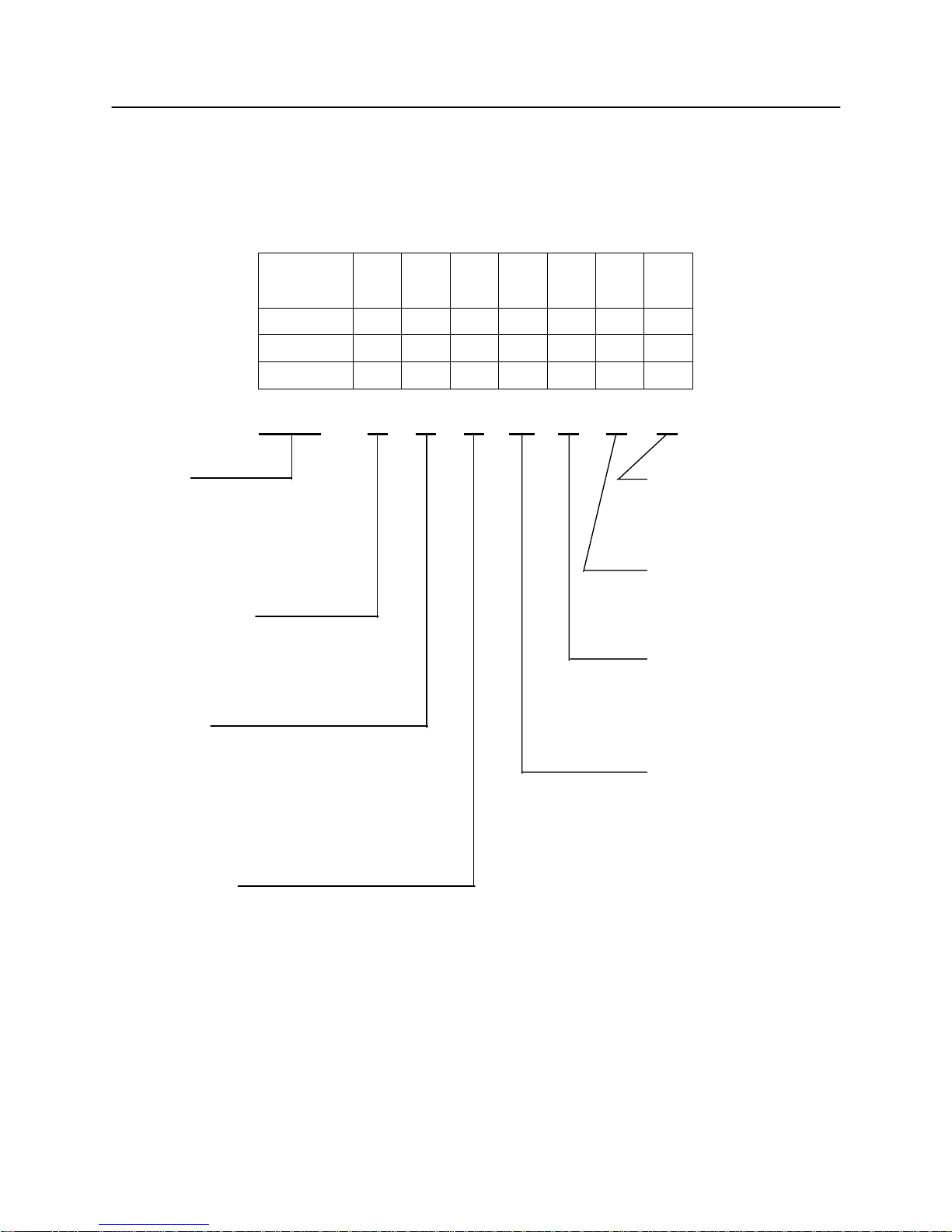
2. TYPE CLASSIFICATIONS
Printer types are classified according to the system shown below.
CBM-710
23
28
40
O
R
X
J F 100
115
230
G
C
B
N
V
–
CBM-720
↑ ↑ ↑ ↑ ↑ ↑
–
CBM-730
↑ ↑ ↑ ↑ ↑ ↑
–
CBM-750
↑ ↑ ↑ ↑ ↑ ↑
–
CBM-710 – 23 R J 100 G – B – V
The exclusive paper winder mechanism (Model AW-2) is available separately. This mechanism can be mounted on
any of the printer types, except CBM-710, 720.
Model
CBM-710
CBM-720
CBM-730
CBM-750
Column capacity
23: 23 columns
28: 28 columns
40: 40 columns
Interface
P : Parallel type P
R : Serial type R
RS-232C
20mA Current loop
X : RS422A
Character set
J : Japanese
F : International
Validation Function
V : With Validation
No symbol : Without Validation
Memory Back-up
B : With Back-up
N : Without Back-up
Mode
G : Graphic
C : Character
I : Character (Type II)
Power Source
100 : AC 100V
115 : AC 115V
230 : AC 230V

CBM-710/720/730/750 User’s Manual
3
CITIZEN
3. SPECIFICATIONS
3.1 General Specifications
Item CBM-710, 730 CBM-720, 750
1 Print Method Bidirectional serial dot impact method
2 Character composition
7 × 7 dots (1ncl. half-dots)
3 Character number per line
23 columns: 230 dot/line
28 columns: 280 dot/line
40 columns: 360 dot/line
4 Print speed
23 columns: approx.4.0 line/sec.
28 columns: approx. 3.5 line/sec.
40 columns: approx. 3.0 line/sec.
5 Character size
23 columns: 1.8(W) × 2.4 (H) mm
28 columns: 1.5(W) × 2.4 (H) mm
40 columns: 1.36(W) × 2.4 (H) mm
6 Line pitch
C: Character Type: 4.23 mm (1/6 inch)
G: Graphic Type: 2.82 mm (1/9 inch)
7 Paper size
Friction Type: 76.0 ~ 0.5 mm (W) ×80 mm (Dia.)
3.0 inch (W) × 3.0 inch (Dia.)
Pin Wheel Type: 76 ~ 89 mm (W)
3 ~ 3.5 inch (W)
8 Interface
P: Parallel interface (8 Bit)
R: Serial interface (RS232C, 20 mA current loop)
X: Serial interface (RS422A)*
2
9 Input buffer 7K bytes or 2 line buffer
10 Input buffer back-up
N Type: Without back-up.
B Type: Duration of back-up: More than 100 hours.
(But after 10 minutes operation)
11 Paper end detection
When paper is near the end, the buzzer actuates and print operation is
interrupted, or PE signal is issued.
CBM-710/720/730/750 User’s Manual
4
CITIZEN
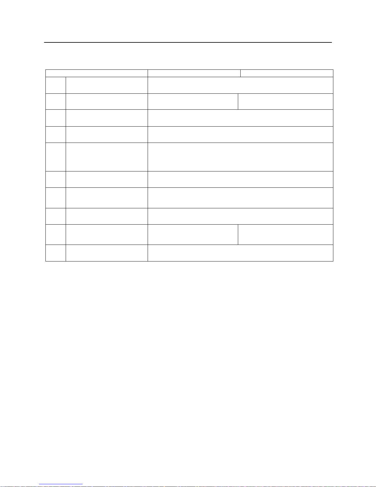
Item CBM-710, 730 CBM-720, 750
12 Validation Print Available only for V-Type (1 line print)
13 Auto cutter Without cutter With cutter Partial cut/Full cut*3
14 Cassette ribbon Two color (Black and Red) print IR-61R/B*4
15 Paper winder Model AW-2 available as option
16 Power voltage*5
100V ± 10%, 50/60 Hz (For Japan)
115V ± 10%, 60 Hz (For United States)
230V ± 10%, 50/60Hz (For Europe)
17 Power consump. Approx. 30W
18 Operation temp. & humidity
5° to 35°C / 41° to 95°F
10% to 85% RH
19 Storage temp. -20° to 70°C
20 Net weight
Approx. 3.1 kg (710)
Approx. 3.3 kg (730)
Approx. 3.3 kg (720)
Approx. 3.6 kg (750)
21 External dimensions Refer to Section 14.
Notes: * l Paper weight of 45 kg refers to 1,000 sheets of 788 × 1,091 mm.
*2 RS-422A interface specifications are not included in this manual
1. With the RS422A type interface, only a one line input buffer can be selected.
2. However, when the input buffer is set for two lines, back-up of graphic data is not possible.
*3 Partial cut is three connecting points remaining. Full cut is one connecting point remaining.
*4 Single color print ribbon is available as option.
Black print: IR-61B
Purple print: IR-61P
V Type: Use only single color print ribbon.
*5 Power voltage setting is performed at the factory.
CBM-710/720/730/750 User’s Manual
5
CITIZEN
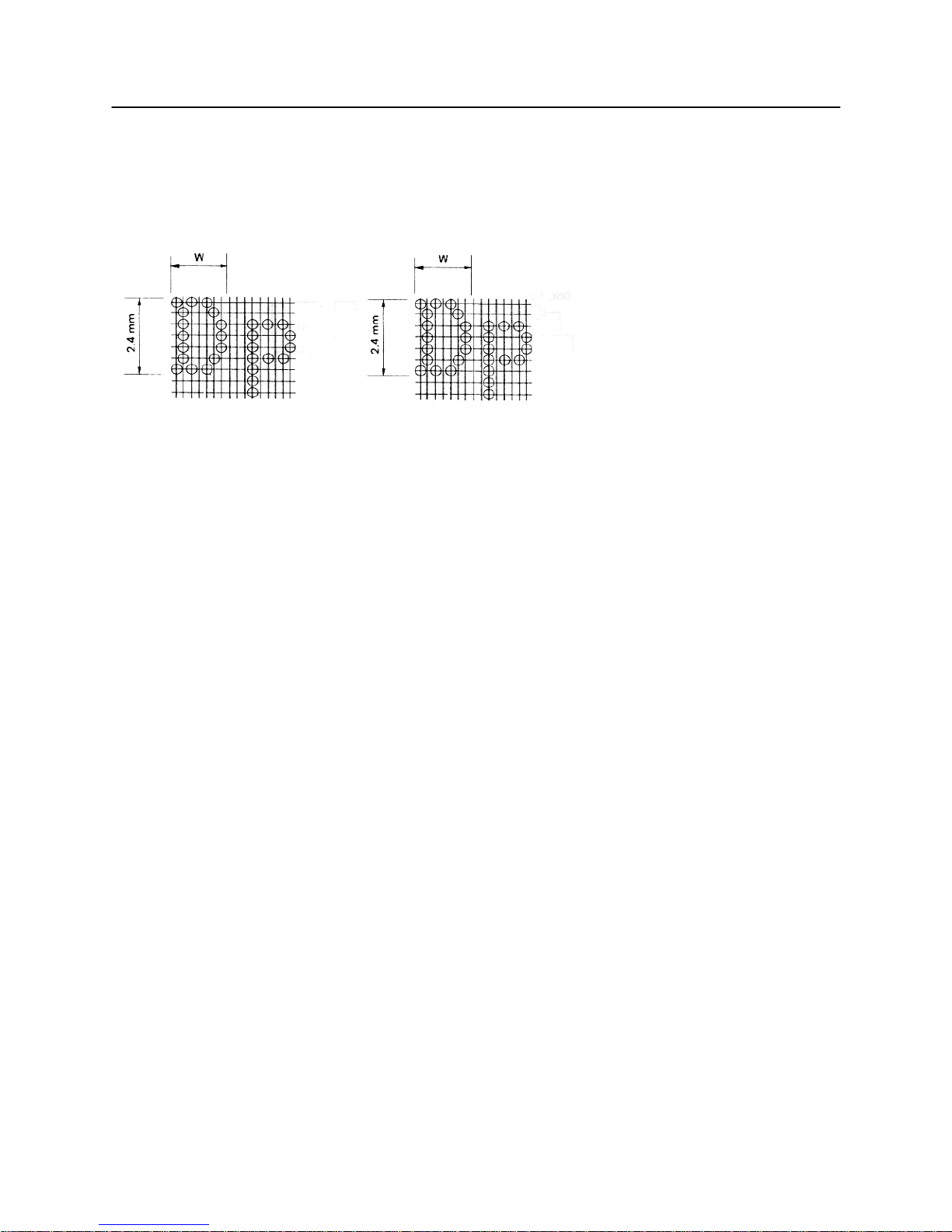
3.2 Print Format
(1) Character Font 7 × 7 dot.
3.3 Paper Specifications
(1) Form Friction specification :
Roll paper
76 - 0.5 mm (Width) × 80 mm (Outer dia.)
Pin wheel specification:
Fan fold paper
Width 76 mm (3 inches) ~ 89mm (3.5 inches)
(2) Type High quality paper with smooth surface
(3) Recommended Paper (Single paper) 45 - 55 kg/1000 sheets/1091 × 788 mm
(Copy) Non-carbon paper
Friction specification:
Original 1 + Copy 1, Each 34 kg paper
Total thickness: 0.13 mm or less
Pin wheel specification:
Original 1 + Copy 2
Use only single color print ribbon
Total thickness: 0.2 mm or less
23 columns: W = Approx. 1.8 mm
28 columns: W = Approx. 1.5 mm
7×7 dots
(
Incl. half-dots)
40 columns: W = Approx. 1.36 mm
7×7 dots (Incl. half-dots)
CBM-710/720/730/750 User’s Manual
6
CITIZEN
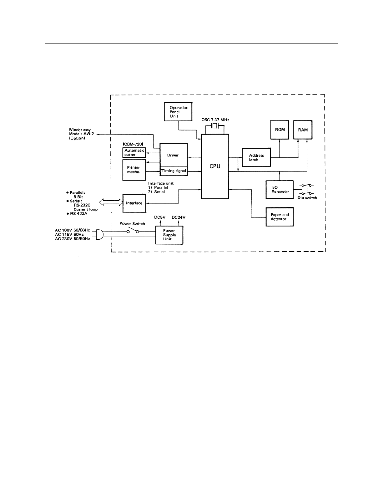
4. BLOCK DIAGRAM
CBM-710/720/730/750 User’s Manual
7
CITIZEN
5. EXTERNAL APPEARANCE AND PARTS DESCRIPTIONS
5.1 CBM-710 External Appearance
Fig. 1 Front View
Fig. 2 Rear View

CBM-710/720/730/750 User’s Manual
8
CITIZEN
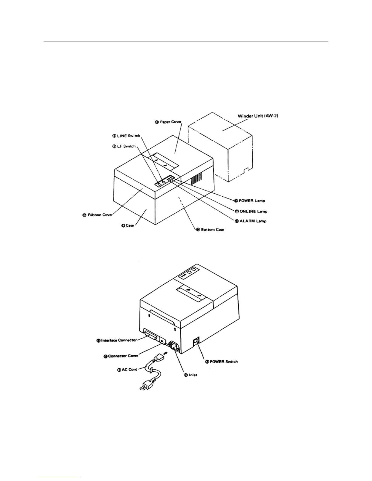
5.2 CBM-720 External Appearance
Fig. 3 Front View
Fig. 4 Rear View
CBM-710/720/730/750 User’s Manual
9
CITIZEN
5.3 CBM-730 External Appearance
Fig. 5 Front View
Fig. 6 Rear View
CBM-710/720/730/750 User’s Manual
10
CITIZEN
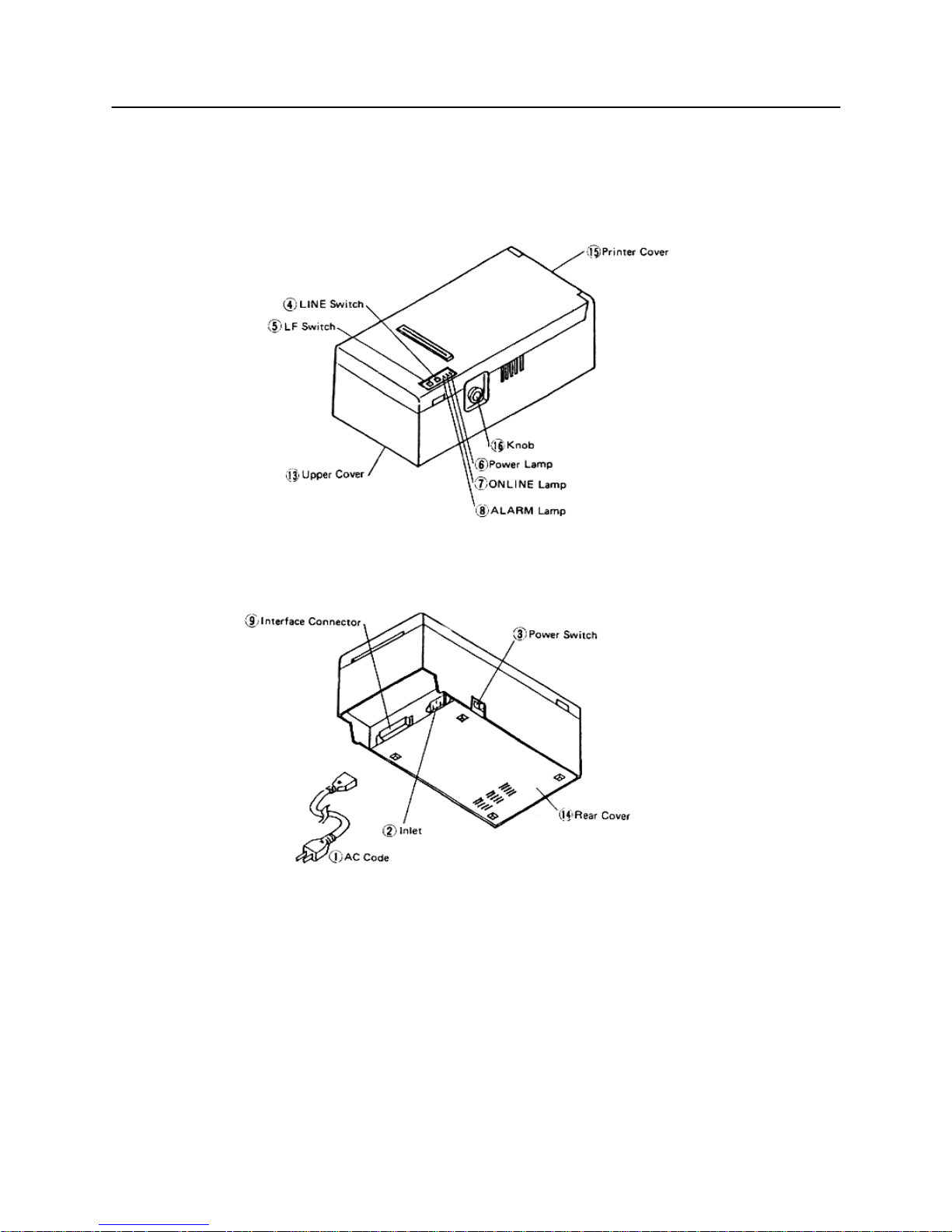
5.4 CBM-750 External Appearance
Fig. 7 Front View
Fig. 9 Rear View

CBM-710/720/730/750 User’s Manual
11
CITIZEN
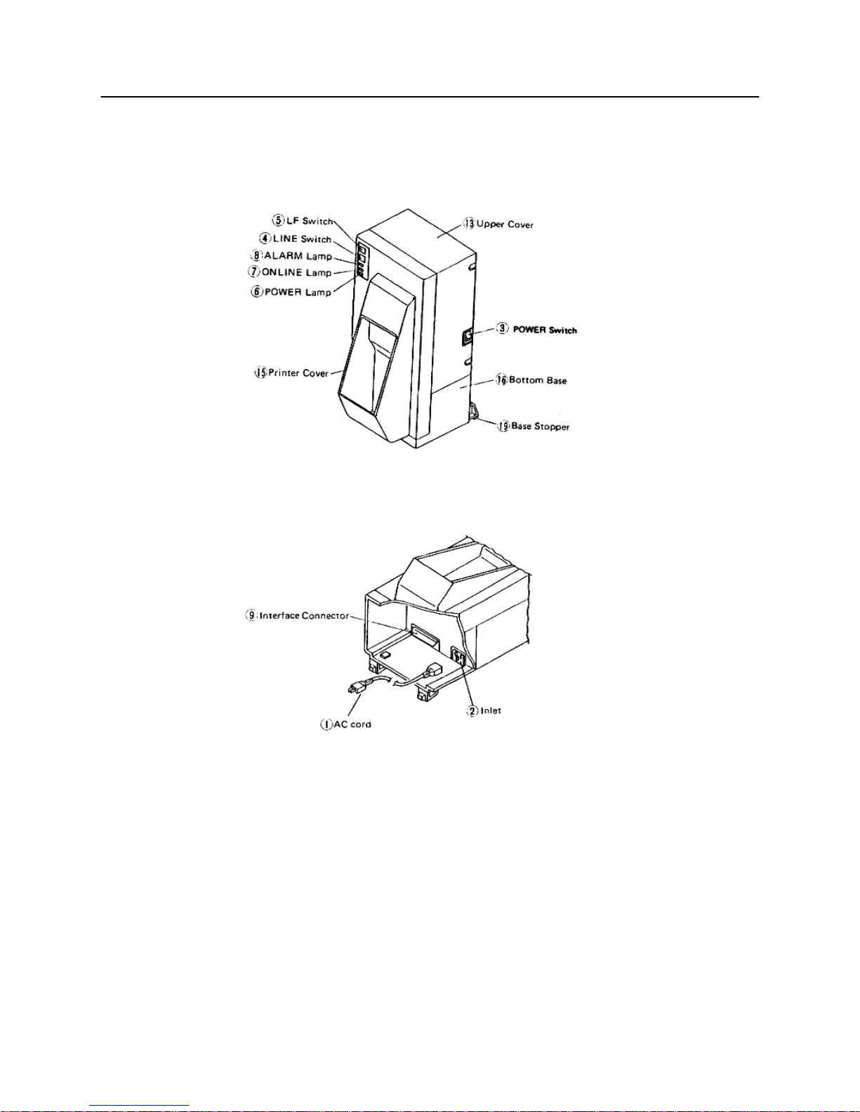
5. 5 Part Descriptions
(1) Power Cord Attach the connector end to the printer inlet, and insert the plug end into an electric outlet.
(2) Inlet This is the electric power inlet. Attach the connector end of the power cord here.
(3 ) Power Switch Power is supplied to the printer by turning this switch on.
(4) Line Switch When this switch is pressed, the printer enters select (on line) status. When pressed again,
the printer enters deselect (off line) status. This switch is also used when clearing an alarm
condition.
(5) LF Switch Paper feeding is performed when this switch is pressed (in deselect status only). This is
used when inserting the paper and for spacing up etc.
(6) Power Lamp This lights up when the power switch is "on" and goes out when turned "off".
(7) On Line Lamp This lights up when the printer is in select (on line) status, and goes out when in deselect
(off line) status. Printing operation is performed only when this lamp is on.
(8) Alarm Lamp This lights up when printer operation is abnormal. When in an alarm condition, printing
and line feed operations are not performed.
(9) Interface Connector Connects through a cable to a computer etc. Please be certain that power to both
the printer and the computer are turned off when connection is made.
(l0) Connector Cover Covers the connector which is used for the paper winder mechanism (AW-2).
(l1) Paper Cover Opens when replacing the paper roll.
(l2) Ribbon Cover Opens when replacing the ribbon.
(l3) Top Case
(l4) Bottom Plate
(l5) Printer Cover
(l6) Paper-Feed Knob
(l7) Bottom Base
(l8) Base Stoppers
CBM-710/720/730/750 User’s Manual
12
CITIZEN
6. OPERATION
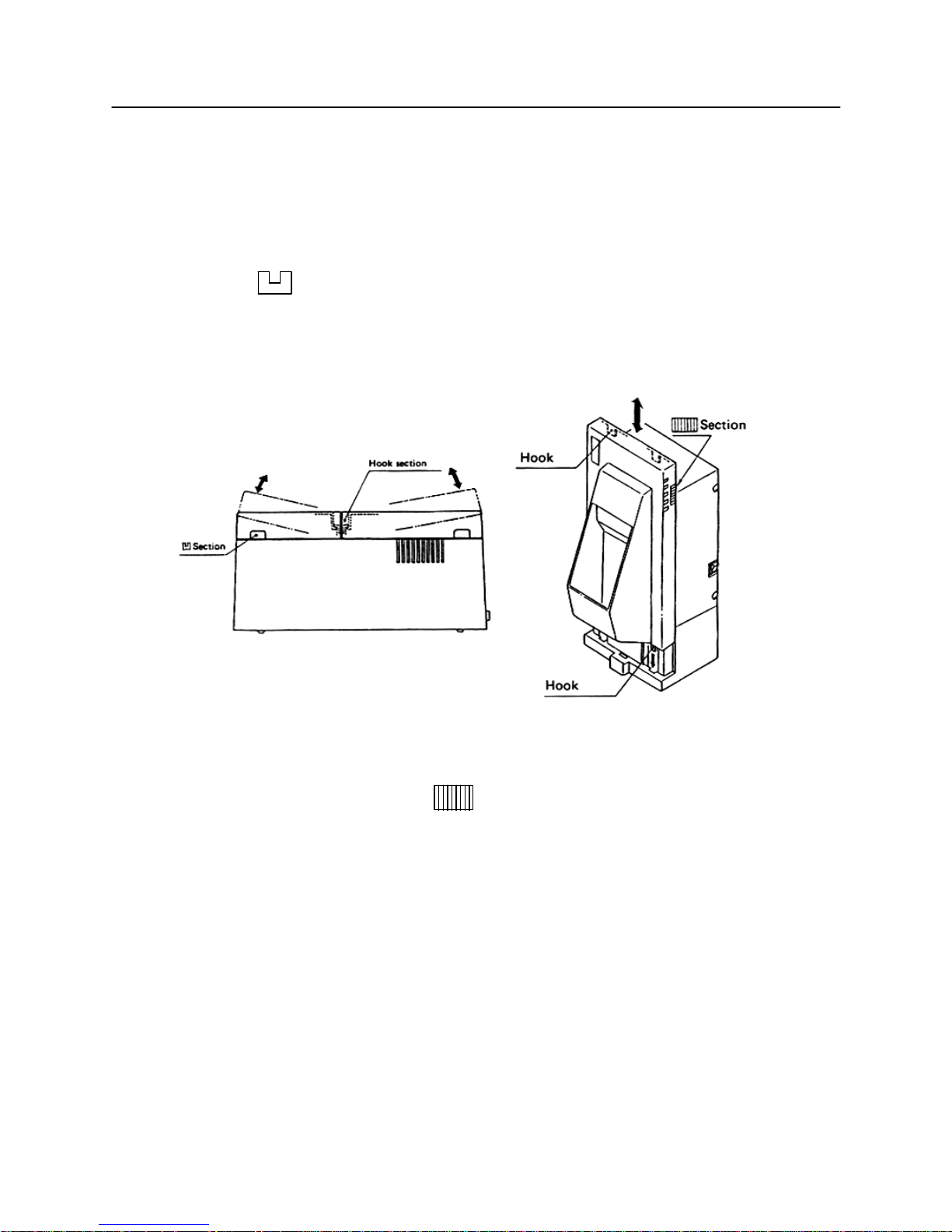
6. 1 Setting and Removing the Paper and Ribbon Covers
1) To open, grasp the sections of the cover with both hands and lift upward.
2) In order to replace the cover, engage the hook section in the middle and press downward in the direction of the
arrow.
Fig. 9 Fig. 10
3) To open the CBM-750's printer cover, grasp the (lines-engraved) section with both hands and lift upward.
4) For replacing the cover of the CBM-750, set 4 pieces of rear hooks into each square hole of the main unit, as
shown in figure 10.
CBM-710/720/730/750 User’s Manual
13
CITIZEN
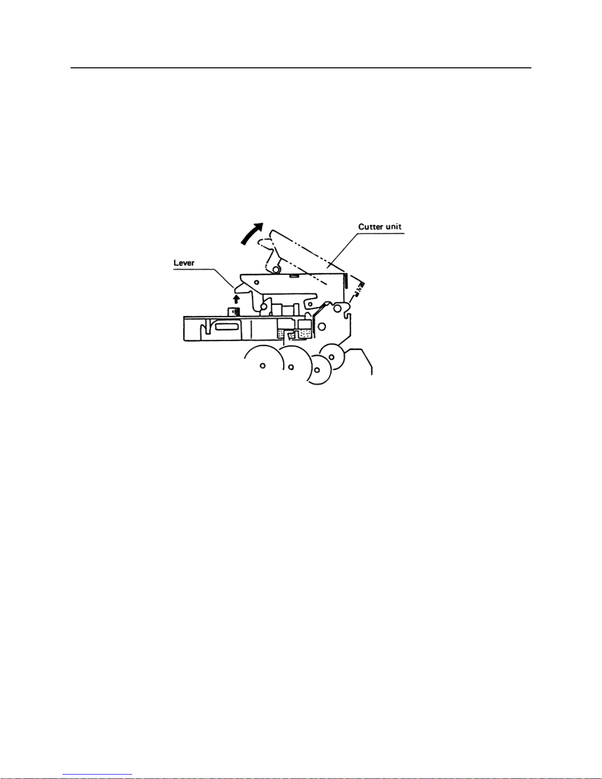
6.2 Opening and Closing the Cutter Unit (CBM-720. CBM-750)
1) To open the unit, grasp two levers and lift upward.
2) When closing the unit, press downward until it completely locks into place.
Fig. 11
CBM-710/720/730/750 User’s Manual
14
CITIZEN
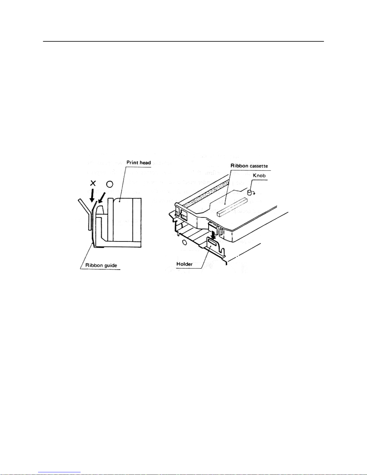
6.3 Installing the Cassette Ribbon
1) First remove the ribbon cover (CBM-710, CBM-730). In the case of the CBM-720, 750 remove both the ribbon
and paper covers and then open the cutter unit. (Refer to figures 9, 10 &11.)
2) While inserting the ribbon into the space between the print head and the ribbon guide, press the cassette into the
holder unit until it clicks into place. (Refer to figure 12 & 13.)
3) Turn the ribbon cassette knob in the direction of the arrow to take up slack in the ribbon.
Fig. 12
Fig. 13
CBM-710/720/730/750 User’s Manual
15
CITIZEN
6.4 Installing and Changing the Paper
(1) Installing the Paper
1) Remove the paper cover.
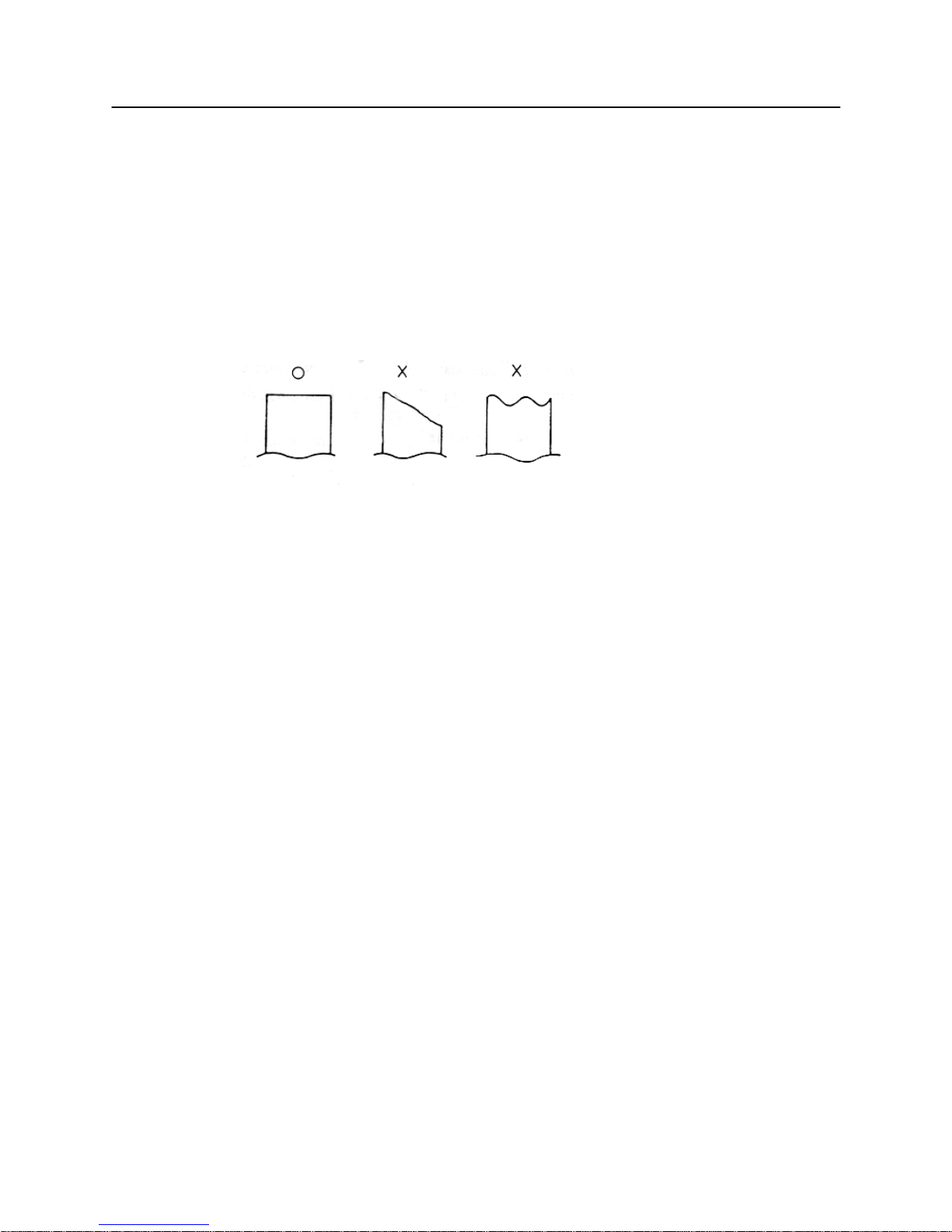
2) Cut the end of the paper off at a right angle as shown in figure 14.
Fig. 14
3) Put the end of the paper into the paper entrance of the printer. (Refer to figure 17.)
4) After turning the power switch on and confirming that the printer is in deselect (off line) status, press the LF
switch to feed the paper into the printer.
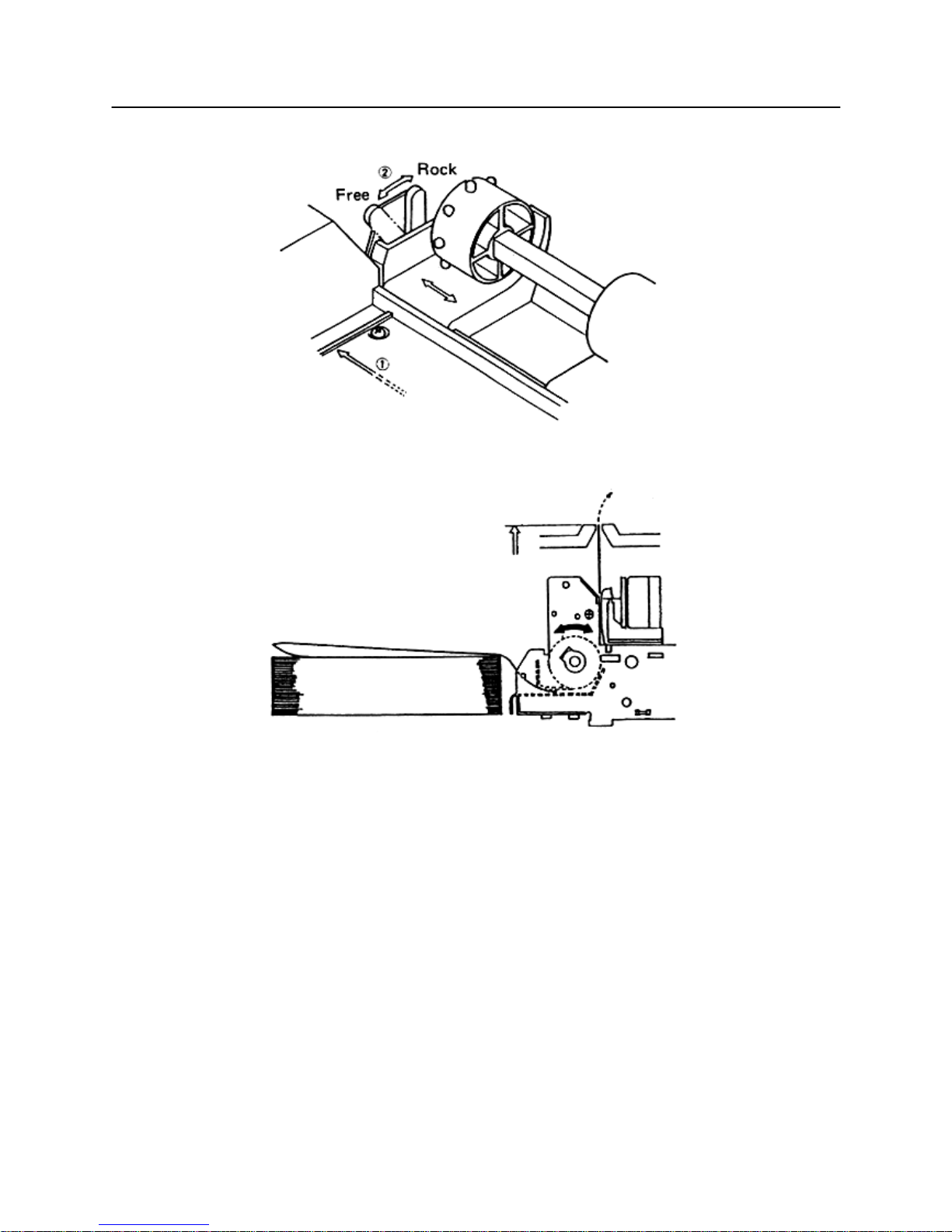
5) In the case of the CBM-730, set the imprint face of the paper downward and put it into the paper entrance (If
using 3.0" width paper, place the paper between 2 bars).
If necessary to adjust the sprocket-wheels' position, free them by the lever and slide to the appropriate position,
and lock it back. (Refer to figure 15.)
CBM-710/720/730/750 User’s Manual
16
CITIZEN
Fig. 15
Fig. 16
Hook some of the paper's perforations on the sprockets and forward the paper into the printer by turning the paperfeed knob until the paper's tip protrudes 5 - 6 cm from the printer.
In the case of the CBM-710, use the LF switch to feed the paper.
CBM-710/720/730/750 User’s Manual
17
CITIZEN
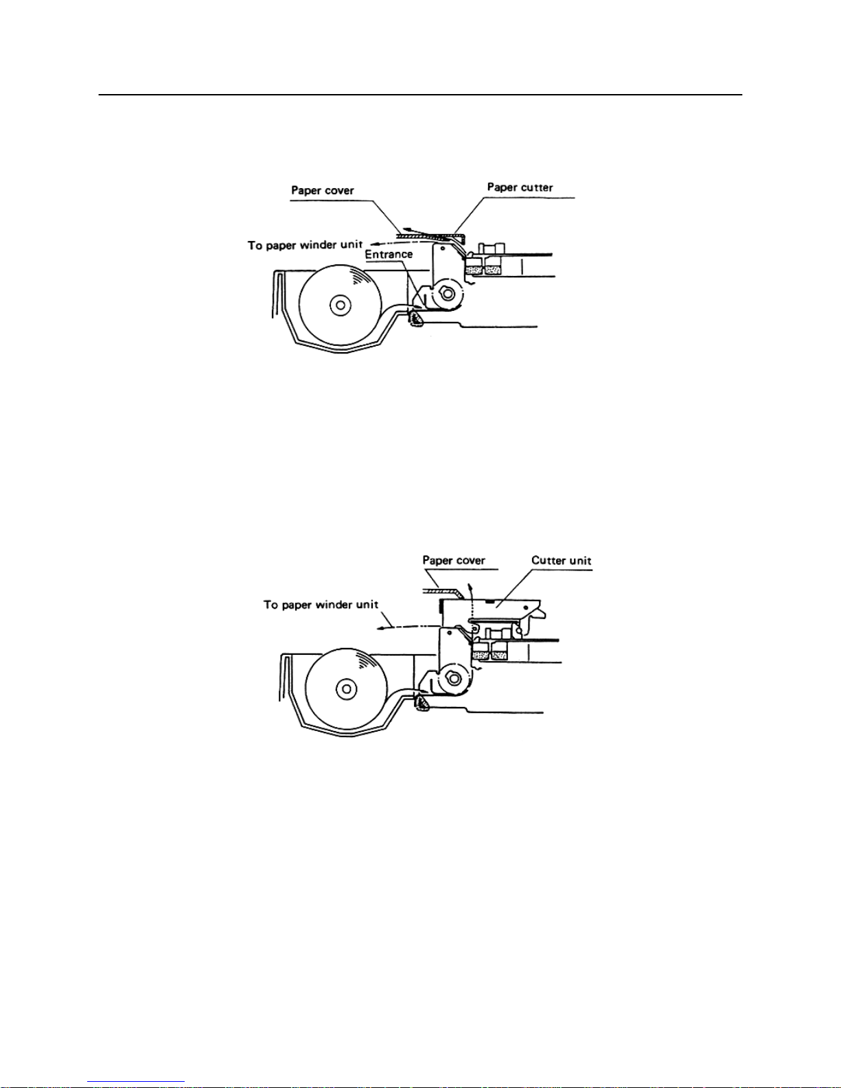
6) When using the paper winder mechanism (AW-2), feed the paper toward the rear of the printer from the
inside of the paper cover, and secure it to the take-up spool.
Fig. 17
7) In the case, of the CBM-720, attach the printer cover, press the LFswitch, and confirm that the paper comes
out of the paper exit. When the paper winder mechanism is being used, lift the cutter unit to pass the paper
through as shown in figure 18, Then feed the paper towards the rear of the printer from the inside of the paper
cover, and secure it to the take-up spool.
Fig. 18

CBM-710/720/730/750 User’s Manual
18
CITIZEN
(2) Changing the Paper
1) Cut off the remaining paper near the entrance to the printer.
2) If the alarm lamp is on, turn it off by pressing the line switch.
3) Feed the paper out of the printer by pressing the LF switch or pull it out from the paper exit.
4) Install a new paper roll. (Refer to section 6.4 (1) Installing the paper.)
5) When the line switch is pressed again, the printer enters select (on line) status and printing may be resumed
once again.
6.5 Self Print Function
Your printer has a built in self print function for the purpose of checking print operation without the need for any
other external device.
Procedures for Actuating the Self Print Function
[1] Be sure that a paper roll is properly loaded.
[2] Confirm that the inked ribbon is properly installed and turn the power switch off.
[3] Turn the power switch ON while pressing the LF switch, and release the LF switch after the self print
operation has begun.
In the above operation, the se print unction will stop automatically when completed.
However, the self print function will not operate without paper when the printer is set for internal process of the
paper end detection function.
6.6 Paper End Detector
Your printer provides a paper end detection function which is able to detect when the paper is near the end. In
addition. two different responses to this situation may be selected.
[1] Issue the PE signal to an external unit(s).
[2] Perform internal processing, whereby the buzzer is sounded and the print operation of your printer is
interrupted.
CBM-710/720/730/750 User’s Manual
19
CITIZEN
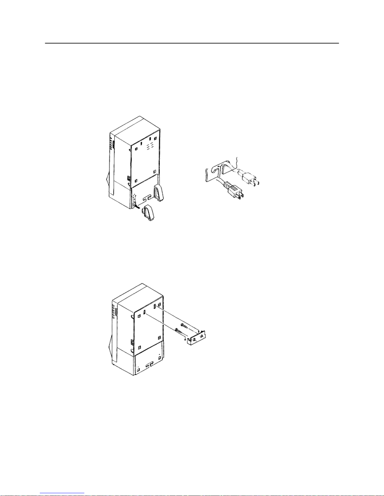
6.7 Installation of the CBM-750
1) Table-top use
Put the AC cord into the "T" hole of the bottom base. Install the base stoppers, as shown in the figure 19.
Fig. 19
2) Wall-mounting use
Fix the hanger with 2 screws to the wall and hook the unit as shown in the figure 20.
Fig. 20
 Loading...