

CBM 250, 400, 420, 300, 280 Quick Start Manual
...
STEP
1:
1 2
STEP
2:
A
1
2
A
OR
1 2 3 1 2 3 1
Back-UPS (VA):
Back-UPS PRO (VA):
250, 280, 300, 400, 420, 450, 500, 600, 650
650, 1000, 1100, 1400
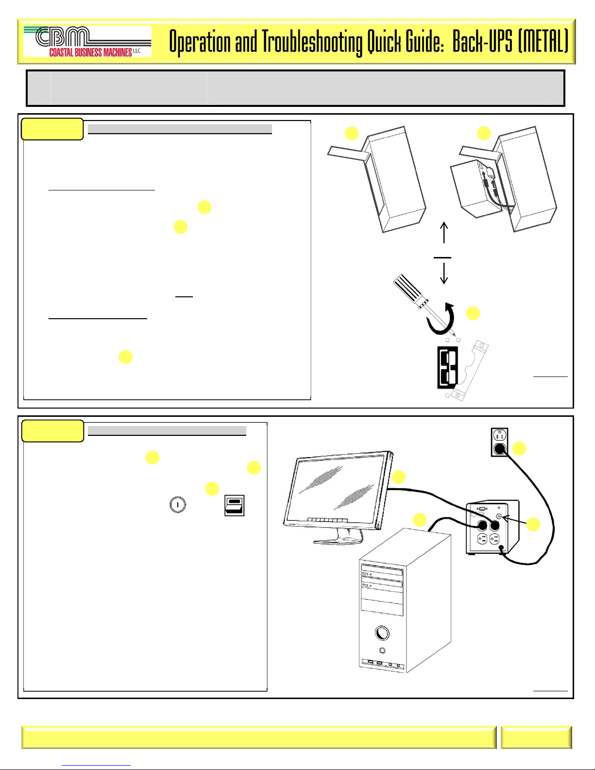
Connect the UPS’s Internal batteries (Figure 1):
NOTE: Battery Disconnect/Connector may vary or be
omitted on some models. Figure 1 illustrates some of the
variations in connectors. Please follow the illustration
which best resembles your UPS.
Procedure for Figure 1: (1, 2)
1.1 Remove the two screws holding the battery door.
1.2 Lay the UPS on its side and open the door
1.3 Gently pull the battery out.
1.4 Connect the two wires to the battery
NOTE: Make sure to observe the polarity (Red-to-Red, Black-to-Black)
NOTE: Small sparks at the battery connections are normal.
1.5 Insert the battery in the UPS. Carefully avoid pinching the wires.
1.6 Close the battery compartment door and replace the screws.
OR
Procedure for Figure 1: (A)
1.1 Locate the ‘Battery Disconnect’ on the rear panel of the UPS. It is typically
a Yellow connector.
1.2 If the Battery Disconnect has a metal cover, remove the fastening screws
and move the cover
1.3 Press the yellow connector into the Battery Jack. A snap will be felt as the
connector partially engages the jack. A second snap will be felt as the
connector securely seats in the Battery Jack.
Figure 1
Connect wiring & charge UPS (Figure 2):
NOTE: Ensure equipment is turned off.
2.1 Connect equipment to UPS
2.2 Connect UPS Power Cord to a suitable power receptacle
2.3 Reset the UPS Circuit Breaker by pushing-in the button
(Circuit breakers may differ on some models)
2.4 Power-up the UPS by pressing the button or
Switch.
2.5 Wait for the Self-Test to complete, then Power-up equipment.
2.6 Allow UPS to charge batteries for 24 hours prior to operating
on battery or performing additional Self-Test or Calibration
tests.
C B M _ O T Q G _ B U 3 _ 2 0 1 1 0 8 0 9 V 0 2
Figure 2
Page 1
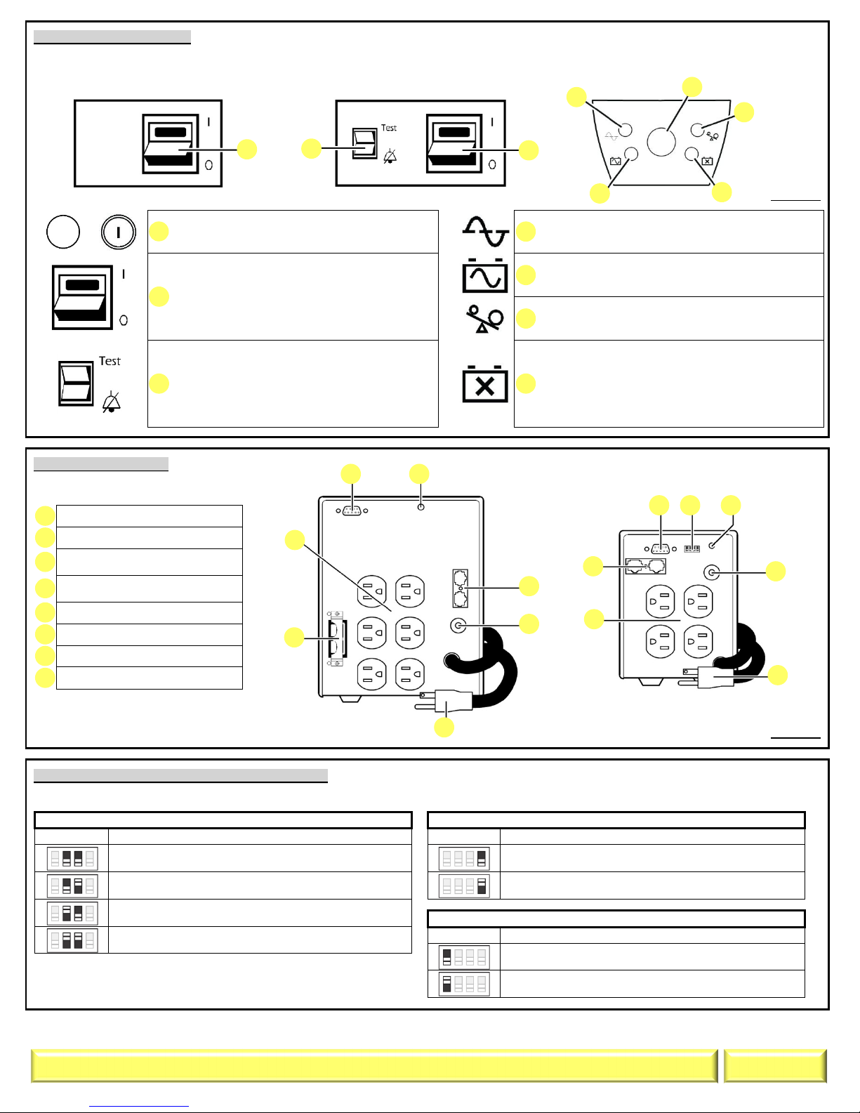
UPS Front Panel (Figure 3):
to turn UPS
UTILITY TRANSFER VOLTAGE
Position:
Result:
AUDIO SETTING
Position:
Result:
SHUTDOWN SETTINGS
Position:
Result:
1 4
2
5 6
3 7
1
2
3 4
5
6 7 8
2 2
3 1 4 5 6 7 1 5 4 3 2 7 6 4 1 2 3 6 5 8
NOTE: Symbols & functions may differ on some UPS models.
Figure 4 illustrates some of the variations in displays.
Please use the illustration which best resembles your UPS.
POWER ‘ON/OFF’ &/OR TEST BUTTON -
Button to turn UPS on or off, or perform a self-test.
POWER ‘ON/OFF’ SWITCH - Switch
on or off. The switch will illuminate when power is
present on the output receptacles.
TEST SWITCH - When operating on Utility
power, the top part of the switch will cause the UPS
to simulate a power outage.
ALARM DISABLE SWITCH - When operating
on battery, the bottom part of the switch will disable
the audible tone.
Figure 3
ONLINE - UPS is supplying utility power to the
connected equipment. If not lit, the UPS is not turned
ON, or is supplying battery power.
ON BATTERY - UPS is supplying battery backup
power to the connected equipment. UPS will beep four
times every 30 seconds.
OVERLOAD - The power demand from the load has
exceeded the capacity of the UPS. A sustained alarm
tone is also emitted.
REPLACE BATTERY - UPS fails a self-test, or
battery is bad. UPS makes short beeps for a minute.
BATTERY DISCONNECTED - Flashes to indicate
the battery is disconnected. UPS will beep every two
seconds.
UPS Outlets (Figure 4):
NOTE: Panel Layout may differ
depending on model.
DB9 Serial Port
Site wiring fault Indicator
Modem/Phone/FAX/Network
surge protection
Circuit breaker/Overload
protection
UPS input
Outlets
Battery Disconnect
Option Switches
Option Switch configuration (Figure 4, reference #8):
NOTE: Option switch may not be included on some models. ‘Shutdown Settings’ function is only available on 500 & 650 VA models.
(NORMAL SETTING) 103V AC
(NORMAL SETTING) AUDIO is enabled.
Figure 4
98V AC
93V AC
88V AC
C B M _ O T Q G _ B U 3 _ 2 0 1 1 0 8 0 9 V 0 2
AUDIO is disabled.
(NORMAL SETTING) 2 min. prior to shutdown, UPS will
sound a tone & activate low battery signal on COM port.
Same actions as “NORMAL SETTING”, but delay is
increased to 5 minutes instead of 2 minutes.
Page 2
 Loading...