

CBI QAT-R-DM-M, QAT-R-DM-H Installation And Programming Manual
QATRDM | Rev A
QAT-R-DM – (M or H) ELECTRONIC TIME SWITCH
L N
L
Time
Switch
L N
L N
(Load)
Appliance
Neutral
Bar
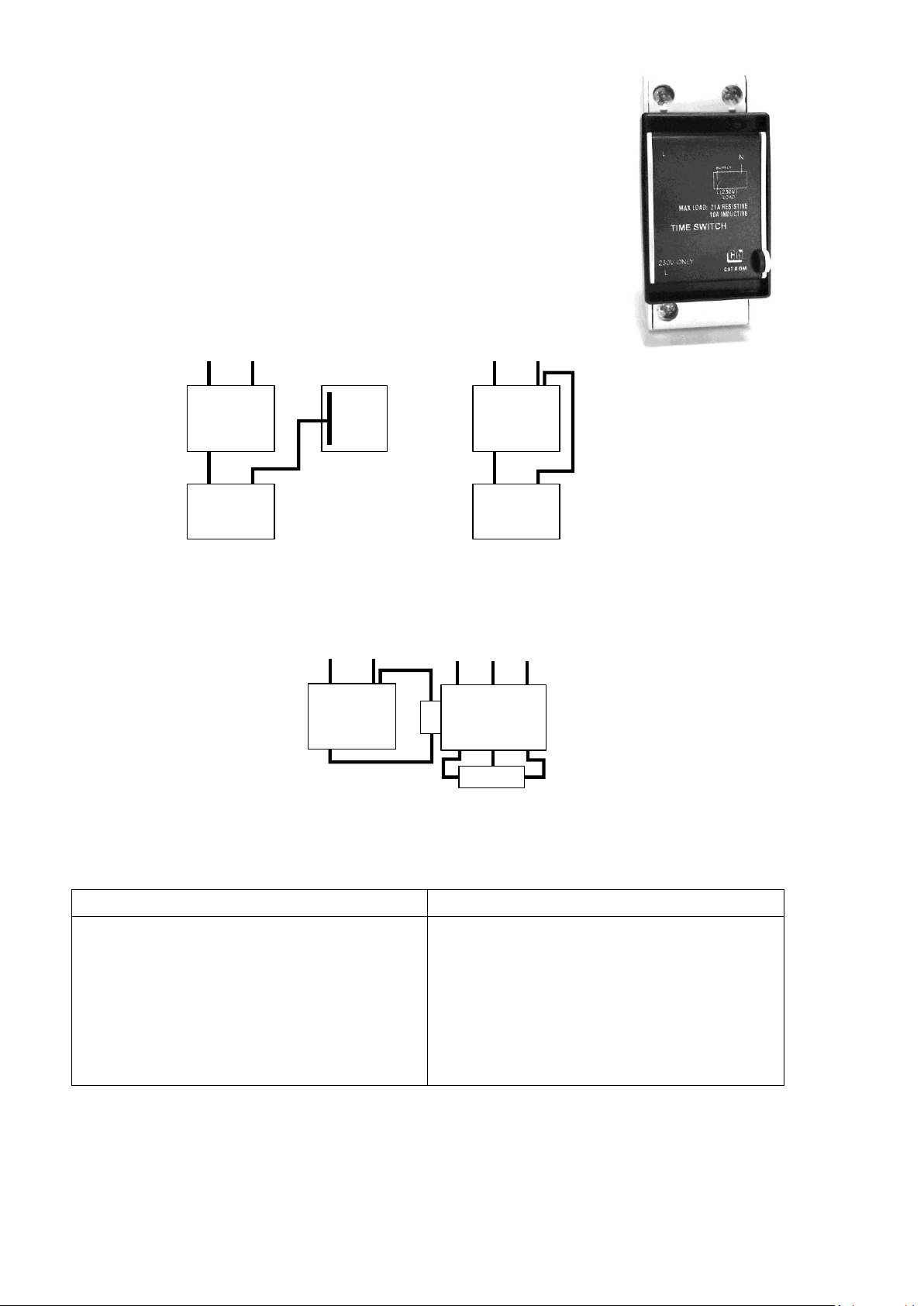
Figure 1: DB wiring
L N
L
Time
Switch
L N
L N
(Load)
Appliance
Figure 2: Stand alone wiring
L N
L
Time
Switch
L N
Coil
Contactor
L1 L2 L3
T1 T2 T3
Supply
Load
PRODUCT SPECIFICATION
Supply Voltage
Resistive load (Geysers, under floor heating, lights)
Inductive load (Pool pump, air conditioners)
Degree of Ingress Protection
Endurance
Operating Temperature
Reserve full charging time
Single segment period
Maximum period for all segments
Clock accuracy
230 VRMS 50 Hz
Maximum 21 A
Maximum 10 A
IP41(Not waterproofed)
25 000 (minimum) Operations at maximum load
-20 °C to +55 °C
12 hours
30 minutes
48 x 30 minute segments
2 to 4 minutes per month
Installation and programming guidance
GENERAL: The programmable time switch can be used to automatically control pool pumps,
lights, geysers. etc.
Important Notes:
1. The time switch has a backup power feature which requires 12 hours to fully charge.
(A fully charged time switch will retain its program and time for up to 24 hours, in the
case of a power failure).
2. Pushing any button during a power failure will reduce the backup power period.
3. CBI advises that the time switch be installed by a suitably qualified person.
ISOLATE POWER BEFORE INSTALLATION
● Install the time switch on either mini rail or din rail with the clock screen up-right.
● Wire the time switch according to Figure 1 or Figure 2.
WARNING: Do not connect more than 21A resistive or 10A inductive loads to the time switch.
For loads larger than 21A resistive or 10A inductive, connect a suitable contactor to the time switch output.
Refer to Figure 3 for connections.
Figure 3: Wiring a contactor for loads greater than
21A resistive or 10A inductive.
TECHNICAL DATA
Page 1 of 2
BOM:3990A640
QATRDM | Rev A
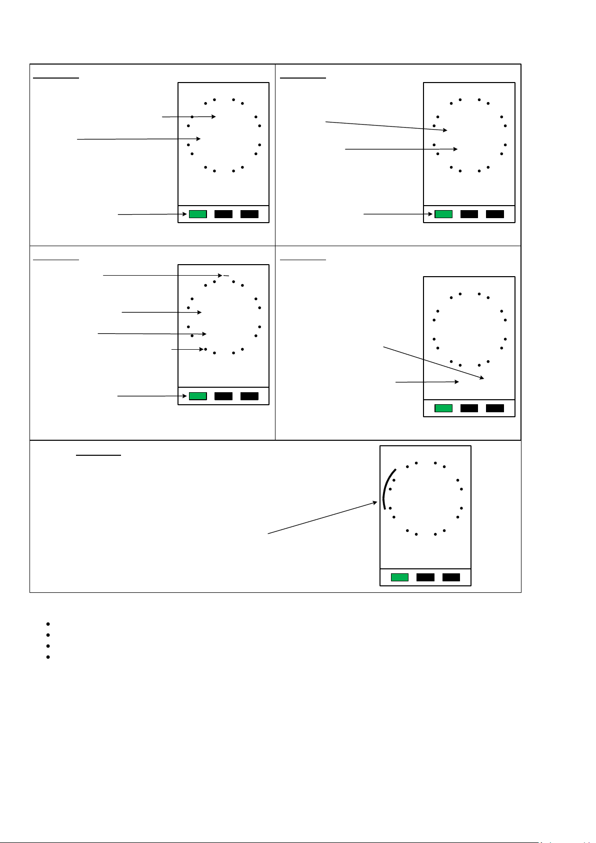
PROGRAMMING
24
3
6
9
12
15
18
21
21:00
FUNCTION
PROGRAM
ON OFF
EXAMPLE: FOR AN APPLIANCE TO BE ON BETWEEN 17:00 AND 21:00
PRESS – OFF button until the program time indicate 17:00
PRESS – ON button repeatedly until the program time indicates 21:00
PRESS – FUNCTION button once to move to screen 4
Segment display of the programmed time duration
SCREEN 3: PROGRAM TIMER ON / OFF
Flashing segment time
PRESS – OFF button to get to start program time (load – OFF)
PRESS – ON button repeatedly to set the program “on”
duration (Load – ON)
Green function button
Screen indicator
SCREEN 4: BYPASS ON OR OFF
PRESS “BYPASS-ON” button
to switch the load on permanently.
The BYPASS ON flashes on the
display.
PRESS – Green FUNCTION button to move to screen 1
24
3
6
9
12
15
18
21
00:00
FUNCTION
PROGRAM
ON OFF
24
3
6
9
12
15
18
21
15:00
FUNCTION
BYPASSONBYPASS
OFF
ON OFF
Flashing segment
Hourly increments on the clock face
The timer program is bypassed during this screen
PRESS “BYPASS-OFF” button
the timer operates according
to the set program.
The BYPASS-OFF flashes on the
display.
SCREEN 1: ACTUAL TIME INDICATOR
OFF indicator for the timer switch
PRESS – Green FUNCTION button once to move to screen 2
Green function button
Actual time
24
3
6
9
12
15
18
21
00:00
FUNCTION
OFF
SCREEN 2: SET ACTUAL TIME
Actual time
Screen indicator
Green function button
PRESS – HOUR and MIN button to set actual time
PRESS – Green FUNCTION button once to move to screen 3
24
3
6
9
12
15
18
21
14:55
FUNCTION HOUR MIN
CLOCK
SET
When the timer is powered up screen 1 (main screen) will appear.
Additional Notes:
The timer goes through a self-test at start up, wait for the timer to finish before entering any data.
The program cycle repeats every day.
If no button is pressed, after 1 minute the timer will revert to screen 1.
If desired, more than one Load-ON period can be programmed, e.g. Appliance ON between
04:00 - 07:00 and 13:00 - 16:00.
Page 2 of 2
BOM: 3990A640
 Loading...